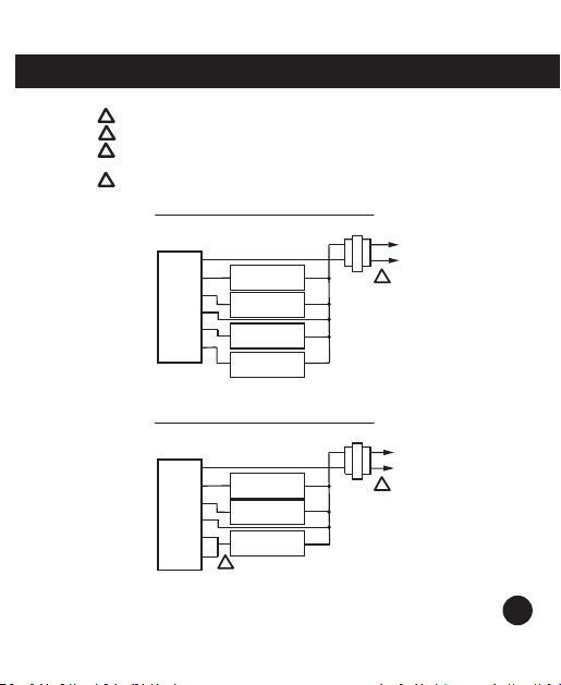
Islandaire 6041206 User manual

NON-PROGRAMMABLE
WIRELESS THERMOSTAT
6041206
Installaon and Operaon Manual
6140429 Rev. 08/24/20


Descripon
Gas or Oil Heat Yes
Electric Furnace Yes
Heat Pump (No Aux. or Emergency Heat) Yes
Heat Pump (With Electric Aux.) Yes
Heat Pump (With Gas Aux.) No
Mul-Stage Systems No
Heat Only Systems - Floor or Wall Furnace Yes
Cool Only Systems Yes
High and Low Fan Speed Yes
Millivolt No
Emergency Heat No
Convenonal Single-Stage Furnace Yes
Geothermal Yes
Table of Contents page
Installaon Tips 2-3
Thermostat Quick Reference 4
Wiring 5-6
Wiring Diagrams 7-8
Technician Setup 9-10
Swing Seng 11
Specicaons 12
Thermostat Applicaon Guide
Baery Power
Hardwire (Common Wire)
Hardwire (Common Wire) with
Baery Backup
A trained, experienced technician
must install this product.
Carefully read these instrucons. You
could damage this product or cause
a hazardous condion if you fail to
follow these instrucons.
Power Type
1
Installaon and Operaon Manual

Wall Locaons
The thermostat should be installed approximately 4 to 5 feet above the oor. Select an area
with average temperature and good air circulaon.
Subbase Installaon
Horizontal Mount
Vertical Mount
1
2
For vercal mount, put one screw on the top
and one screw on the boom.
For horizontal mount, put one screw on the le
and one screw on the right.
Installaon Tip
Pick an installaon locaon that is easy for
the user to access. The temperature of the
locaon should be representave of the
building.
Do not install
thermostat in locaons:
• Close to hot or cold
air ducts
• That are in direct sunlight
• On an outside wall
• In areas that do not
require condioning
• Where there are dead
spots or dras (i.e., in
corners or behind
doors)
• Where there might be
concealed chimneys
or pipes
Installaon Tip
Electrical Hazard
Failure to disconnect the power before
beginning to install this product can cause
electrical shock or equipment damage.
Mercury Noce
All of our products are mercury free.
However, if the product you are replacing
contains mercury, dispose of it properly.
Your local waste management authority can
give you instrucons on recycling and proper
disposal.
2
Installaon Tips

Installaon Manual
Mount Thermostat
Align the 4 tabs on the subbase with corresponding slots on the back of the thermostat,
then push gently unl the thermostat snaps in place.
Baery Installaon
1.5V AAA 1.5V AAA
Baery installaon is oponal if thermostat is
hardwired (RH and C terminal connected to 24V
power).
Important:
High quality alkaline baeries are recommended.
Rechargeable baeries or low quality baeries
do not guarantee a 1-year life span.
Insert 2 AAA
Alkaline baeries
(included). High
quality alkaline
baeries are
recommended.
RH
C
3
Installaon Tips

Geng to know your thermostat
LCD
Fan Switch
System Switch
Setpoint Buons
Indicates the
current room
temperature
Displays the user
selectable setpoint
temperature
System operaon
indicators: On will
display when Cool or
Heat mode is selected
Low Baery indicator:
Replace baeries when
indicator is shown
1
2
3
4
Press the + or - buttons to select the desired room
temperature.
LCD
1
AUTO will turn the fan on only when the heating
or cooling system is on. Select LOW or HIGH for
the fan to run continuously at the selected speed.
Fan Switch
2
3
4
Selects the operation mode on your HVAC system.
Selecting HEAT turns on the heat mode. Selecting
COOL turns on the cool mode. Selecting OFF turns
both heating and cooling o.
System Switch
Setpoint Buons
4
Thermostat Quick Reference

Wiring
This thermostat is shipped from the factory to operate a convenonal heang and cooling
system. This thermostat will also operate a heat pump system. See the “heat pump”
conguraon step on page 10 of this manual to congure the thermostat for heat pump
applicaons.
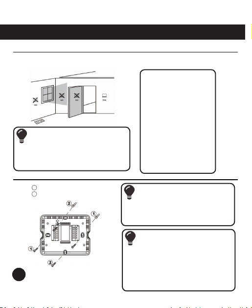
1. If you are replacing a thermostat,
make note of the terminal
connecons on the thermostat that
is being replaced. In some cases
the wiring connecons will not be
color-coded. For example, the red
wire may not be connected to the
R terminal.
2. Loosen the terminal block screws.
Insert wires then reghten terminal
block screws.
Terminal 1 Heat 1 Cool
Convenonal System
1 Heat 1 Cool
Heat Pump System
2 Heat 1 Cool
Heat Pump System
R Transformer power Transformer power Transformer power
CTransformer common Transformer common Transformer common
B/O Energized in heang /
Energized in cooling
Energized in heang /
Energized in cooling
Energized in heang /
Energized in cooling
GL Fan Relay, Low Fan Relay, Low Fan Relay, Low
GH Fan Relay, High Fan Relay, High Fan Relay, High
W Convenonal heat N/A Emergency heat
YEnergized in cooling Energized in heat & cool Energized in heat & cool
Installaon Tip
Do not overghten
terminal block screws,
as this can damage the
terminal block. A damaged
terminal block can keep
the thermostat from ng
on the subbase correctly
or cause system operaon
issues.
Max Torque= 6 in-lbs.
5
Wiring

Wiring Tips
Power Connecons
The thermostat can be either baery
powered, or hard-wired to power by
connecng supply voltage wire (red) and
common wire to the RH and C terminals,
respecvely, on the base.
Installaon Tip
Electrical Hazard
Failure to disconnect the power
before beginning to install this
product can cause electrical shock or
equipment damage.
Wire Specicaons
Use shielded or non-shielded
18-22 gauge thermostat wire.
Warning:
All components of the control
system and the thermostat
installaon must conform to Class
ll circuits per the NEC Code.
Note:
When connecng the 6041206 thermostat to a PTAC, refer to the PTAC
manufacturer instrucons to enable remote thermostat operaon.
6
Wiring

R
Y
W
C
GL
GH
C
R
L1
L2
COMPRESSOR
RELAY
HEAT RELAY
FAN LOW RELAY
FAN HIGH RELAY
1
C
R
L1
L2
COMPRESSOR
RELAY
HEAT RELAY
FAN RELAY
1
2
R
Y
W
C
GL
GH
Typical 1H/1C Convenonal System: 2 Speed Fan
1
2
3
4
Power supply
Jumper (not supplied) to connect GL and GH terminals
The Aux Heat Relay is energized as the second stage of heat.
Typical 1H/1C Convenonal System: 1 Speed Fan
Thermostat changeover valve must be set to b on all
non-Heat Pump Systems.
7
Wiring Diagrams

C
R
L1
L2
COMPRESSOR
RELAY
CHANGEOVER VALVE
FAN LOW RELAY
FAN HIGH RELAY
1
3
C
R
L1
L2
COMPRESSOR
RELAY
CHANGEOVER VALVE
FAN LOW RELAY
FAN HIGH RELAY
1
B
3
EMERGENCY
HEAT RELAY
R
Y
W
C
GL
GH
B
R
Y
W
C
GL
GH
Typical 1H/1C Heat Pump System: 2 Speed Fan
Typical 2H/1C Heat Pump System: 2 Speed Fan
1
2
3
Power supply
Cap off W
Thermostat must be set to B on all Heat Pump Systems
2
Note:
Most PTAC systems support two speed fan operaon. In a single speed
fan PTAC system or convenonal single speed fan system, the GL and GH
wires on the receiver unit should both be ed to the Fan Wire (green).
8
Wiring Diagrams

Fan Operaon Setup
Electric: The thermostat
operaon switch should be
put in the ELEC posion.
This seng allows the
thermostat to operate the
fan during a call for heat.
Most PTAC systems will
require ELEC Fan Operaon
Setup.
Gas: For systems that
control the fan during a
call for heat, put the switch
in the GAS posion.
Technician Setup Menu
1. Set the thermostat system switch to OFF.
2. To enter Tech Setup Menu, press and hold “+”and “-” together for 3 seconds.
3. Use “+” and “-” to select desired seng for each opon.
4. Tap “+” and “-” together to move next opon.
5. To exit Tech Setup Menu, move system switch or wait for 15 seconds.
Select ELEC or GAS
with this switch
9
Technician Setup

Tech Setup Steps LCD Will Show Adjustment Opons Default
Room
Temperature
Calibraon
This feature allows the
installer to change the
calibraon of the room
temperature display.
For example, if the
thermostat reads 70°
and you would like it to
read 72°, then select +2.
You can adjust the
room temperature
display to read up to
4˚ above or below
the factory calibrated
reading.
Pair Transmier and receiver
pair code Press and hold “+” for
3 seconds unl “LE”
is ashed, then release
F or C Select for F for Fahren-
heit temperature read
out. Select C for Celsius
temperature read out.
F for Fahrenheit
C for Celsius
Compressor
Short Cycle
Delay
The compressor short
cycle delay protects the
compressor from short
cycling. This feature
will not allow the
compressor to be turned
on for 5 minutes aer it
was last turned o.
Selecng ON will not
allow the compressor
to be turned on for 5
minutes aer the last
me the compressor
was switched o.
Select OFF to remove
this delay.
Change Over
Value Selec-
on*
Select 0 for a change-
over valve that energizes
in cooling. Select b for
a changeover valve that
energizes in heang.
0 for cooling
changeover valve.
b for heang
changeover valve.
Heat Pump When turned on the
thermostat will operate
a heat pump. Y will be
the rst stage of heat
& cool, W will be the
second stage of heat.
OFF congures the
thermostat for non
heat pump systems.
ON congures the
thermostat for heat
pump systems.
Heang
Temperature
Setpoint
Limit
This feature allows you
to set a maximum heat
setpoint value. The
setpoint temperature
cannot be raised above
this value.
44.0˚ - 90.0˚ F
7.0˚ - 32.0˚ C
Cooling
Temperature
Setpoint
Limit
This feature allows you
to set a maximum cool
setpoint value. The
setpoint temperature
cannot be raised above
this value.
44.0˚ - 90.0˚ F
7.0˚ - 32.0˚ C
* All Islandaire units should always be set to b
10
Technician Setup Menu

1. Set the thermostat system switch to the desired posion (COOL or HEAT).
2. Press and hold “+” and “-” together for 3 seconds.
3. Use “+” and “-” to adjust desired swing seng (the display reads in tenths of a degree.)
4. To exit, move system switch or wait for 1 second.
Swing Sengs LCD Will Show Adjustment Opons Default
Cooling Swing
(SYSTEM
COOL)
The swing seng,
oen called“cycle
rate”, “dierenal”
or “ancipaon”, is
adjustable. A smaller
swing seng will cause
more frequent cycles and
a larger swing seng will
cause fewer cycles.
The cooling swing set-
ng is adjustable from
0.2˚ to 2˚. For example:
A swing seng of 0.5˚
will turn the cooling on
at approximately 0.5˚
above the setpoint and
turn the cooling o
at approximately 0.5˚
below the setpoint.
Heang Swing
(SYSTEM
HEAT)
The swing seng,
oen called“cycle
rate”, “dierenal”
or “ancipaon”, is
adjustable. A smaller
swing seng will cause
more frequent cycles and
a larger swing seng will
cause fewer cycles.
The heang swing set-
ng is adjustable from
0.2˚ to 2˚. For example:
A swing seng of 0.5˚
will turn the heang on
at approximately 0.5˚
above the setpoint and
turn the heang o
at approximately 0.5˚
below the setpoint.
Swing Seng
The second stage of heat will turn on at 2x the swing seng. The second stage will turn o
when 1x the swing is reached. For example, if the swing seng is 0.8° for heang and the
thermostat is set at 70 °F, the rst stage will turn on at approximately 69.2 °F. The second
stage will turn on at 68.4 °F and the rst will turn o at 70.8 °F.
RF Pairing
1. Receiver Unit: Insert a slender object into the hole and keep it depressed for
approximately 5 seconds unl the red LED starts ashing.
2. Transmier Unit: Turn the SYSTEM switch to OFF. Press and hold “+” and “-”
simultaneously for 3 seconds to access the interface of room temperature calibraon. Press
and hold “+” and “-” simultaneously unl “LE” is displayed on the LCD, then press and hold
“+” for 3 seconds. The transmier will transmit the code signal. When the red LED on the
receiver unit stops ashing, this indicates the code transmission was successful.
Note: For a Master/Slave setup, a Receiver Unit is required on each PTAC. Each
Receiver Unit (Master and Slave) must be acvated as described in step 1 above,
then each receiver is paired with the Transmier Unit as described in step 2.
11
Swing Seng

6041206 Wireless Thermostat
Temperature Display Range ...................................................32 °F to 99 °F (0 °C to 37 °C)
Temperature Control Range ..................................................44 °F to 90 °F (7 °C to 32 °C)
Load Rang ............................... 1A per terminal, 1.5A maximum all terminals combined
Swing (cycle rate or dierenal) ........................... Heang is adjustable from 0.2° to 2.0°
Cooling is adjustable from 0.2° to 2.0°
Power Source...................................... 18 to 30 VAC, NEC Class II, 50/60 Hz for hardware
Baery power from 2 AAA Alkaline baeries
Operang (ambient) ..........................................................32 °F to +105 °F (0 °C to 41 °C)
Operang (humidity) .................................................... 90% non-condensing (maximum)
Dimensions (thermostat) .......................... 4.72”W x 3.86”H x 1.10”D (120 x 98 x 28 mm)
Operang (wireless frequency) ......................................................................433.92 MHz
12
Specicaons

13
Specicaons
3.86”
1.1”
1” / 2.375”
4.72”
3.00”
1.75”
1.125”

Installaon and Operaon Manual
Table of contents
Other Islandaire Thermostat manuals
Popular Thermostat manuals by other brands

Stelpro
Stelpro B1T1ER Detailed installation instructions

Honeywell
Honeywell v owner's manual

Hans Grohe
Hans Grohe Ecostat 1001 SL Instructions for use/assembly instructions

Ariston
Ariston 3318590 Assembly and operation instructions

Honeywell Home
Honeywell Home VisionPRO 8000 Smart Product data

Bosch
Bosch OR30 OT operating instructions

KIOUR
KIOUR ICE V3 instructions

Furrion
Furrion FACW10SA-BL quick start guide

American Standard
American Standard TOWN SQUARE T555.730 Specification sheet

Honeywell
Honeywell TH5220D1003 - Digital Thermostat, 2h manual

Theben
Theben RAMSES 811 top2 Installation and operating instructions

Robertshaw
Robertshaw 9801I user manual