II.ELECTBICAL
SY'STEM
- STANDABD
:*. lt is important to remember
that your basic
circuit Ar""*",
electricalsystem
may be alteredto conformto:the;electrical
requirements
of your engine and additional optional
accessories.
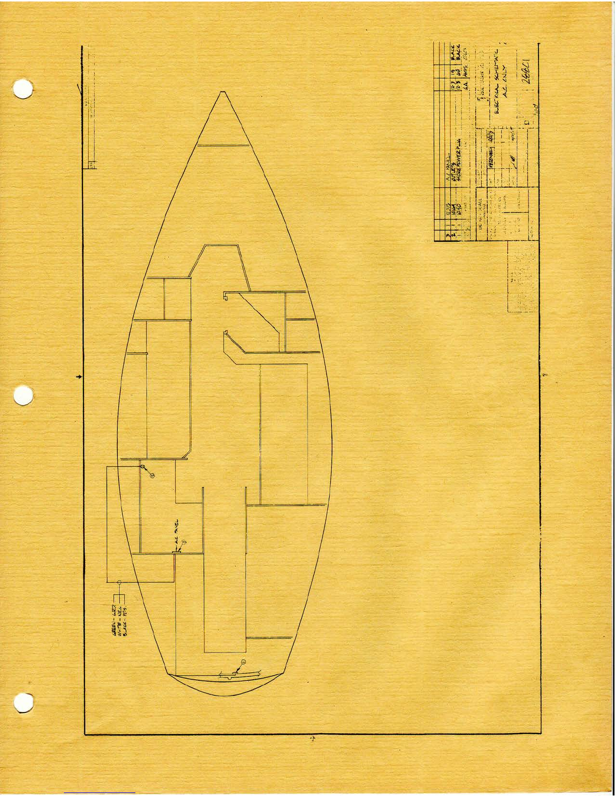
The wiringdiagramin this
sectiori'must,
in some
cases,
beaugmented
bythespecific
enginqwiring
diagramthat
appearsin the Engine
Sectionof thiS
manual.
Alsonotethat
the description of any special
i$ntidnat electrical
accessory
(i.e.,electricbilge pump) will -befound in another,
more
appropriatesection (Plumbing)yet may'appear in this
section's
wiringdiagramor theengine
wiringdiagram.
ln the
event
you make
any
electrical
modificationsto your boat,
be
sure that you follow the wiring diagram or consult a
competent marine electrician.Boat wiring is considerably
differentfrom house
wiringdueto the marineenvironment
andotherconditions
notassociated
with houses.
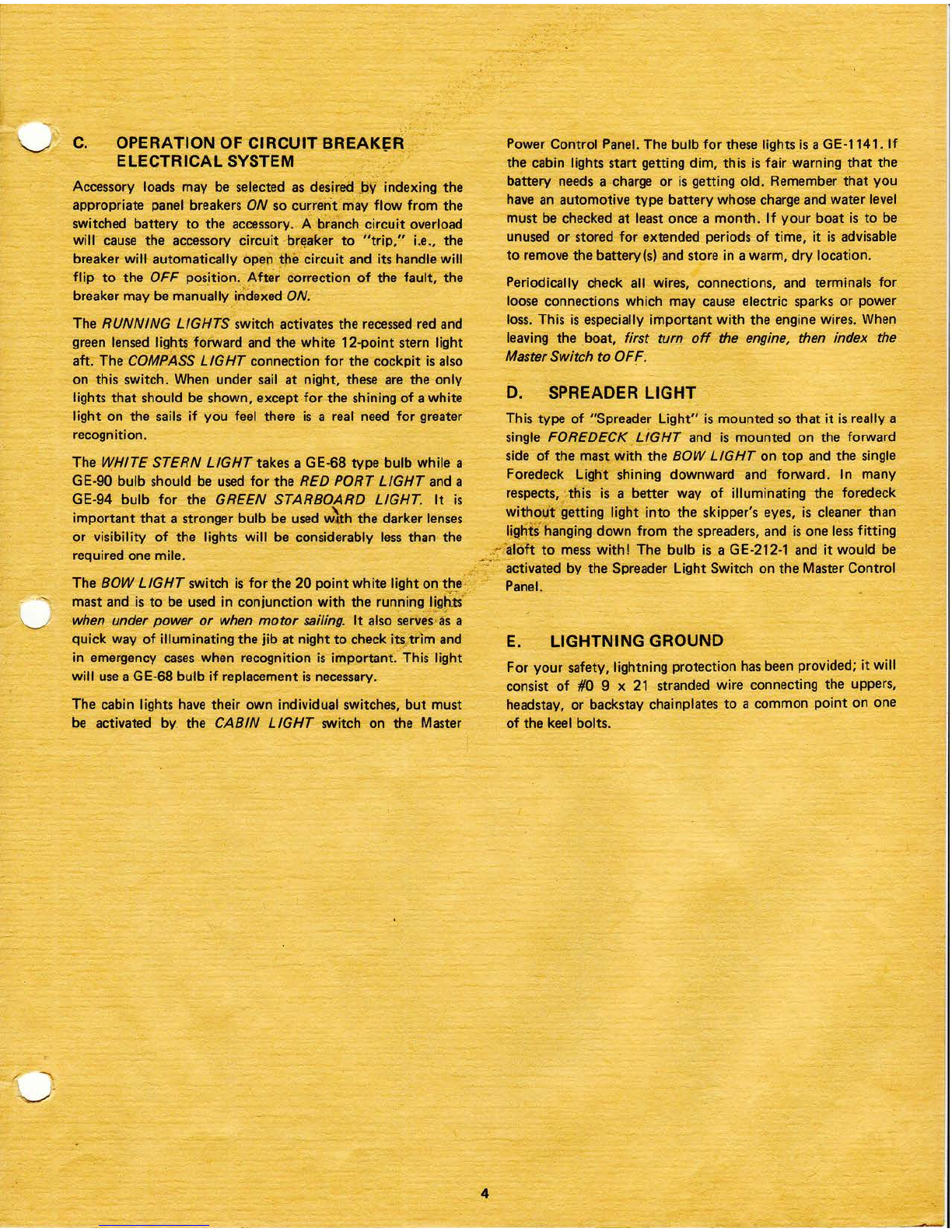
A" BASICCIRCUIT
BREAKER
ELECTRICAL
SYSTEM
TheMaster
Power
Control
Panelfeatures
integrated,
simplified
controlsand circuit breaker
protection
to permit safe
and
efficientoperation
of your boat'selectrical
equipment.
All
panel components
have been carefully selected
for their
provenperformance
in marineapplications.
Thebasic
panel
is
of a plastic
which is inherently
corrosion-resistant
and is
- doubly protected
to optimizeresistanceto the effectsof the
marineenvironment.
Electrical
current
isdirected
froma 12
volt,
30amp
batteryor
batteriesthroughthe Master
Power
Control
Panelfor engine
starting,
battery
charging,
andaccessory
loads.
While
thestandard
installation
isone
battery,manyowners
do
considerablecruising
and
"living
aboard"so
asecond
battery
maybe
added
to meet
theseadditional
electrical
requirements.
Panel
selection
of BAT I or BAT 2 determines
whichof the
two batterieswill be utilized for engine starting and
subsequentcharging.
Beforeactivating
the electricalsystem,
use
theBattery
Condition
Indicatorto ascertain
thecondition
of your
batteries.
The Battery Corhpartmentis under the seat hatch in the
cockpit. Factory installed
batteriesare an automotive
type
whosewaterlevelandcharge
mustbechecked.
B. BATTERY
CONDITION
INDICATOR
This
typeof "indicator"or "meter" istechnically
referredto
asa "suppressedZero
Voltmeter."Notethat calibrations
do
not startat zerobut provide
afull scale
reading
from8 to 10
to 16volts,dependingon themeter.
Below8 or 10
volts,the
battery charge
is so low that terminal voltagereadingsare
meaningless.Approximate
voltagerangeinterpretations
are
as
" follows:
ENGINE NOT RUNNING OR AT IDLE
Below 11 . Very low battery charge
11- 12 Low battery charge
12- 13 Wellchargedbattery
ENGINE RUNNING ABOVE IDLE
'13
to 13% Low charge
rate
13%to 15y2 Alternator & VoltageRegulatorOK
15/zor above Voltage Regulator out of adlustment
It isimportant
for you to understandthat the readingonthe
Battery Condition IndicatorDial is indexedfrom the toggle
test switch position regardlessof the master switch position
unless
it isintheBOTH
position.
Whenthe
MasterSwitch
is
in
theBOTH position
thenthe BatteryCondition
Indicator
Dial
wif
f indicateboth battery conditionsno matter which way the
toggle test switch is indexed. When the MasterSwitch is in
either
theOFF,BAT 1or
BAT2 positions,
the
meterwill read
the condition of the battery towardswhich you index the
ToggleTest
Switch.
Note
that panel
andmeter
illumination
is
also
provided
bythissame
Toggle
Test
Switch.
Before
activatingtheelectricalsystem,
checkthe
condition
of
both batteriesand then select
the strongest
battery for engine
starting. Index the Master Switch to the strong battery,
operate the blower for five minutes, and then start .your
engine.lt will usually
require
about 15 to 30 minutes
of
enginerunning
time to bringthestartingbattery
back
up to
charge.Checkthe ammeter
to assure
thatcharging
isnormal
andwhen the selected
starting
battery has
been
restored,
it is
placed on reserveby switching to the other battery so
subsequentchargingandaccessory
loadswill be confined
to
this second battery. lt is a good practice to bring the first
relected battery up to full chargebefore putting it on reserve
and changingto the secondbattery. Usethe Master
Switch in
BOTH position only tor emergencystarting when both
batteries are low, or for "top off" charging
when both
batteries are near full charge..
When both batteries are
completely
charged,
transferto eitherbattery,
keeping
one
batteryalways
in reserve.
This isespeciallyimportant
when
you realizethatthere
isnowayto start
your inboard
engine
with a deadbattery,
like pushing
a carwhen
you're in the
same
predicament!!
NEVER MOVE THE MASTER STAIITCHTO "OFF"
WHILE THE ENGINE IS RUNNING OR THE
ALTERNATOR
DIODESMAYBE
BURNEDOUT.