iso-9001 KEPCO BOP 2KW-MG User manual

QUICK START GUIDE
KEPCO
KEPCO, INC. 131-38 SANFORD AVENUE FLUSHING, NY. 11355 U.S.A. TEL (718) 461-7000FAX (718) 767-1102
www.kepcopower.com email: hq@kepcopower.com
An ISO 9001 Company.
BOP 2KW
-MG/ME
-MGL/MEL
©2023, KEPCO, INC
Data subject to change without notice 228-1915 REV 3 1
BOP 2KW-MG/ME/MGL/MEL
POWER SUPPLY
This guide gives a brief introduction to the BOP 2KW-MG/ME/MGL/MEL Power supply, shows simple load connections, and
allows you to verify the power supply is working. The guide also shows you how to use the front panel controls to perform the
most commonly used functions.
BOP 2KW models with MG and ME suffixes are identical except that the MG units have a factory-installed GPIB interface and in
the ME units the GPIB interface is replaced with a LAN interface. BOP-MG/ME models with an L suffix have been optimized for
better performance when driving inductive loads such as large magnets or motors. Models with an N suffix have an integral rack
mountable case that replaces the wheeled cabinet Unless otherwise noted this guide applies to all models.
ACCESSING MANUALS. First determine your Firmware Version (see below), then download the applicable BOP 2KW-
MG/ME Operator’s Manual from www.kepcopower.com/support/opmanls.htm#bop-2k
Refer to the BOP 2KW-MG/ME Operator’s Manual for full specifications, installation considerations and operating instructions,
including an Installation/Operation Summary which includes hyperlinked references to detailed procedures, but which can be
printed as a handy reference. The BOP 2KW-MG/ME Operator’s Manual also includes a full description of the digital interfaces
and the SCPI command language.
FIRMWARE VERSION. Refer to www.kepcopower.com/support/bophifirm.htm to determine which firmware version is
installed.
ACCESSING DRIVERS. Drivers are accessed from www.kepcopower.com/drivers/drivers-dl3.htm. BOP 1KW drivers
are applicable to BOP 2KW models. CONTENTS
Description. . . . . . . . . . . . . . . . . . . . . . . . . . . . . . . . . . . . . . . . . . . . . . . . . . . . . . . . . . . . . . . . . . . . . . . . . . . . . . . . . . . . . . . . . . 2
Unpacking. . . . . . . . . . . . . . . . . . . . . . . . . . . . . . . . . . . . . . . . . . . . . . . . . . . . . . . . . . . . . . . . . . . . . . . . . . . . . . . . . . . . . . . . . . . 2
Equipment Supplied. . . . . . . . . . . . . . . . . . . . . . . . . . . . . . . . . . . . . . . . . . . . . . . . . . . . . . . . . . . . . . . . . . . . . . . . . . . . . . . . . . . 2
Safety. . . . . . . . . . . . . . . . . . . . . . . . . . . . . . . . . . . . . . . . . . . . . . . . . . . . . . . . . . . . . . . . . . . . . . . . . . . . . . . . . . . . . . . . . . . . . . 2
Preliminary Operational Check. . . . . . . . . . . . . . . . . . . . . . . . . . . . . . . . . . . . . . . . . . . . . . . . . . . . . . . . . . . . . . . . . . . . . . . . . . . 3
Accessories. . . . . . . . . . . . . . . . . . . . . . . . . . . . . . . . . . . . . . . . . . . . . . . . . . . . . . . . . . . . . . . . . . . . . . . . . . . . . . . . . . . . . . . . . 3
Installation. . . . . . . . . . . . . . . . . . . . . . . . . . . . . . . . . . . . . . . . . . . . . . . . . . . . . . . . . . . . . . . . . . . . . . . . . . . . . . . . . . . . . . . . . . 5
Rack Mounting (N suffix ONLY). . . . . . . . . . . . . . . . . . . . . . . . . . . . . . . . . . . . . . . . . . . . . . . . . . . . . . . . . . . . . . . . . . . . . . 5
Wiring. . . . . . . . . . . . . . . . . . . . . . . . . . . . . . . . . . . . . . . . . . . . . . . . . . . . . . . . . . . . . . . . . . . . . . . . . . . . . . . . . . . . . . . . . . 5
Input Connections. . . . . . . . . . . . . . . . . . . . . . . . . . . . . . . . . . . . . . . . . . . . . . . . . . . . . . . . . . . . . . . . . . . . . . . . . . . . . . . . 5
Load Connections. . . . . . . . . . . . . . . . . . . . . . . . . . . . . . . . . . . . . . . . . . . . . . . . . . . . . . . . . . . . . . . . . . . . . . . . . . . . . . . . 5
Local Sensing (Factory Default). . . . . . . . . . . . . . . . . . . . . . . . . . . . . . . . . . . . . . . . . . . . . . . . . . . . . . . . . . . . . . . . . . . . . . 5
Remote Sensing Select. . . . . . . . . . . . . . . . . . . . . . . . . . . . . . . . . . . . . . . . . . . . . . . . . . . . . . . . . . . . . . . . . . . . . . . . . . . . 5
Analog I/O Connections. . . . . . . . . . . . . . . . . . . . . . . . . . . . . . . . . . . . . . . . . . . . . . . . . . . . . . . . . . . . . . . . . . . . . . . . . . . . 5
Trigger Connections. . . . . . . . . . . . . . . . . . . . . . . . . . . . . . . . . . . . . . . . . . . . . . . . . . . . . . . . . . . . . . . . . . . . . . . . . . . . . . . 5
GPIB Connections (MG SUFFIX). . . . . . . . . . . . . . . . . . . . . . . . . . . . . . . . . . . . . . . . . . . . . . . . . . . . . . . . . . . . . . . . . . . . 5
LAN Connections (ME SUFFIX ONLY). . . . . . . . . . . . . . . . . . . . . . . . . . . . . . . . . . . . . . . . . . . . . . . . . . . . . . . . . . . . . . . . 5
Finding Kepco Power Supplies on the LAN. . . . . . . . . . . . . . . . . . . . . . . . . . . . . . . . . . . . . . . . . . . . . . . . . . . . . . . . . . . . . 6
RS 232 Connections. . . . . . . . . . . . . . . . . . . . . . . . . . . . . . . . . . . . . . . . . . . . . . . . . . . . . . . . . . . . . . . . . . . . . . . . . . . . . . 6
Operation. . . . . . . . . . . . . . . . . . . . . . . . . . . . . . . . . . . . . . . . . . . . . . . . . . . . . . . . . . . . . . . . . . . . . . . . . . . . . . . . . . . . . . . . . . . 6
Turning The Power Supply On. . . . . . . . . . . . . . . . . . . . . . . . . . . . . . . . . . . . . . . . . . . . . . . . . . . . . . . . . . . . . . . . . . . . . . . 6
Accessing the Menus. . . . . . . . . . . . . . . . . . . . . . . . . . . . . . . . . . . . . . . . . . . . . . . . . . . . . . . . . . . . . . . . . . . . . . . . . . . . . . 6
How to Modify a Parameter. . . . . . . . . . . . . . . . . . . . . . . . . . . . . . . . . . . . . . . . . . . . . . . . . . . . . . . . . . . . . . . . . . . . . . . . . 7
Adjusting LCD Brightness, contrast and Background . . . . . . . . . . . . . . . . . . . . . . . . . . . . . . . . . . . . . . . . . . . . . . . . . . . . . 7
Enabling/Disabling Audible Beeps . . . . . . . . . . . . . . . . . . . . . . . . . . . . . . . . . . . . . . . . . . . . . . . . . . . . . . . . . . . . . . . . . . . 7
Setting Voltage or Current Mode . . . . . . . . . . . . . . . . . . . . . . . . . . . . . . . . . . . . . . . . . . . . . . . . . . . . . . . . . . . . . . . . . . . . 7
Programming Voltage or Current and Associated Protect Limits . . . . . . . . . . . . . . . . . . . . . . . . . . . . . . . . . . . . . . . . . . . 11
Software Limits. . . . . . . . . . . . . . . . . . . . . . . . . . . . . . . . . . . . . . . . . . . . . . . . . . . . . . . . . . . . . . . . . . . . . . . . . . . . . . . . . 12
Changing Main Channel Software limit.. . . . . . . . . . . . . . . . . . . . . . . . . . . . . . . . . . . . . . . . . . . . . . . . . . . . . . . . . . . 12
Determining How the Unit Responds when Output is OFF (Load Type) . . . . . . . . . . . . . . . . . . . . . . . . . . . . . . . . . . . . . 12
Configure Load Type. . . . . . . . . . . . . . . . . . . . . . . . . . . . . . . . . . . . . . . . . . . . . . . . . . . . . . . . . . . . . . . . . . . . . . . . . . . . . 14
Enabling/disabling Output Power. . . . . . . . . . . . . . . . . . . . . . . . . . . . . . . . . . . . . . . . . . . . . . . . . . . . . . . . . . . . . . . . . . . . 14
Additional Features. . . . . . . . . . . . . . . . . . . . . . . . . . . . . . . . . . . . . . . . . . . . . . . . . . . . . . . . . . . . . . . . . . . . . . . . . . . . . . . . . . . 14

2228-1915 REV 3 032723
KEPCO, INC. 131-38 SANFORD AVENUE FLUSHING, NY. 11355 U.S.A. TEL (718) 461-7000FAX (718) 767-1102
www.kepcopower.com email: hq@kepcopower.com
I — DESCRIPTION.
The BOP 2KW-MG/ME Series hereafter referred to as
BOP, are true 4-quadrant programmable voltage and
current power supplies, meaning they are capable of
both sourcing and sinking power (see Figure 1). These
bipolar power supplies pass smoothly through zero
without switching to provide true ± voltage and ± cur-
rent. These BOP power supplies use switch mode
technology for low dissipation. A bi-directional, isolat-
ing, a-c input power factor correcting (PFC) circuit
recuperates energy sinked from an active load and
sends it back into the line to maintain low dissipation.
These BOP power supplies are controlled digitally from
a menu-driven front-panel keypad or one of the remote
digital interfaces (GPIB or RS 232 on MG models, LAN
or RS 232 on ME models) to set voltage and current
and the four protection limits (+voltage, –voltage, +cur-
rent and –current.) A front panel rotary adjuster allows
real-time adjustment of the output. A large LCD dis-
plays the mode of operation, the settings, and the
actual output voltage and current. Additionally, these
BOP models can be remotely controlled by an analog
±10V input for the main channel (voltage or current),
and a +1 to +10V input for the limit channels.
BOP models are suitable for driving inductive loads
such as large magnets or motors, and for exercising
batteries. They are also suitable for characterizing
solar cell arrays, and powering many electrochemical
reactions. Models with L suffix have been optimized for
exceptionally low current ripple and noise and
improved stability (drift and temperature), making them
ideal for driving inductive loads such as large magnets
or motors. Models with an N suffix have an integral
rack mountable case that replaces the wheeled cabinet
II — UNPACKING.
This instrument has been thoroughly inspected and
tested prior to packing and is ready for operation. BOP
2KW models are shipped in a special shipping crate,
Kepco P/N 213-0104, except N option units are
shipped in a cardboard box. CAUTION: N option units
weigh over 110 lbs and require two people to lift
safely. For units in a crate refer to the unpacking/pack-
ing instructions shown in Figure 12 on page 18 of this
manual to unpack the unit without damaging the ship-
ping crate. It is recommended that the shipping crate
be retained for future shipment when needed. Once the
unit is unpacked, a hoist is recommended to lift the unit
from the base (four holes for eyebolts are provided at
the top of the cabinet). After careful unpacking, inspect
for shipping damage before attempting to operate. Per-
form the “Installation.” on page 5. If any indication of
damage is found, file an immediate claim with the
responsible transport service.
.
III — EQUIPMENT SUPPLIED.
None. IV — SAFETY. See Table 2
TABLE 1. BOP 2KW-MG/ME MODEL PARAMETERS
Model (1) d-c Output Range Closed Loop Gain
Voltage (2)
(V d-c) Current
(A d-c) Voltage Channel
GV(V/V) Current Channel
GI(A/V)
2000 WATT MODELS
BOP 6-250MG/ME (3) 0 to ±6 0 to ±250 0.6 25.0
BOP 10-200MG/ME/MGL/MEL 0 to ±10 0 to ±200 1.0 20.0
BOP 12-125MG/ME 0 to ±12 0 to ±125 1.2 12.5
BOP 20-100MG/ME/MGL/MEL 0 to ±20 0 to ±100 2.0 10.0
BOP 25-80MG/ME 0 to ±25 0 to ±80 2.5 8.0
BOP 36-56MG/ME/MGL/MEL 0 to ±36 0 to ±56 3.6 5.6
BOP 40-50MG/ME/MGL/MEL 0 to ±40 0 to ±50 4.0 5.0
BOP 50-40MG/ME/MGL/MEL 0 to ±50 0 to ±40 5.0 4.0
BOP 72-28MG/ME/MGL/MEL 0 to ±72 0 to ±28 7.2 2.8
BOP 100-20MG/ME 0 to ±100 0 to ±20 10.0 2.0
BOP 144-14MG/ME 0 to ±144 0 to ±14 14.4 1.4
BOP 200-10MG/ME 0 to ±200 0 to ±10 20.0 1.0
(1) Models with MG suffix include GPIB and RS 232 digital interfaces. Models with ME suffix include LAN and RS 232 digital interfaces.
(2) When connecting active loads,the steady-state voltage of the active load must not exceed the maximum voltage rating of the BOP. Otherwise the overvolt-
age protection will shut down the power supply.
(3) This model can handle 1.5kW maximum.

032723 228-1915 REV 3 3
KEPCO, INC. 131-38 SANFORD AVENUE FLUSHING, NY. 11355 U.S.A. TEL (718) 461-7000FAX (718) 767-1102
www.kepcopower.com email: hq@kepcopower.com
V — PRELIMINARY OPERATIONAL CHECK.
A simple operational check after unpacking and before
equipment installation is advisable to ascertain whether
the power supply has suffered damage resulting from
shipping.
1. With both control and power boost section
POWER switches set to off position, connect the
power supply to source power (see “Input Con-
nections.” on page 5).
2. With no load connected, set both control and
power boost section POWER switches to the ON
position. Each time the unit is turned on an inter-
nal self-test is performed. If all tests pass, the unit
goes into the default mode. If a failure occurs, the
failure is displayed. Figure 5 shows the factory-
configured power on defaults displayed on the
LCD.
3. Connect a digital voltmeter (DVM) (resolution and
accuracy of 0.01% or better) to the OUT S and
COM S terminals at the BOP 2K rear panel termi-
nal block.
4. Use the keypad to enter the rated maximum volt-
age of the power supply (e.g., enter 144 for a
model BOP 144-14MG) and press ENTER. If
STANDBY indicator is lit, press STANDBY key.
5. Verify DVM voltage reading agrees with pro-
grammed voltage within 0.03% of rated maximum
voltage and agrees with displayed voltage on
LCD within 0.05% of rated maximum voltage.
VI — ACCESSORIES. See Table 3.
TABLE 2. SAFETY SYMBOLS
SYMBOL MEANING SYMBOL MEANING
CAUTION: RISK OF ELECTRIC SHOCK. WARNING INDICATES THE POSSIBILITY OF BODILY
INJURY OR DEATH.
CAUTION: REFER TO REFERENCED PROCE-
DURE. CAUTION INDICATES THE POSSIBILITY OF EQUIP-
MENT DAMAGE.
!
TABLE 3. ACCESSORIES
ITEM FUNCTION PART NUMBER
Mating Connector, Trigger Mates with Trigger port. 142-0527 (Kepco)
SP2501 (CUI Stack)
IEEE 488 Cable, (1 meter long) For MG models only. Connects BOP power supply to GPIB bus. SNC 488-1
IEEE 488 Cable, (2 meter long) For MG models only. Connects BOP power supply to GPIB bus. SNC 488-2
IEEE 488 Cable, (4 meter
longs) For MG models only. Connects BOP power supply to GPIB bus. SNC 488-4
RS 232 Cable Kit Contains RJ11 to RJ45 Patch cord, RJ 45 Patch cord, two RS 232 adapters,
one with male pins to connect to DTE equipment and one with female pins to
connect to a PC (personal computer), two RS 232 Loop Back test Connec-
tors (one 6-pin and one 8-pin) to test RS 232 communication and aid in iso-
lating RS 232 communication problems.
KIT 219-0436
RS 232 Adapter (Male pins) Allows RS 232 port to be connected to DTE equipment. (Supplied in KIT
219-0436.) 142-0487
(L-COM RA098M)
RS 232 Adapter (Female pins) Allows RS 232 port to be connected to a PC (personal computer). (Supplied
in KIT 219-0436.) 142-0506
(L-COM RA098F)
15-pin DSUB Connector Mating connector for Analog input connector A2A5J6 Dsub 15 pin hood
Dsub 15 pin male
108-0374
(Tyco-Amp 207470-1)
142-0449
(Amphenol 17S-DA15P)
IDC 6-pin connector Mating connector for RS-232 PORT, connector A1J5 and PROTECTION
EXT. PORT, connector A2A5J7 142-0536
(Amphenol 5-555176-3)
Heat Sink Provides adequate cooling for calibration sense resistors. 136-0451

4228-1915 REV 3 032723
KEPCO, INC. 131-38 SANFORD AVENUE FLUSHING, NY. 11355 U.S.A. TEL (718) 461-7000FAX (718) 767-1102
www.kepcopower.com email: hq@kepcopower.com
FIGURE 1. BOP OUTPUT CHARACTERISTICS

032723 228-1915 REV 3 5
KEPCO, INC. 131-38 SANFORD AVENUE FLUSHING, NY. 11355 U.S.A. TEL (718) 461-7000FAX (718) 767-1102
www.kepcopower.com email: hq@kepcopower.com
VII — INSTALLATION.
RACK MOUNTING (N SUFFIX ONLY). N Suf-
fix models may be mounted in a 19-inch wide rack as
described in the Operator Manual CAUTION: Before
rack mounting models with N suffix, refer to Opera-
tor Manual for safety precautions.
WIRING. A cable access opening is provided at the
left side of the control section rear panel (see Figure
10) to allow cable connections through the cover for
Analog control, Trigger, RS-232, GPIB, (MG models)
and LAN (ME models).. For convenience when making
connections to the control section rear panel (Figure 6),
remove control section rear cover (four screws), thread
the cable(s) through the access opening and connect
to rear panel as needed, then reassemble rear cover.
INPUT CONNECTIONS. Source power is con-
nected to the power supply via three-wire input power
connected to the three Eurostyle terminal blocks on the
rear panel. This power supply operates with an input a-
c voltage in the range of 176 - 264V/47 - 63Hz without
any need of range/frequency selection. The unit can be
supplied from either a single phase, or between phases
of a 3-phase a-c system as long as the input voltage is
within the range specified above. The user must pro-
vide a properly sized and rated mains lead (line cord)
and service with a current rating compatible with the
rated input current (19A a-c maximum).
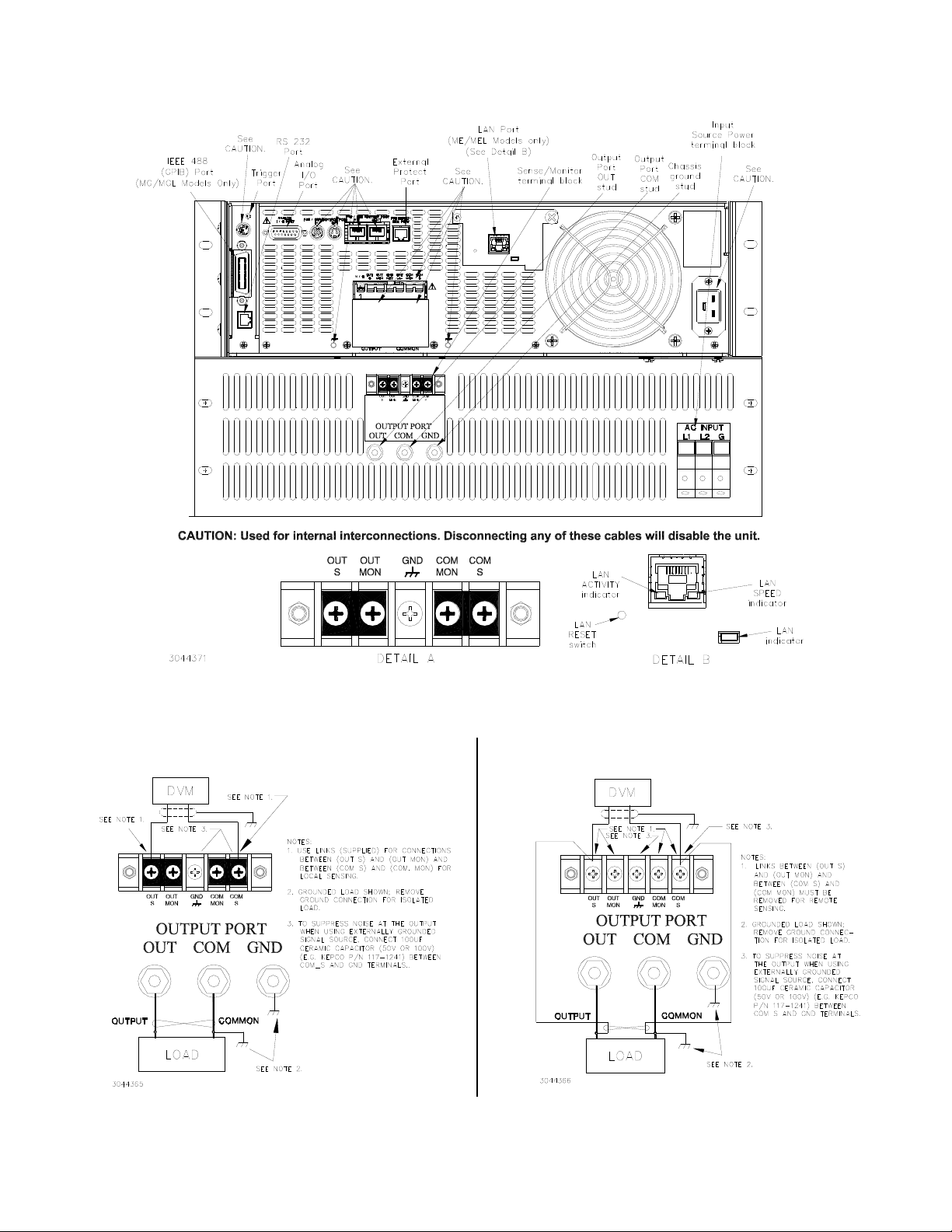
LOAD CONNECTIONS.
Power connections re-
quire wires that are properly rated for the nominal output
current of the unit.
Connect the load to the OUTPUT
and COMMON power terminals on the BOP 2KW Out-
put Terminal Block on the rear panel (see Figure 10).
OUT S and COM S terminals of the Sense/Monitor Ter-
minal block are for connection of remote sensing leads
(after removing the factory-installed local sensing
links). NOTE: Output Sense lines must be con-
nected for proper operation, either locally, or at the
load (remote). Also use OUT S and COM S to monitor
voltage at the load using external equipment such as a
DVM, oscilloscope, etc. Use OUT MON and COM
MON to monitor voltage at the BOP output. Use twisted
wire pairs or wires that are tied together for both output
power and output sensing connections.
It is critical that configurations comprised of BOP, load,
and external programming devices, have a single
earth-ground point. Observe the following caution and
refer to the applicable BOP 2KW-MG Operator Manual
for earth-ground recommendations. Failure to
observe this caution will void the warranty!
CAUTION: Never connect both the load
terminal tied to the BOP COM terminal
and the programming device common
to earth-ground. This compromises
accuracy and will cause catastrophic
damage to the BOP if the connection
between BOP COM and the load termi-
nal tied to earth-ground is lost.
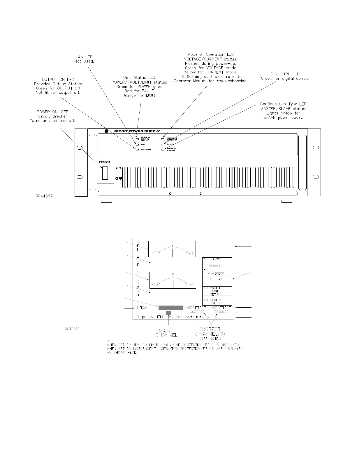
LOCAL SENSING (FACTORY DEFAULT).
Unit is shipped with local sensing links installed: OUT S
connected to OUT MON and COM MON connected to
COM S at the BOP 2KW Sense/Monitor Terminal Block
(see Figures 7A and 10).
REMOTE SENSING SELECT. First remove the
factory-installed local sensing links between OUT S
and OUT MON and between COM MON and COM S at
the BOP 2KW Sense/Monitor Terminal Block. Then
connect OUT S and COM S lines from the BOP 2KW
Sense/Monitor Terminal Block to the load (see Figure
7B) using #22 AWG wire, twisted pair.
ANALOG I/O CONNECTIONS. The Analog I/O
Port connector, located on the control section rear
panel of the BOP 2KW power supply (see Figure 6),
provides access to analog programming inputs which
can control the mode of operation (voltage or current),
output voltage or current, and establish positive and
negative voltage and current limits. An output analog
corresponding to output current is also provided. Refer
to Operator’s manual for details.
TRIGGER CONNECTIONS. The Trigger Port
(see Figure 6) provides for an external trigger input for
use with SCPI *TRG and TRIG commands. Refer to
Operator’s manual for details.
GPIB CONNECTIONS (MG SUFFIX). Your
computer must have a GPIB interface card installed.
Connect the power supply to the computer’s GPIB
interface card. Use a standard GPIB interface cable at
the GPIB port on the rear panel (see Figure 6).
The default GPIB address is 6; refer to the Operator’s
Manual to change it.
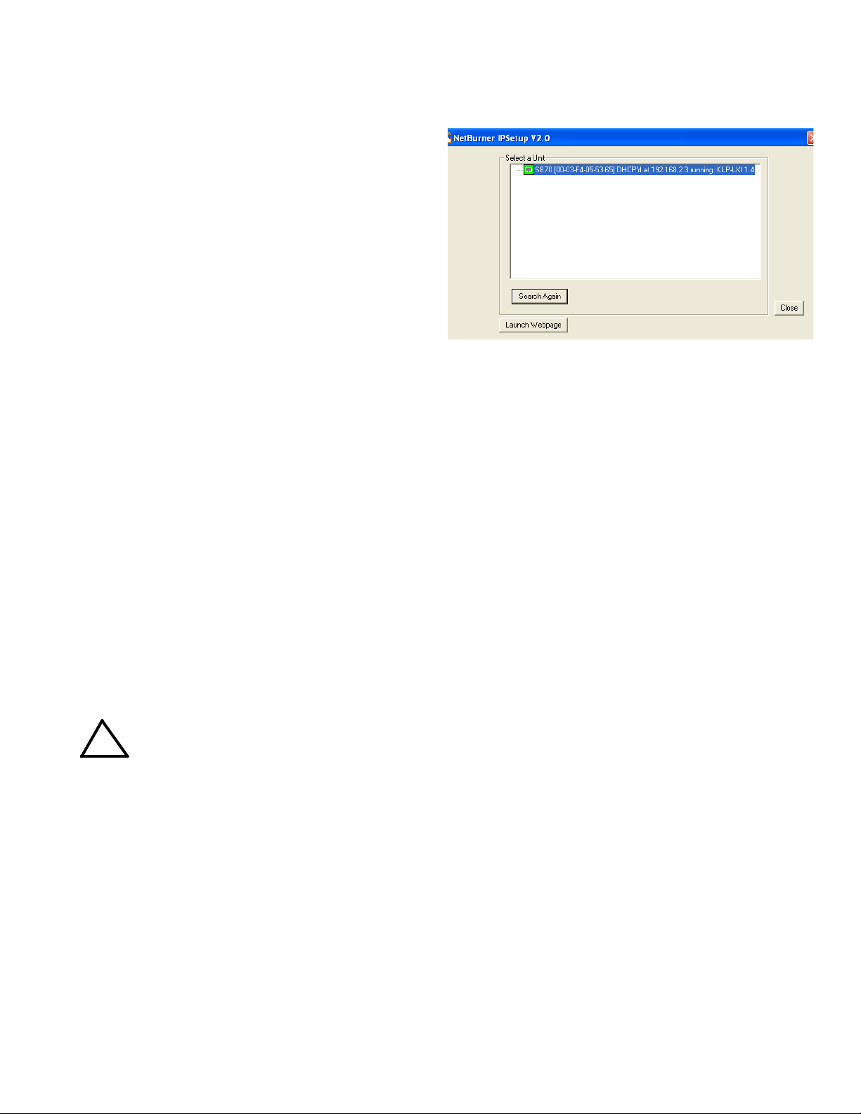
LAN CONNECTIONS (ME SUFFIX ONLY).
Connect the BOP 2KW to a Microsoft Windows-based
computer via the LAN connector (see Figure 6). Use a
standard ethernet cable whether using a router or hub,
or connecting the BOP 2KW directly to a computer.
The BOP 2KW-ME is Auto-MDI-X enabled and does
not require a crossover cable for direct connection. For
Unix and Safari connections see full Operator Manual
(refer to “Accessing Manuals.” on page 1).
!

6228-1915 REV 3 032723
KEPCO, INC. 131-38 SANFORD AVENUE FLUSHING, NY. 11355 U.S.A. TEL (718) 461-7000FAX (718) 767-1102
www.kepcopower.com email: hq@kepcopower.com
FINDING KEPCO POWER SUPPLIES ON
THE LAN. The PS Find utility can be downloaded
from the Kepco web site at:
www.kepcopower.com/drivers/drivers-dl3.htm#bop1k
This utility finds all operational Kepco power supplies
connected to the LAN and then shows the MAC and IP
addresses of the models found.
To run the utility from your PC download the psfind.zip
file to your computer. Extract psfind.exe from the zip
file to a location of your choice, then double-click
psfind.exe to run the application. A separate window
opens as shown in Figure 2. Once the search is com-
pleted, all found units are displayed in the Select a Unit
window (the MAC address appears in parentheses). If
you do not see your device in the Select a Unit window
or if the icon to the left of the selected instrument is red
(not green), make sure it is turned on and connected to
the network, then click the Search Again button.
FIGURE 2. PS FIND SCREEN
RS 232 CONNECTIONS. Connect the BOP 2KW
to a modem using a Null Modem patch cable at the RS
232 port located on the rear panel (See Figure 6). A
VIII — OPERATION.
Refer to Figures 3 and 4 for the function of front panel
controls and indicators for the control and power
boost sections, respectively.
Additional features covered in the Operator Manual
are: Quick Boot (eliminating the power- up displays),
use of the internal relay, operation via the LAN inter-
face or analog signals and setting coarse/fine adjust-
ment preference of the VOLTAGE and CURRENT
controls. An Installation/Operation Summary is also
included in the Operator Manual. The Operator Manual
also covers the GPIB, Ethernet and RS 232 interfaces,
including the use of the drivers downloadable from:
www.kepcopower.com/drivers/drivers-dl3.htm#bop1k.
TURNING THE POWER SUPPLY ON.
CAUTION:
DO NOT repeatedly toggle the cir-
cuit breaker/switch as this may
damage the unit.
Set POWER ON/OFF circuit breaker/switch on front
panel to ON. If actuator does not lock when released,
wait a few seconds before trying again. The circuit
breaker is “trip-free” design; if overload exists, contacts
cannot be held closed by actuator.
• When the power supply is turned on, it per-
forms a brief self-test that includes testing the
three processors (analog, interface and dis-
play) and an inter-module test, then displays
the power-up screen (see Figure 5). If an error
is detected, the FAULT indicator will light,
information about the error will be briefly dis-
played on the LCD.
• If the unit powers up in REMOTE mode, press
!to set the unit to LOCAL mode.
• If the display is not viewable, press #twice.
The display will cycle through the range of
contrast settings. Press #again to lock in
the preferred contrast.
ACCESSING THE MENUS. From the power-up
screen, pressing the Function keys indicated on the
LCD opens the associated menu. The menu opened
may list submenus that may be opened either directly
by pressing the associated Function keys, or by high-
lighting an item on the list and pressing the View/Mod-
ify function key. Menus and submenus will display a list
of parameters, with the top one highlighted. The func-
tion key assignments can vary, but generally offer the
following choices:
•!allows the highlighted parameter to be
viewed or modified. After changing the param-
eter, the following choices are available: $-
SAVE or ENTER to save the change, %-
EXIT to abort the change and exit to the previ-
ous menu.
•@- RESTORE DEFAULT restores factory
defaults for the parameters displayed (except
for GPIB address). The factory defaults may
be saved as power-up defaults by pressing
$.
!

032723 228-1915 REV 3 7
KEPCO, INC. 131-38 SANFORD AVENUE FLUSHING, NY. 11355 U.S.A. TEL (718) 461-7000FAX (718) 767-1102
www.kepcopower.com email: hq@kepcopower.com
•#- The function varies, depending on the
menu. In most cases #is used to abort a
change without applying the modified setting.
From the power-up screen #is used to
adjust contrast. In the Revisions/TEST sub-
menu of the General Setup Menu, #is used
to execute a test.
•$- SAVE FOR POWER-UP Saves the con-
figuration shown as a power-up setting so the
changes will not be lost when the unit is
turned off.
•%- APPLY EXIT applies the current
(changed) setting without saving for power-up
and exits to the previous menu or to the
power-up screen, EXIT leaves the current
menu without saving or applying changes.
HOW TO MODIFY A PARAMETER.
First access the parameter by accessing the proper
menu as described above. To modify a parameter
listed in a menu or submenu, proceed as follows:
1. Highlight the parameter using the Yand Ukeys.
2. When the desired choice is highlighted, press !
to modify the active setting. The choices are dis-
played with the active setting highlighted. In the
case of numerals, the units digit is highlighted.
• To change a numeric setting, press the num-
ber keys, then press ENTER to program the
numbers entered. Use the CLEAR key to
clear numbers entered and start over. The
ADJUST control can also be used to incre-
ment or decrement the highlighted digit.
Pressing ADJUST while rotating adjusts the
least significant digit. If the output is on (unit
not in Standby) changes made using the
ADJUST control are immediately applied to
the output.
• For alphanumeric characters use multiple
presses of the number keys for letters or sym-
bols: 0(space), 1(+, –, /), 2(ABC), 3
(DEF), 4(GHI), 5(JKL), 6(MNO). 7
(PQRS), 8(TUV), 9(WXYZ). Use the T
key to highlight the next character. As an alter-
native, the Uor Ykeys or ADJUST control
will scroll through numbers, and letters and
symbols. Use the CLEAR key to clear the
entire alphanumeric field and start over
3. Press $to apply the change and return to the
menu (to change another parameter, repeat steps
1 and 2). To abort (return to the menu without
applying the change), press %.
NOTE:Press HELP key for more information,
press HELP again to see multiple
screens; press CLEAR key to exit the
help screen.
ADJUSTING LCD BRIGHTNESS, CON-
TRAST AND BACKGROUND From the power-
up screen, (Figure 5), press #twice to initiate con-
trast adjustment. The contrast gradually alternates
between light and dark. When the contrast is accept-
able, press #to apply the change and exit contrast
adjust. Use the Tand Rkeys for fine adjustment of
contrast. Contrast can also be adjusted from the
power-up screen by pressing #once, then pressing
Tand Ras needed for fine adjustment.
To change the background, press #from the power-
up screen, Highlight Background, press !, highlight
Black or White, then $to save. Press $exit and
save for power-up or %to apply the changes (without
saving for power-up) and exit.
ENABLING/DISABLING AUDIBLE BEEPS
From the power-up screen, press #, then modify the
setting. Even though audible beeps are set to off, the
beeps will still sound upon power-up or detection of a
power supply fault.
SETTING VOLTAGE OR CURRENT MODE
The BOP uses two separate channels, one to set out-
put voltage or current and one to set the corresponding
protection limit. The main channel is determined by the
MODE key (in local mode) which alternately selects
either Voltage mode or Current mode or by SCPI com-
mand (in digital remote mode). The protection channel
is determined automatically by the main channel
selected. When Voltage mode is selected, the current
protection channel is active, and when Current mode is
selected, the Voltage protection channel is active.

8228-1915 REV 3 032723
KEPCO, INC. 131-38 SANFORD AVENUE FLUSHING, NY. 11355 U.S.A. TEL (718) 461-7000FAX (718) 767-1102
www.kepcopower.com email: hq@kepcopower.com
FIGURE 3. BOP 2KW SERIES, CONTROL SECTION, FRONT PANEL CONTROLS AND INDICATORS
E
N
T
E
R

032723 228-1915 REV 3 9
KEPCO, INC. 131-38 SANFORD AVENUE FLUSHING, NY. 11355 U.S.A. TEL (718) 461-7000FAX (718) 767-1102
www.kepcopower.com email: hq@kepcopower.com
FIGURE 4. BOP 2KW SERIES, POWER BOOST SECTION, FRONT PANEL CONTROLS AND INDICATORS
FIGURE 5. POWER-UP SCREEN SHOWING GRAPHIC METERS
VOLTAGE
SOURCE
0.0402
0.0000
ANALOG VOLTMETER
DIGITAL VOLTMETER
ANALOG AMMETER
DIGITAL AMMETER
HIGHLIGHT TO CHANGE
LOCAL/REMOTE
OPERATING
INFORMATION
SOFTWARE
FUNCTION KEY
DESCRIPTIONS
STATUS
ACTIVE SETTINGS
MESSAGES
VOLTAGE
0000
0.

10 228-1915 REV 3 032723
KEPCO, INC. 131-38 SANFORD AVENUE FLUSHING, NY. 11355 U.S.A. TEL (718) 461-7000FAX (718) 767-1102
www.kepcopower.com email: hq@kepcopower.com
FIGURE 6. BOP 2KW SERIES, REAR PANEL VIEW (CONTROL SECTION REAR
COVER REMOVED), LINKS INSTALLED FOR LOCAL SENSING
FIGURE 7. LOAD CONNECTION, TYPICAL
A. LOCAL SENSING B. REMOTE SENSING

032723 228-1915 REV 3 11
KEPCO, INC. 131-38 SANFORD AVENUE FLUSHING, NY. 11355 U.S.A. TEL (718) 461-7000FAX (718) 767-1102
www.kepcopower.com email: hq@kepcopower.com
FIGURE 8. BOP 2KW SERIES ( N OPTION), REAR PANEL VIEW (CONTROL SECTION,
LINKS INSTALLED FOR LOCAL SENSING
PROGRAMMING VOLTAGE OR CURRENT
AND ASSOCIATED PROTECT LIMITS From
the power-up screen the settable voltage/current
parameters are displayed at the bottom of the LCD
above the HELP message. Use Yor Uto highlight
the main or protect channel.
1. To verify that the unit is configured for internal ref-
erences press $from the power-up screen and
verify that Reference Input and Protection Limit
are set to Internal, and External Mode is set to
Disable. If necessary to change a setting, use Y
or Uto highlight the parameter, and press !to
modify. Highlight the desired selection and press
$to save, then press $to save for power-up
or %to exit. If analog programming is desired,
refer to Operator’s Manual.
2. Verify that the load type has been configured
properly to ensure that the unit behaves as
expected when the output is off (see “Max/Min
Setting Menu” on page 13 9 for details).
3. Press MODE key to select the main channel
(VOLTAGE or CURRENT); the associated PRO-
TECT channel is automatically selected and dis-
played.
4. Set the output on or off as desired using the
STANDBY key. The output is off (disabled) when
the STANDBY indicator is lit, on (enabled) when
not lit.
5. Use Yor Uto highlight the main channel. There
are two ways to program the output in local mode.
These methods can be used either when the out-
put is disabled (STANDBY indicator lit) or
enabled.
S
COM
MON
OUT
OUT
S
GND
MON
COM

12 228-1915 REV 3 032723
KEPCO, INC. 131-38 SANFORD AVENUE FLUSHING, NY. 11355 U.S.A. TEL (718) 461-7000FAX (718) 767-1102
www.kepcopower.com email: hq@kepcopower.com
WARNING:
When the ADJUST control is
rotated, the active parameter is
immediately effective if the output
is enabled (on = STANDBY indica-
tor not lit). The voltage/current
applied to the load changes as the
ADJUST control is rotated.
• Use the ADJUST control to increase or
decrease the main channel setting (e.g., volt-
age when the unit is in voltage mode). Start
with the most significant digit of the desired
value, then use Tto highlight the next digit.
For fine adjustment press the ADJUST control
in while rotating the knob to modify the least
significant digit.
• Enter the desired value on the keypad using
the number keys. For example, to program the
BOP to 75.8V, press the following keys in
order 75.8 then press ENTER. For fine
adjustment use Y, and Uto modify the least
significant digit. To correct the entry before
activation press the CLEAR key to set the
value to zero and start over. When the desired
value is displayed, press ENTER. This causes
the new value to appear at the output and be
applied to the load if the output is enabled.
6. To program the corresponding Protect channel,
press Yor Uas necessary to highlight the Pro-
tect channel. Then set the value using either of
the two methods described above. If the Protect
Entry setting is set to Independent, separate
entries for the positive and negative protect chan-
nel are possible. Otherwise the value entered is
applied to both positive and negative protect
channels.
NOTE: The BOP can be configured to show
the protection limits as either a single
value that applies to both protection
channels or show individual settings
for positive and negative protection
limits. Only voltage protection limits
are available when in current mode;
only current limits are available in volt-
age mode. See Operator’s Manual for
details.
SOFTWARE LIMITS. Software limits prevent pro-
gramming of the main channel or the Protect channel
beyond the software limit value. Refer to Operator’s
Manual for a full explanation of software limits.
Changing Main Channel Software limit.
This procedure allows the user to determine the maxi-
mum value of voltage or current that can be pro-
grammed.
1. Press %from the power-up screen to enter the
General Setup menu, then highlight Max/Min Set-
tings.
2. Press !to enter the Max/Min Settings submenu
(Figure 9). (If a Password is required, see Opera-
tor’s Manual for instructions.)
3. Highlight the voltage or current max/min value
and press !to change it. Software limits are
absolute values (do not use minus sign for nega-
tive limits). Use number keys to change the set-
ting, then $to save.
4. When complete, press $to save for power-up,
#to abort, or %to apply the changes (without
saving for power-up) and exit.
5. Upon return to the power-up screen, the main
channel (voltage or current) is compared against
the main channel limits in effect. If the main chan-
nel exceeds the limit, it is set to zero.
6. Highlight the ±CPROTECT or ±VPROTECT max/
min value and press !to change it. Software
limits are absolute values (do not use minus sign
for negative limits). Use number keys to change
the setting. Press $to save, or %to abort.
7. When complete, press $to save for power-up,
or #to abort, or %to apply the changes (with-
out saving for power-up) and exit.
Upon return to the power-up screen, the new protection
limit (voltage or current) is compared against the pro-
tection limits in effect. If the new protection limit setting
is below the existing setting for the protection limit, the
protection channel (voltage or current) is set to zero.
DETERMINING HOW THE UNIT RESPONDS
WHEN OUTPUT IS OFF (LOAD TYPE) The
BOP supports three Load Type selections (see Table 4)
which determine how the power supply responds when
the output is off: ACTIVE, RESISTIVE and BATTERY.
The Load Type selection does not affect the settings of
the power supply for ON state; it only affects the mode
of operation, main internal reference level and the pro-
tection levels during the OFF state.

032723 228-1915 REV 3 13
KEPCO, INC. 131-38 SANFORD AVENUE FLUSHING, NY. 11355 U.S.A. TEL (718) 461-7000FAX (718) 767-1102
www.kepcopower.com email: hq@kepcopower.com
WARNING
For inductive loads, and especially
superconducting magnet type
loads, the inherent offset of the
BOP in the OFF state may generate
significant current in the circuit. A
properly rated switch in parallel
with a resistor must be connected
between the power supply and the
load. The switch must be open and
the BOP front panel LCD must read
0V, 0A before removing or installing
connections between BOP and
load.
Active. Active mode (default setting) is necessary for
the power supply to function properly and safely with
inductive loads and constant-current-type active elec-
tronic loads. Active mode can also be used with resis-
tive loads. Table 4 indicates how the power supply
responds to a command to go from Output ON to OFF.
When the output is disabled, the unit is set to voltage
mode, voltage is set to zero and both current protect
and voltage limit are set to maximum. When the unit is
enabled, the pre-existing settings for voltage, current
protect and voltage limit are restored.
FIGURE 9. MAX/MIN SETTING MENU
TABLE 4. POWER SUPPLY BEHAVIOR WHEN OUTPUT IS SET TO OFF
LOAD TYPE
SETTING If unit was in Voltage Mode when output OFF
command issued. If unit was in Current Mode when output OFF
command issued.
ACTIVE
• Unit remains in voltage mode.
• Voltage set to zero.
• Both ± Current Protect set to maximum.
• Both ± Voltage Limit remain at maximum.
• Unit set to voltage mode.
• Voltage set to zero.
• Both ± Current Protect remain at maximum.
• Both ± Voltage Limit set to maximum.
RESISTIVE
• Unit remains in voltage mode.
• Voltage set to zero.
• Both ± Current Protect set to minimum box values.
• Both ± Voltage Limit. remain at maximum.
• Unit remains in current mode.
• Current set to zero.
• Both ± Current Protect set to minimum box values.
• Both ± Voltage Limit set to maximum,
BATTERY
• Unit set to current mode.
• Current set to zero.
• Both ± Voltage Protect. remain at maximum.
• Both ± Current Limit set to maximum.
• Unit remains in current mode,
• Current set to zero.
• Both ± Voltage Protect set to maximum.
• Both ± Current Limit remain at maximum.
VOLTAGE
SOURCE
VOLTAGE CURRENT
0.0000 0.0000

14 228-1915 REV 3 032723
KEPCO, INC. 131-38 SANFORD AVENUE FLUSHING, NY. 11355 U.S.A. TEL (718) 461-7000FAX (718) 767-1102
www.kepcopower.com email: hq@kepcopower.com
WARNING
For both inductive loads and con-
stant-current-type active electronic
loads when the BOP output is set
to OFF, a path is provided for
absorbing either the energy accu-
mulated in the reactance of the load
during the ON state, or energy
delivered by an electronic load.
This prevents damage to the load
and power supply as well as pro-
viding safety for the user. However,
In addition to the built-in safety fea-
tures, constant-current-type active
electronic loads must be adjusted
to zero and the BOP front panel
LCD must read 0V, minimum cur-
rent, before handling the power
supply-to-load connections.
Resistive. This mode, as the name suggests, is useful
for resistive loads. Table 4 indicates how the power
supply responds to a command to go from Output ON
to OFF.
WARNING
Accessing the BOP after the output
is disabled in BATTERY mode is
hazardous because (1) high current
arcing is possible and (2) either the
external battery voltage, or the volt-
age (±Voltage Protection max) on
the BOP output terminals may be
dangerous. Therefore, for battery
and constant-voltage-type active
electronic loads it is recommended
that two properly rated external
switches be installed for safety:
one in series with the battery, and
one across the BOP output. After
the unit is set to OFF, first open the
switch in series with the battery,
then close the switch across the
BOP output to ensure safety before
handling BOP connections. When
connecting the battery, the switch
across the output should be
opened after the connections are
complete and then the switch in
series with the battery should be
closed. If the constant-voltage-type
active electronic load is adjusted to
zero before handling the power
supply-to-load connections, only
the switch across the BOP output
is required.
Battery. This mode is necessary for the power supply
to function properly and safely with either battery or
constant-voltage-type active electronic loads. This
mode prevents the battery from discharging during the
OFF state. When the output is disabled (set to OFF),
the BOP will go to current mode, current will be set to
zero, with voltage protect and current limit set to maxi-
mum. In this way the battery will not be discharged
while the output is OFF. For constant-voltage-type
active electronic loads this mode stops energy flow
during the OFF state. Table 4 indicates how the power
supply responds to a command to go from Output ON
to OFF.
CONFIGURE LOAD TYPE. To configure, press
%from the power-up screen, then highlight Load
Type and press !to modify. (If a Password is
required, see Operator’s Manual for instructions.) High-
light Active, Resistive or Battery (see explanations and
associated WARNINGS above) and press $to save.
Then press $to save for power-up, #to abort, or
%to apply the changes (without saving for power-up)
and exit. After configuring, the new setting will be effec-
tive when the power supply goes from output on to out-
put off.
To restore factory default (Active), press %from the
power-up screen, highlight Load Type, press !, then
press @to restore default. Press $to save for
power-up or %to exit
ENABLING/DISABLING OUTPUT POWER.
The BOP output can be disabled (OFF) or enabled
(ON) by toggling the STANDBY key in local mode. The
behavior of the unit when disabled depends on the
Load Type setting (See “Max/Min Setting Menu” on
page 13. 9 and Table 4 for details).
IX — ADDITIONAL FEATURES.
The user is urged to refer to the Operator’s Manual for
full explanations all BOP 2KW features, including:
• Passwords - three independent levels of
access
• Changing the Default Power up Settings
• Digital Remote Operation - using SCPI com-
mands via RS 232, GPIB or LAN ports; opera-
tion via web pages

032723 228-1915 REV 3 15
KEPCO, INC. 131-38 SANFORD AVENUE FLUSHING, NY. 11355 U.S.A. TEL (718) 461-7000FAX (718) 767-1102
www.kepcopower.com email: hq@kepcopower.com
• Analog Remote Operation - via Analog I/O
port
• Details about Protect Limits and Software-
controlled limits
• Storing/Recalling Power Supply Output Set-
tings
• Waveform Generation - Sine, Triangle,
±Ramp, Square and Level segments. Local
operation allows up to 16 waveforms, maxi-
mum 10 segments per waveform. Remote
operation allows 1 waveform, maximum of
126 segments, or using LIST commands.
• Operator Testing
• Calibration - via either local keypad or remote
SCPI commands
• Parallel/Series Configurations -increase cur-
rent capability, voltage capability, or both.
FIGURE 10. BOP 2KW OUTLINE DIMENSIONS
SIDE VIEW
REAR VIEW

16 228-1915 REV 3 032723
KEPCO, INC. 131-38 SANFORD AVENUE FLUSHING, NY. 11355 U.S.A. TEL (718) 461-7000FAX (718) 767-1102
www.kepcopower.com email: hq@kepcopower.com
FIGURE 11. BOP 2KW (N SUFFIX) OUTLINE DIMENSIONS (SHEET 1 OF 2)

032723 228-1915 REV 3 17
KEPCO, INC. 131-38 SANFORD AVENUE FLUSHING, NY. 11355 U.S.A. TEL (718) 461-7000FAX (718) 767-1102
www.kepcopower.com email: hq@kepcopower.com
FIGURE 11. BOP 2KW (N SUFFIX) OUTLINE DIMENSIONS (SHEET 2 OF 2)

18 228-1915 REV 3 032723
KEPCO, INC. 131-38 SANFORD AVENUE FLUSHING, NY. 11355 U.S.A. TEL (718) 461-7000FAX (718) 767-1102
www.kepcopower.com email: hq@kepcopower.com
FIGURE 12. UNPACKING INSTRUCTIONS
REMOVE
3-SIDED
CRATE ASSEMBLY
FROM BASE
BASE
6REMOVE
FRONT
4
5CAUTION!
DO NOT TAKE APART
3-SIDED CRATE ASSEMBLY
REMOVE
12 SCREWS FROM
BOTTOM OF 3-SIDED
CRATE ASSEMBLY
3REMOVE
16 SCREWS
FROM FRONT
BASE
1REMOVE
16 SCREWS
FROM TOP
3-SIDED
CRATE ASSEMBLY
(DO NOT TAKE APART)
2
REMOVE
TOP
FRONT
TOP
NOTE: AFTER UNIT IS INSTALLED
ON THE BASE, PACKING FOR
SHIPMENT IS THE REVERSE
OF UNPACKING (PICTURED).
7
3044370
A LIFTING HOIST IS
RECOMMENDED TO REMOVE
CABINET FROM BASE.
8
This manual suits for next models
39
Table of contents