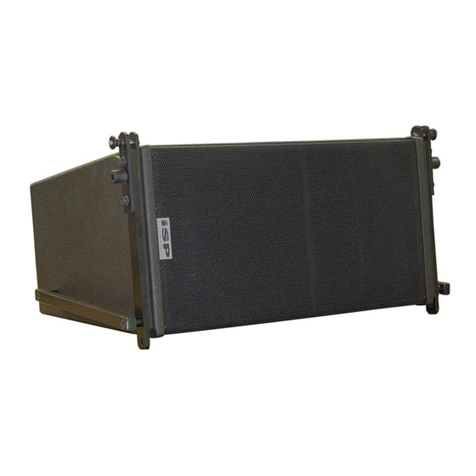
iSP Technologies VT110 User manual

1

2
IMPORTANT SAFETY INSTRUCTIONS
Please read the following very carefully before operating this unit
Read ALL instructions carefully before using this unit. Keep these instructions for future reference. Heed all warnings and follow all
instructions.
Do not use this unit near water, in the rain, or where there is moisture. If this warning is ignored a serious electrical shock or death may
occur.
Do not attempt to service this unit. No user serviceable parts inside. Refer servicing to qualified, ISP approved personnel. Servicing is
required when the unit is damaged in any way, such as power supply cord or plug is damaged, liquid has been spilled or objects have
fallen into the unit, the unit has been exposed to rain or moisture, does not operate normally, or has been dropped.
Do not block any ventilation openings on the unit. Do not install near heat sources such as radiators, heat registers, stoves, or other
apparatus that produces heat.
Do not defeat the grounding pin on the power plug. A grounding type plug has two blades and a third grounding prong. If the grounded
plug does not fit in your outlet, please consult an electrician for replacement of the outlet, which may be obsolete.
Care should be taken to avoid any foreign objects or liquid into this unit. Avoid exposure of this equipment to dripping or splashing and
ensure that no objects filled with liquid, such as vases, are placed on the equipment.
Only use accessories or attachments that are specified by the manufacturer.
Use only with the caster attachment, stand, connecting bracket, or table specified by the manufacturer, or sold as an accessory with the
unit. When a castor attachment is used, use caution when moving the cart/apparatus combination to avoid injury from tipping over.
To completely disconnect this unit from the AC mains, disconnect the power supply cord plug from the AC receptacle.
This active speaker system has internal power amplifier(s) and a heatsink located internally with cooling ports on the back of the unit for
airflow over the heatsink. Care should be taken to avoid placing this active speaker in a location where the airflow over the heatsink is
impeded and proper cooling of the internal amplifiers is not provided. Avoid placing this system close to other heat sources. The
external heatsink may reach high temperatures under normal use. Do not block the external heatsink with any other object. Make
certain there is proper ventilation for the external heatsink when in use.
Do not drive the unit into excessive heavy distortionfor an extended period of time to avoid premature speaker failure.
Failure to follow these instructions may void the warranty.
THIS UNIT CONTAINS POTENTALLY LETHAL VOLTAGES. TO PREVENT ELECTRIC SHOCK OR
HAZED, DO NOT REMOVE THE POWER AMPLIFIER MODULE, INPUT PANEL OR AC INPUT
PANEL. NO UER SERVICABLE PARTS INSIDE. REFER SERVICING TO QUALIFIED ISP
TECHNOLOGIES SERVICE PERSONNELL.
The lightning bolt triangle is used to alert the user to the risk of electric shock.
3
The exclamation point triangle is used to alert the user to important operating or maintenance
instructions.
Caution: Exposure to extremely high noise levels can
cause permanent hearing loss.
The VT110 speaker system is capable of producing in excess of 127db SPL at 1 meter.
Continued exposure to noise levels in excess of 90db may cause permanent hearing
loss. Below is a chart of the OSHA (Occupational Safety & Health Administration)
regulations for Occupational Noise Exposure. Please note: OSHA requires hearing
protection for any work environment when the sound levels exceed those shown in Table
G-16 when measured on the A scale of a standard sound level meter at slow response.

4
INTRODUCTION
Thank you for your purchase of the VT110 2-way active speaker system. The VT110
2-way design vastly reduces the problems inherent in typical 2-way designs, which
cause transient smearing and a lack of clarity. The VT110 is designed with extremely flat
response using high quality drivers delivering excellent performance in the critical mid-
range. High slope 24db per octave filters are used in the active crossover to allow a
lower frequency crossover point between the low band and high band of the system.
The VT110 also includes on board precision equalization correction to tune the response
for a ruler flat performance. The high-energy neodymium 10 inch woofer used has
higher sensitivity than typical woofers providing excellent SPL performance in a small
enclosure. The resonance of the woofer is also extremely low which means the low end
performance of the VT110 is excellent compared to other 10 inch cabinets. This results
in much better transient attack, lack of compression, and resolution of detail than any
other 2-way system. The VT110 also uses ISP Technologies new patented DAA
Dynamic Adaptive Amplifier Technology. The DAA power amplifier technology delivers
amazing performance and dynamic headroom with an adaptive rail class A/B topology.
This delivers sonic performance far above the common class D amplifiers used today but
with efficiency close to that of a class D amplifier for reduced heat and size. The new
DAA power amplifier technology also delivers lower power consumption off the AC line
than any other power amplifier currently available.
THERMAL CONSIDERATIONS
The ISP Technologies VT110 speaker system is capable of producing 1250 watts peak
power. This will generate heat that must be dissipated in order to maintain reliability and
insure the amplifier components stay within their operating temperature specs. To
accomplish this, the amplifier is mounted onto a heatsink that is vented on the front of
the cabinet. Airflow is forced through the fins via a fan that turns on when needed. It is
required that the vents remain free from any obstruction to allow proper ventilation to
occur.
In addition the amplifiers are thermally protected internally via a thermal switch, which
will attenuate the signal 40db if the power amplifier temperature ever exceeds 120C.
SUSPENDING LOUDSPEAKERS
Important Notice!!!
The information in this section has been gathered from engineering data and is for
informational purposes only. None of the information in this section should be used
without first obtaining competent advice with respect to applicability to a given
circumstance. None of the information presented herein is intended as a representation
of warranty on the part of ISP Technologies. Anyone making use of this information
assumes all liability arising from such use.

5
All information presented in this manual is based upon materials and practices that are
most common to The United States of America and may not directly apply to other
countries because of differing material dimensions, specs, and/or local regulations.
Users in outside countries should consult with appropriate engineering and regulatory
authorities for specific guidelines.
Correct use of all flyware is required for secure system suspension. Careful calculations
should always be performed to ensure that all components are used within their working
load limits before the cabinet suspended. Never exceed the maximum load ratings.
Before hanging any speaker system, always inspect all components for cracks,
deformations, corrosion, missing, loose or damaged parts that could reduce strength and
safety of the cabinet. Do not suspend the cabinet until the proper corrective action has
been taken.
ATTACHMENT TO STRUCTURES
A licensed professional engineer must approve the placement and method of attachment
to the structure prior to the installation of any overhead object. The following
performance standards should be provided to the professional engineer for design
purposes; Uniform building code as applicable, Municipal Building code as applicable
and Seismic Code as applicable.
INSPECTION and MAINTENANCE
Suspension systems are comprised of mechanical devices and, as such, they require
regular inspection and routine maintenance to insure proper function ability. Any
suspended ISP Technologies loudspeaker must be inspected for fatigue at least
annually. The inspection shall include a visual survey of all corners and load bearing
surfaces for signs of cracking, water damage, de-lamination, or any other condition that
may decrease the strength of the loudspeaker enclosure.
Flyware that is provided with or for any ISP Technologies loudspeakers must be
inspected for fatigue at least annually. The inspection shall include a visual survey of the
material for signs of corrosion, bending, or any other condition that may decrease the
strength of the fastener.
ISP Technologies is not responsible for the application of its products for any purpose or
the misuse of this information for any purpose. ISP is also not responsible for the abuse
of its products caused by avoiding compliance with inspection and maintenance
procedures.

6
REAR PANEL DESCRIPTION
1. VOLUME LEVEL
Select the level of volume output by starting with the knob turned all the way
counter-clockwise and turning it clockwise until desired volume is met.
2. XLR INPUT JACK
This female connector provides an input for balanced line level signal source
3. XLR OUTPUT JACK
This male connector provides a balanced loop through for connecting to
additional powered cabinets.
4. POWER SWITCH
Lets the user control the power of the amp by selecting if the speaker is off or
on.
5. NEUTRIK POWERCON CONNECTOR INPUT
This module provides a connection for the power cord.
6. FUSE REPLACEMENT
Twisting knob counter-clockwise can access the fuse.

7
SPECIFICATIONS
Configuration: 2-way system
LF Driver: 10 inch, neodymium, 600 W rms, vented
HF Driver: 1.75 inch v.c. compression, 60 W rms,
Polyester diaphragm, on CD horn
Coverage: 90 degree horizontal x 80 degree vertical
Construction: Baltic Birch Plywood. Powder coated steel grille
Finish: Black rubberized polyurethane, custom paint
available
Connector: XLR for audio input. Neutrik PowerCon for AC
power
Dimensions: 13”H x 21”W x 14.25”D
Weight: 53.5 lbs.
Amplifier: 625 LF + 100 HF watts RMS,
1250 LF + 200 HF watts PEAK
Built-in electronic crossover (4th order)
Power Required: 5 amps x 120 VAC
Freq. Range: 55 Hz to 19 KHz (-10 dB)
Freq. Response: 65 Hz to 16.5 KHz (+- 3 dB)
Axial Output Limit: 127dB (average), 133 dB (peak)

8
WARRANTY AND SERVICE
The Internal Circuitry is fully guaranteed to be free of defects under normal use and
service for a period of three years from the date of purchase. The Speakers and Cabinet
that are used in this product are fully guaranteed to be free of defects under normal use
and service for a period of three years.
Any damage resulting from the misuse or the failure to follow the precautions and
instructions will void the warranty.
In the event that the unit needs to be repaired. Please return the unit to ISP Technologies
directly. Simply repack the unit, send a copy of the original receipt, a note stating the
problem, and send it to:
ISP Technologies, LLC
5479 Perry Drive, Suite B
Waterford, MI 48329
Attn: Repair Dept.
All shipping charges must be fully prepaid.
ISP will not be responsible for any damages incurred in shipping of any unit. Any claim
will need to be settled with the shipping company.
The warranty will be voided if the serial number has been tampered with in any way.
The warranty card must also be filled out and returned in order to activate the warranty.
Should you have any questions for the repair department prior to returning the product
please call 1-(248)-673-7790
NOTE: This Product covered under the following patents: 9,402,128 / 9,641,133 /
9,853,602
NOTE: If it is determined that the power amp module has failed, it is possible for an ISP
certified service center to remove the module from the cabinet by removing the mounting
screws and disconnecting the speaker terminals and the transformer. The module may be
sent back to ISP separately. Please contact ISP for technical support to help determine if
the amplifier module may be defective.
ISP TECHNOLOGIES, LLC
5479 Perry Drive, Suite B
WATERFORD, MI. 48329
248-673-7790
FAX: 248-620-7696
www.isptechnologies.com
Table of contents
Other iSP Technologies Speakers manuals

iSP Technologies
iSP Technologies HDDS Series User manual

iSP Technologies
iSP Technologies HDDS SM800 User manual

iSP Technologies
iSP Technologies VMAX 1500 User manual

iSP Technologies
iSP Technologies HIGH DEFINITION LINE 2208Active Series User manual

iSP Technologies
iSP Technologies HDDS CS650 User manual

iSP Technologies
iSP Technologies ACTIVE 3112 User manual

iSP Technologies
iSP Technologies HDDS SM652-B User manual

iSP Technologies
iSP Technologies HDDS SM 650W User manual

iSP Technologies
iSP Technologies HDDS CS651 User manual

iSP Technologies
iSP Technologies VECTOR FS User manual