iSTEK 455C User manual

Desktop
Conductivity/TDS/Salinity/
Resistivity/Temp Meter
Model 455C
Instruction Manual
istek, Inc.

-1-
Conductivity/TDS/Salinity/Resistivity/Temp
Meter
TABLE OF CONTENTS
Chapter I Introduction .......................................................................................2
Chapter II Instrument Setup ...............................................................................3
Chapter III General Functions
Key Function ........................................................................................4
Display Description ..............................................................................5
Electrode Storage and Maintenance .....................................................6
Chapter IV Setup Functions ...........................................................................7~10
Clear Data(Memory) ............................................................................7
Chapter V Calibration and Measurement ................................................11~14
Chapter VI Data-Log .....................................................................................15~17
Chapter VII Remote Control ................................................................................18
Chapter VIII Troubleshooting and Error Descriptions .....................................19
Chapter IX Specifications ....................................................................................20
Chapter X Ordering Information .....................................................................21
Table of Contents

-2-
Conductivity/TDS/Salinity/Resistivity/Temp Meter
Chapter I. Introduction
istek's Desktop Conductivity/TDS/Salinity/Resistivity/Temp Meter(model 455C) is
operated by AC/DC(DC 9V) adaptor and is controlled by microprocessor for all
measurement needs.
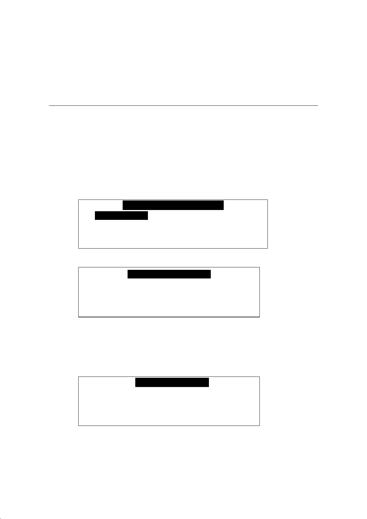
istek's Desktop Conductivity/Salinity/TEMP Meter(model 430C) features a graphic
LCD which simultaneously displays various functions along with measurement.
istek's Desktop Conductivity/TDS/Salinity/Resistivity/TEMP Meter(model 455C)
features to obtain a reliable data since its program is treated by setting in detail about
compensation factor for an accurate measurement.
istek's Desktop Conductivity/TDS/Salinity/Resistivity/Temp Meter(model 455C)
contains function which can know the last calibration status for Conductivity, e.g. the
last calibration Date/Time, Temperature and Standard solution etc.
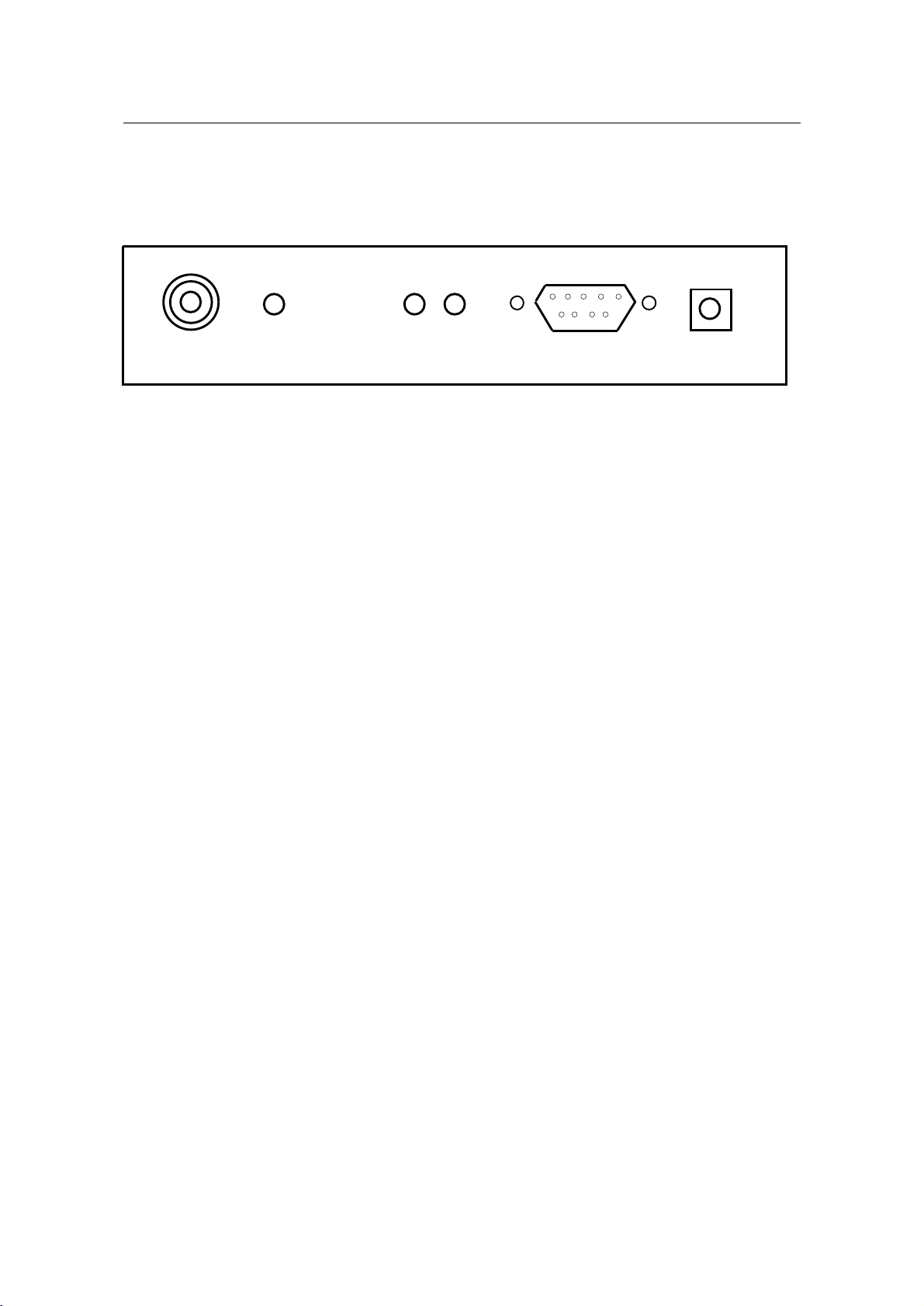
The model 455C is capable of storing up to 100 points in memory at once and storing
by control of the time interval of data-log automatically, and can be remotely
controlled via RS232C interface.
It is available to display unlimited number of each datalogging via Excel Software
with graph including GLP documentation by using DAPS.
The model 455C displays Conductivity(S, mS), TDS(mg/L), Salinity(ppt),
Resistivity (ohm, kohm, Mohm) and Temp(C).
Conductivity indicates conductivity of solution. (unit S/cm and mS/cm)
TDS indicates by converting the measured conductivity into concentration of
the total dissolved solid present solution from. (unit mg/L)
Salinity indicates by converting the measured conductivity into salinity of
solution. (unit ppt)
Resistivity indicates resistivity of solution at a current temperature.
Temperature Compensation(Temp)
For automatic temperaure compensation, a temperature probe supplied
by istek must be used.
Temperature is automatically compensated on the base of Tref adjusted
in Setup. Tref can be set with 25.0℃or 20.0℃for a basis.

-3-
Chapter I Introduction
Conductivity/TDS/Salinity/Resistivity/Temp
Meter
Chapter II. Instrument Setup
Real Panel
Power Source
Connect the supplied adaptor to the meter.
istek supplies AC/DC adaptor(DC 9V) adjusting to 220V.
Electrode Connection
Attach electrode by sliding the BNC connector onto the sensor input then push down
and turn clockwise to lock into position.
ATC Probe Connection
Attach the ATC probe to the ATC jack by sliding the connector straight on until
firmly in place.
Recorder Connection
When the recorder is used, connect the recorder to the meter. Output voltage is
-1999.9 ~ +1999.9 mV with impedance of 600 .
Printer and RS232C interface cable Connection
Insert printer and RS232C interface cable into the RS232C jack. Use interface cable
supplied by istek.
INPUT ATC RECORDER RS232C POWER

-4-
Chapter II Instrument Setup
Conductivity/TDS/Salinity/Resistivity/Temp Meter
Chapter III. General Functions
Key Function
Key Name Description
Power used to turn ON/OFF.
Reset used to initiate a system.
Mode used to change operating modes, such as conductivity, TDS,
salinity or resistivity.
Resolution used to change the resolution while measuring.
Ready/measure used to change condition of meter, i.e. measure or ready.
This is used for changing from ready to measure condition or
reversing.
Cal used to start or set calibration.
used to confirm the last calibration status.
Setup used to access the setup menu.
This is used for setting instrument parameters.
Can set Cell Constant, Temperature Coefficient, Temperature
Compensation, Date/Time and Data-Log.
Select used to move position of cursor.
used to measure conductivity without temperature compensation.
Enter used to set a selected data.
Memory used to store data in meter¡s memory while measuring.
In the ready condition, used to search the memorizeded data.
Out used to print data.
used to exit in Setup mode.
up() In setup and Data(Memory) mode, press to increase value.
down() In setup and Data(Memory) mode, press to decrease value.
Conductivity Meter Model 455C
Select
Power
Reset
Cal
Mode
Ready
Mea-
sure
Setup
Enter
Me-
mory
Out
Reso-
lution

-5-
Chapter III General Functions
Conductivity/TDS/Salinity/Resistivity/Temp
Meter
Display Description
The following display is specially specified.
Even some messages are not shown in the below display, describe together below.
Ready 96 / 11 / 12 11:15
0.00 uS/cm Tr. 25.0
2.1 %/C
Conductivity TEMP 25.0
C
Display Function
Conductivity indicates conductivity with range of 0 ~199,999 S/cm.
TDS indicates the amount of total dissolved solids presents in solution
(unit mg/L).
Salinity indicates salinity presents in solution at a current temperature. (unit
ppt)
Resistivity indicates resistivity of solution at a current temperature.
Temp(C) displays when a temperature probe is attached, and indicates
automatic temperature compensation.
Ready indicates that meter is in ready condition.
Measure indicates that meter is in measure condition.
96/11/12 11:15 indicates a current date and time.
Tr. 25.0 indicates that compensation of temperature is performed at
25.0 C.
Tr. 20.0 indicates that compensation of temperature is performed at
20.0 C.
------- indicates no temperature compensation.
2.10 %/℃indicates to compensate temperature with the temperature
coefficient, 2.10 %/C.
Error displays when it is not available to correctly measure because
something is wrong in the meter or buffer while calibrating or
measuring.

-6-
Chapter III General Functions
Conductivity/TDS/Salinity/Resistivity/Temp
Meter
Electrode Storage & Maintenance
Conductivity Cell Storage
A dirty cell will contaminate the solution and cause conductivity to change. It is best
to store cells that are immersed in deionized water. Provided the cell has been stored in
condition of drying, should be soaked in distilled water for five to ten minutes before
using to keep electrode wet.
Conductivity Cell Maintenance (Cell Cleaning)
Glease, oil, fingerprints, and other contaminants on the sensing elements can cause
erroneous measurements and sporadic responses.
If it takes long time to response or a stable data isn't obtained, can be often restored to
normal performance by using the following procedures;
Clean cells with detergent and/or dilute nitric acid(1%) by dipping or filling the cell
with cleaning solution and agitating for two or three minutes. Other diluted acids(e.g.
sulfuric, hydrochloric, chromic) may be used for cleaning except for aqua regia. When
a stronger cleaning solution is required, try concentrated hydrochloric acid mixed into
50% isopropanol.

-7-
Chapter III General Functions
Conductivity/TDS/Salinity/Resistivity/Temp
Meter
Chapter IV. Setup Functions
The setup menu is used to identify and change instrument parameters.
Temperature Setting
If temperature on display differs from a real temperature, set a real temperature
according to the following procedure.
Press Setup and then the display is shown as follows.
<< COND SETUP >>
1.Cell/Tref/TC
2.Date/Time
3.Data-Log
4.Exit
Press Mode key.
<< TEMP SETUP >>
21.3℃
Set temperature by using or key and exit by pressing Out key.
Clear data(Memory)
If clearing the stored data, press Mode key to enter Salinity mode. The display is
shown as follows. And then press Enter to clear. Therefore all data, which set at setup,
are changed to a basic value.
<< CLEAR >>
Memory Clear ?
(Yes = Enter) (No = Out)
(1) Conductivity Mode
In the conductivity ready condition press Setup key to enter setup and then the
message is shown as follows.

-8-
<< COND SETUP >>
1.Cell/Tref/TC
2.Date/Time
3.Data-Log
4.Exit
Chapter IV Setup Functions
Conductivity/TDS/Salinity/Resistivity/Temp
Meter
The selected menu shows an emphasized black color in turn with pressing Select key
and the condition of each item is set with pressing Enter key.
After finishing setup, press Out key or select a displayed Exit to exit.
Cell/Tref/TC
In the initial display of Conductivity Setup, after selecting 1.Cell/Tref/TC by using
Select key, press Enter key and then the display is shown as follows.
<< Cell/Tref/TC >>
1. Cell 1.0
2. Tref 25.0
3. TC 2.10
4. Exit
1) Cell
1. Cell has function to set cell constant. For conductivity measurement of a solution,
can accurately measure by adjusting cell constant. Cell constants consist of 0.01, 0.1,
1.0, 10 and 100, and set by using or key.
2) Tref
2. Tref has function to set compensation temperature(25.0 C or 20.0 C).
<< Cell/Tref/TC >>
1. Cell 1.0
2. Tref 25.0
3. TC 2.10
4. Exit
Press or key to change 25.0 or 20.0. The conductivity of a solution exhibits at
25.0C or 20.0 C.
3) TC
3. TC is used to set temperature coefficient. The conductivity of solution with a
specific electrolyte concentration will change in accordance with the change of
temperature. Each conductive ion has a different temperature coefficient.
All istek's meters allow adjusting coefficient for the advanced performance.
<< Cell/Tref/TC >>
1. Cell 1.0
2. Tref 25.0
3. TC 2.10
4. Exit
Press or key until the desired value is displayed.

-9-
The following table is a typical temperature coefficients(percentage of change of
conductivity per C).
Solution %/ C
Ultrapure Water 4.55
Salt(NaCl) 2.12
5% NaOH 1.72
Dilute Ammonia 1.88
Chapter IV Setup Functions
Conductivity/TDS/Salinity/Resistivity/Temp
Meter
Solution %/ C
10% HCl 1.32
5% Sulfuric Acid 0.96
98% Sulfuric Acid 2.84
4) Exit
If finishing setup or exiting setup in the middle of setting, select Exit and press Enter
key. Out key has the same function.
Date/Time
In the initial display of setup, after selecting 2. Date/Time by using Select key, press
Enter key. Select data(year, month, day and time etc.) with Select key and adjust data
by using or key.
<< DATE/TIME SET >>
< Current Time >
96 / 11 / 26 13 : 36 : 36 [Exit]
If finishing setup, press Out key or select a displayed Exit to exit Date/Time setup.
Data-Log
In the initial display of setup, After selecting 3. Data-Log by using Select key, press
Enter key. And then the display is shown as follows. Select data by using Select key.
<< DATA LOGGING >>
1. Destination : Memory
2. Time Interval : 0 min
3. Exit
1) 1.Destination is a place to store memory type, such as memory, printer or Excel etc.,
by using or key.
If pressing Enter key in 1.Destination, display is shown as follows.
<< RS232C SETUP >>

-10-
Baud Data Stop Parity
9600 8 1 No
[Exit]
Select communication data by using select key, and set Baudrate, Data Bit, Stop
Bit and Parity Bit by using or key.
Baud : adjust communication rate between computer and meter by using or
key.
Data : adjust Data Bit between computer and meter by using or key.
Stop : adjust Stop Bit between computer and meter by using or key.
Parity : adjust Parity Bit between computer and meter by using or key.
Chapter IV Setup Functions
Conductivity/TDS/Salinity/Resistivity/Temp
Meter
If finishing setup press Out key or a displayed Exit to exit RS232C setup.
2) Time Interval
In order to store data to any Destination with certain, select a desired time
interval(minutes or seconds) by using or key.
<< DATA LOGGING >>
1. Destination : Memory
2. Time Interval : 0 min
3. Exit
Unit of time interval, such as minutes and seconds, is changed by pressing Enter
key.
Adjust time interval by using or key.
<< DATA LOGGING >>
1. Destination : Memory
2. Time Interval : 0 sec
3. Exit
Time interval ranges from 1 second to 23 hours 59 minutes 59 seconds.
3) Exit
If finishing setup, press either Out key or a displayed Exit key to exit Data-Log
setup.
Exit
If finishing setup or exiting setup in the middle of setting, select a displayed Exit and
press Enter key. Out key has the same function as Exit key.
(2) TDS Mode
In the TDS ready condition if pressing Setup key, the display is shown as follows.

-11-
TDS factor adjusts by using or key and is basically adjusted to 0.7.
<< TDS FACTOR INPUT >>
0.70
If finishing setup, press either Out key to exit setup.
Chapter IV Setup Functions
Conductivity/TDS/Salinity/Resistivity/Temp
Meter
Chapter V. Calibration and Measurement
The basic condition is as follows.
¡Cell Constant (Cell) : 1.0
¡Compensation Temperature (Tref) : 25.0
¡Temperature Coefficient(TC) : 2.10 %/C
¡Data-Log : memory
This meter contains function to confirm the last calibration status of conductivity.
(1) Conductivity Calibration Status
In conductivity ready condition press Setup key and Cal key or in measurement
condition press Cal key to enter ¡Cond Calibration Status¡.
<< Cond Calibration Status>>
1. Date/Time : 98/03/26 17:30
2. Temp : 18.0
3. Tref : 25.0
4. Standard : 146.9 uS/cm
Confirm Date/Time, temperature(Temp) and compensation temperature(Tref) and
standard solution used for the last calibration. If pressing Out key, return to an initial
display.
If clearing data, can¡t confirm the last Calibration Status, and the display is shown as
follows.
<< Cond Calibration Status>>

-12-
1. Date/Time : 00/00/00 00:00
2. Temp : 0.0
3. Tref : 0.0
4. Standard :
No Data
Chapter V Calibration & Measurement
Conductivity/TDS/Salinity/Resistivity/Temp
Meter
(2) Preparation
Connect meter with cell and ATC jack.
Prepare a required buffer for measurement and magnetic stirrer.
Clearly rinse cell with the distilled water and blot dry.
(3) Calibration
In conductivity ready condition, press Cal key to enter calibration mode.
The display is shown as follows, and select standard solution by using Select key.
[Cal] Ready 146.9 uS
1413 uS
6.67 mS
0.00 uS/cm 12.89 mS
TEMP : 18.0 Tr : 25.0 111.9 mS
Put cell into the selected standard solution and press Measure key.
Put cell into standard solution and press Measure key.
[Cal] Measure 146.9 uS
1413 uS
6.67 mS
143.6uS/cm 12.89 mS
TEMP : 18.0 Tr : 25.0 111.9 mS
After the reading is stable, press Cal key and then Cal-OK message is displayed and
returns to an initial mode.
[Cal] Cal-OK 146.9 uS
146.9
uS/cm
1413 uS

-13-
6.67 mS
12.89 mS
TEMP : 18.0 Tr : 25.0 111.9 mS
If using standard solution that not showing on screen, adjust conductivity by using
or key .
[Cal] Ready 158.7 uS
1413 uS
6.67 mS
0.00 uS/cm 12.89 mS
TEMP:18.0 Tr:25.0 111.9 mS
Chapter V Calibration & Measurement
Conductivity/TDS/Salinity/Resistivity/Temp
Meter
The following table is shown correlation conductivity with concentration of KCl
solution.
KCl solution(M)
Conductivity
0.001 146.9 S/cm
0.01 1413.0 S/cm
0.05 6.67 mS/cm
0.1 12.89 mS/cm
1 111.9 mS/cm
(4) Measurement
1) Conductivity Measurement
In the calibration, TC(i.e. Temperature Compensation Coefficient) is automatically
selected by standard solutions and measuring temperature. KCl solution have a lower
temperature coefficient (app. 1.9%/
C) of conductivity than typical potable water.
Sodium chloride(NaCl) has a temperature coefficient (2.12%/
C) that closely
approximates that found in most waters from wells and surface sources.
Press Measure key to measure the conductivity of solution. The display is shown as
follows. Measure 96 / 11 / 12 11:15
1413uS/cm Tr. 25.0
2.10 %/C℃
Conductivity TEMP 18.0 C
After the reading is stable, store or record it. If measuring conductivity without
compensation of temperature, press Select key to measure conductivity at measuring
temperature without compensation of temperature.

-14-
Measure 96 / 11 / 12 11:15
1215uS/cm
-----------
Conductivity TEMP 18.0 C
2) TDS Measurement
The preparation for TDS is the same as for conductivity.
Press Mode key to enter TDS mode.
Press Measure key to measure TDS of solution.
Measure 96 / 11 / 12 11:15
798.4 mg/L Tr. 25.0
2.10 %/C
TDS TEMP 18.0 C
Chapter V Calibration & Measurement
Conductivity/TDS/Salinity/Resistivity/Temp Meter
While measuring conductivity, can measure TDS by pressing Mode key.
3) Salinity Measurement
The preparation for salinity is the same as for conductivity.
Press Mode key to change salinity mode.
Press Measure key to measure salinity of solution.
Measure 96 / 11 / 12 11:15
0.7ppt
Salinity TEMP 18.0 C
While measuring conductivity or TDS, can measure salinity by pressing Mode key
4) Resistivity Measurement
The preparation for resistivity is the same as for conductivity.
Press Mode key to change resistivity mode.
Press Measure key to measure resistivity of solution.
Measure 96 / 11 / 12 11:15
12.5kohm
Resistivity TEMP 18.0 C
While measuring conductivity, TDS or salinity, can measure resistivity by pressing
Mode key

-15-
Chapter V Calibration & Measurement
Conductivity/TDS/Salinity/Resistivity/Temp Meter
Chapter VI. Data -Log
Model 455C can transmit information to printer or computer via RS232 interface.
Data-Log consists of memory, excel and printer etc.
(1) Memory Data - Log
The basic condition of Data-Log is set as follows.
<< DATA LOGGING >>
1. Destination : Memory
2. Time Interval : 0 min
3. Exit
The measured data is stored in meter by pressing Memory key manually.
If the condition of Data-Log is set as follows(refer to Setup), the measured data is
automatically stored with time interval of one minute in meter.
<< DATA LOGGING >>
1. Destination : Memory
2. Time Interval : 1 min
3. Exit
Unit of time interval, such as minutes and seconds, is changed by pressing Enter key.

-16-
<< DATA LOGGING >>
1. Destination : Memory
2. Time Interval : 0 sec
3. Exit
Up to 100 points are stored in memory at once.
[ DATA MODE ]
No. 3 96 / 11 / 26 11 : 15
Conductivity : 1215 uS
Tref : 25.0
If setting Destination as ¡None¡, data isn't stored. If needing to print the stored data in
meter, it is available to output by using printer supplied by istek. In ready or measure
condition, enter Data(Memory) Mode by Memory key, search the stored data in meter
by using Select key and press Out key to print data.
Chapter VI Data-Log
Conductivity/TDS/Salinity/Resistivity/Temp
Meter
The following figure is an example to print.
[DATA MODE]
Number : 3
Date & Time [ 96/11/26 11:15 ]
conductivity : 1215 S
Tref : 25.0 C
(3) Printer Data-Log
Connect meter to printer via RS232C interface cable supplied by istek.
If condition of Data-Log is set as follows, the measured data is automatically printed
every one minute.
[B] << DATA LOGGING >>
1. Destination : Printer
2. Time Interval : 1 min
3. Exit
In case of the direct output by printer, must use printer supplied by istek.
The following figure is an example to print.
[DATA MODE] Number : 3
Date & Time [ 96/11/26 11:15 ]
Conductivity : 1215 S

-17-
Tref : 25.0C
(3) Excel Data-Log
Connect meter to PC via RS232C interface cable supplied by istek.
It is available to store data in PC while measuring by pressing Memory key regardless
of time. If the condition of Data-Log is set as follows, the measured data is
automatically stored in PC with excel form every one minute.
<< DATA LOGGING >>
1. Destination : Excel
2. Time Interval : 1 min
3. Exit
If DAPS(Data Acquisition and Processing Software) is performed, the display of
monitor as follows. The installation method of DAPS refer to DAPS manual.
Chapter VI Data-Log
Conductivity/TDS/Salinity/Resistivity/Temp
Meter

-18-
Chapter VI Data-Log
Conductivity/TDS/Salinity/Resistivity/Temp Meter
Chapter VII. Remote Control
The meter can be remotely controlled by PC.
After connecting your meter to PC by RS232C interface cable and performing
communication program of computer, if pressing Enter key of PC keyboard, remotely
controlled and key button of meter doesn't work.
Ready 96 / 11 / 12 11:15
0.0 uS/cm Tr. 25.0
2.10 %/C
Remote Control TEMP 18.0 C
When Remote control is started, message ¡ Conductivity Remote Control Mode¡ is
displayed on the monitor of computer.
ISTEK>Conductivity Remote Control Mode
ISTEK>
If inputting help while performing communication program, the remote control
commands are displayed on the monitor of computer.
ISTEK>help
The following messages are the remote control commands.

-19-
: ----------- Command List -------------:
1. exit : Exit Remote Control
2. cond : Read Conductivity
3. tds : Read TDS
4. sal : Read Salinity
5. r : Read Resistivity.
6. temp : Read Reference Temperature
7. data : Read the stored data in meter
8. help : Command Help Message
The following message is to read a conductivity.
ISTEK>cond
conductivity : 1413 S
In case of reading the data stored in meter if inputting data, message "Data Reading
No :" is displayed
ISTEK>Remote Control Mode
ISTEK>data
Data Reading No:
If inputting Data Number the data stored in meter is displayed as follows. This is also
used by storing in "screen capture" or recording.
[DATA MODE] Number : 3
Date & Time : [ 96/11/26 11:15 ]
conductivity : 1413 S
Tref : 25.0 'C
Chapter VII Remote Control
Conductivity/TDS/Salinity/Resistivity/Temp
Meter
Chapter VIII.
Troubleshooting & Error Description
Symptom Possible cause Remedy
Erratic reading Faulty connection between
meter and sensor Tighten connection
Broken cable Replace cable
Air trapped in conductivity
Cell
Agitate cell up and down
to expel trapped air
Change of water temperature
Measure in situ
Broken conductivity cell Replace cell
Table of contents
Other iSTEK Measuring Instrument manuals