iSTEK DO-350L User manual

Instruction Manual
Model DO-350L (DO/O2/AIR/ pO2/TEMP
website: www.istek.co.kr
E-mail: istek@istek.co.kr
istek, Inc.

2
Chapter I. Instruction
This desktop Meter (Model DO-350L , the latest- model is operated by AC/DC adaptor (DC
12V , a high performance model controlled by microprocessor for all measurement needs.
The model DO-350L is capable of storing up-to 500 points in its memory box and storing by
control of the time interval of data-log automatically. And also, by using RS232C cable, it can
be remotely controlled and transmitted the measured information to the printer or computer
by 1 second interval.
DO-350L (DO/O2/AIR/ pO2/TEMP
If a pH value is stable, a world “Stable" is displaying on the screen, therefore a user can
measure the sample more accurately. And it features Auto/Manual calibration and displays
DO
(mg/l , O
2
, pO
2
, Air
and temp (℃
DO Displays concentration of dissolved oxygen with range of 0.00 to 19.99 mg/L.
O2 Indicates percentage of oxygen as compared to the amount of oxygen presents in
the air.
Air Indicates percentage of DO concentration.
Alt Indicates Altitude by meter. It is shown in Setup mode.
ATC Indicates Automatic Temp Compensation, a temperature probe supplied by istek
must be used. Temperature Compensation is automatically performed indicates
present temp and in case of it is unconnected with the meter, it displays 25℃
℃℃
℃.

3
Chapter II. General Functions
2.1 Instrument Setup
Rear Panel of DO-350L
Power Source
Connect the supplied AC/DC adaptor to Power Jack of the meter.
istek supplies AC/DC adaptor(DC 12V) adj sting to 220V.
With b ilt-in Printer: 12V, 3A
Witho t b ilt-in Printer: 12V, 1A
This meter can be used in free voltages and if you would like to use this to 110V, just use a
proper connector for inserting a users plug.
Sensors and ATC probe Connecting
We recommend using electrodes which were provided by istek, Inc. for optimum working.
Put it into BNC Jack and turn it clockwise to lock into position. And Attached ATC probe to the
ATC jack by sliding the connector straight on until firmly in place.
RS232C interface cable Connecting
Using this RS232C Interface cable, it is available to connect the meter with Printer (Or
Computer and user can edit or print the data easily. For further information, please refer the
Chapter 4 <Data –Log> Part
RS232C
POWER
CH 1

4
2.2 Display Description
This is an initial display of DO-350L.
Initial display of ▣
▣▣
▣ DO-350L
Display Function
--------------------------------------------------------------------------------
DO
Indicates Concentration of Oxygen presents in the water.
O2
Indicates Percentage of Oxygen which is based Amount of oxygen
presents in the air.
Air
Indicates Percentage of Dissorlved Oxygen or O
2
Concentration.
Set p Indicates to change each selected value per measuring Item
Cal Indicates that meter is in calibration condition
Memory Indicates for confirming each saved data per Item
Help Indicates to check interior simplicity manual which is saved in instruments
Message When you select each Menu or item, this message is appeared
05/08/24 Indicate of using data of the instrument
15:00:32 Indicate of using time of the instrument

5
2.3 Electrode Structure
DO Polarographic Probe Storage & Maintenance
1. Electrode Body
2. Stainless Steel Ring
3. Screw
4. Sensor; position of response to oxygen
5. Membrane Cover; containing with the filling Solution
6. Membrane Protector& Holder
7. Membrane
Probe Storage and Maintenance
- DO Probe Storage
For longer storage, cover the membrane tip with a cap originally supplied by istek.
- DO Probe Maintenance (Probe Cleaning
If it takes long time to response or a stable data is not obtained, check
membrane. If air bubble is occurred on membrane, remove air bubble.
Check membrane for damage (i.e. holes and leak, etc. . If membrane gets damage, replace
membrane.

6
Chapter III. Setup Functions
3.1 Setup in DO Mode
3.1.1 Setup in DO Mode
From the Initial display, select <DO> Item by pressing Move Key.
After selecting <DO> and press Memory/O t Key, then below (right one is displayed. From
the display, move to <Setup> by using Move Key. Each single item can be selected by
pressing Enter Key.
3.5.1.1 Setting Salinity and Altitude in Setup menu.
In DO Setup, press Enter Key
Enter KeyEnter Key
Enter Key to select Salinity and Altitude
Select DO by using Move Key and Enter Key. After selecting DO then, press Memory/O t
Key to enter DO Mode (Left picture . User can move easily to Main Menu by pressing Move
Key. Press Enter Key from Setup mode to enter Setup Mode.
Setting Salinity and Altitude in Setup menu.
In Setup Mode, press Enter Key to select Salinity and Altitude
User input data by pressing Up/Down Key.
(1 Salinity: 0 to 70 ppt. It changes 0.1 for every one press.
(2 Altitude: 0 to 4,000m. It changes 50m for every one press.
- Salinity Mode

7
- Altit de Mode
Setting Temp in Setup menu.
In DO Setup Mode, press Move Key to move to Temp and press Enter Key. The following
screen will be shown.
ATC Probe is connected with Meter, right display is displayed directly.
And user is able to put temp manually also. If there are quite difference between temp in the
Meter and Real Temp, user set correct time by the direction appeared the bottom of screen.
Setting Common in Setup
From this <Setup>, move to <Common> mode by pressing Move key.
After pressing Enter Key, then below is displayed.
By itemize, it is available to input or change a value following as the message
(1 Time: Available to change <temp> and <date>, which is displayed on the LCD
(2 RS232: Available to input or change a time Interval of <Data-Logging>.

8
3.1.2 Calibration in DO Mode
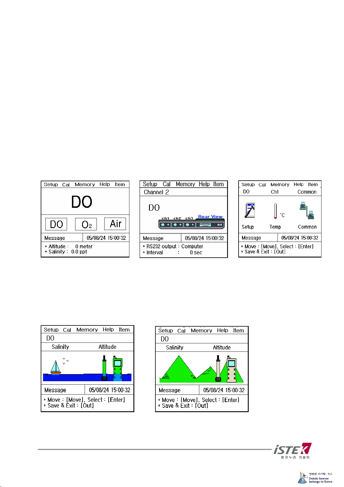
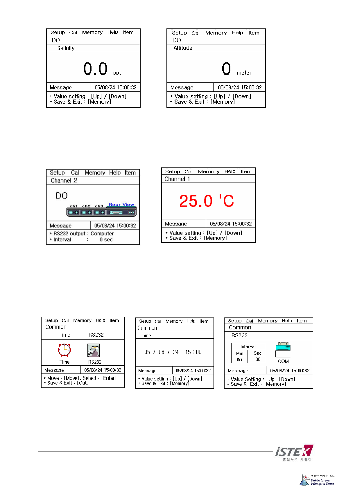
※ Salinity, Altitude and temp are the factor what is influence to dissolved oxygen. So, user can
set this factor in Setup mode and after setting, the values are displayed at bottom of LCD.
※ Because of using polarographic Electrode, after power on and user should wait for 20 min
for stabilizing.
※ Rinse DO sensor with distilled water carefully and remove moisture and put it in the air.
Preparation
Connect DO sensor and ATC probe with Meter (Back side
Clearly rinse probe with distilled water and blot dry with tissue.
Prepare solution for calibrating and magnetic stirrer.
It takes 20 minutes to polarize probe because of using polarographic sensor.
User stirs solution by using magnetic stirrer constantly.
DO sensor should be kept saturate solution with oxygen by the bubbling equipment at least
1~2 hours for accurate calibration.
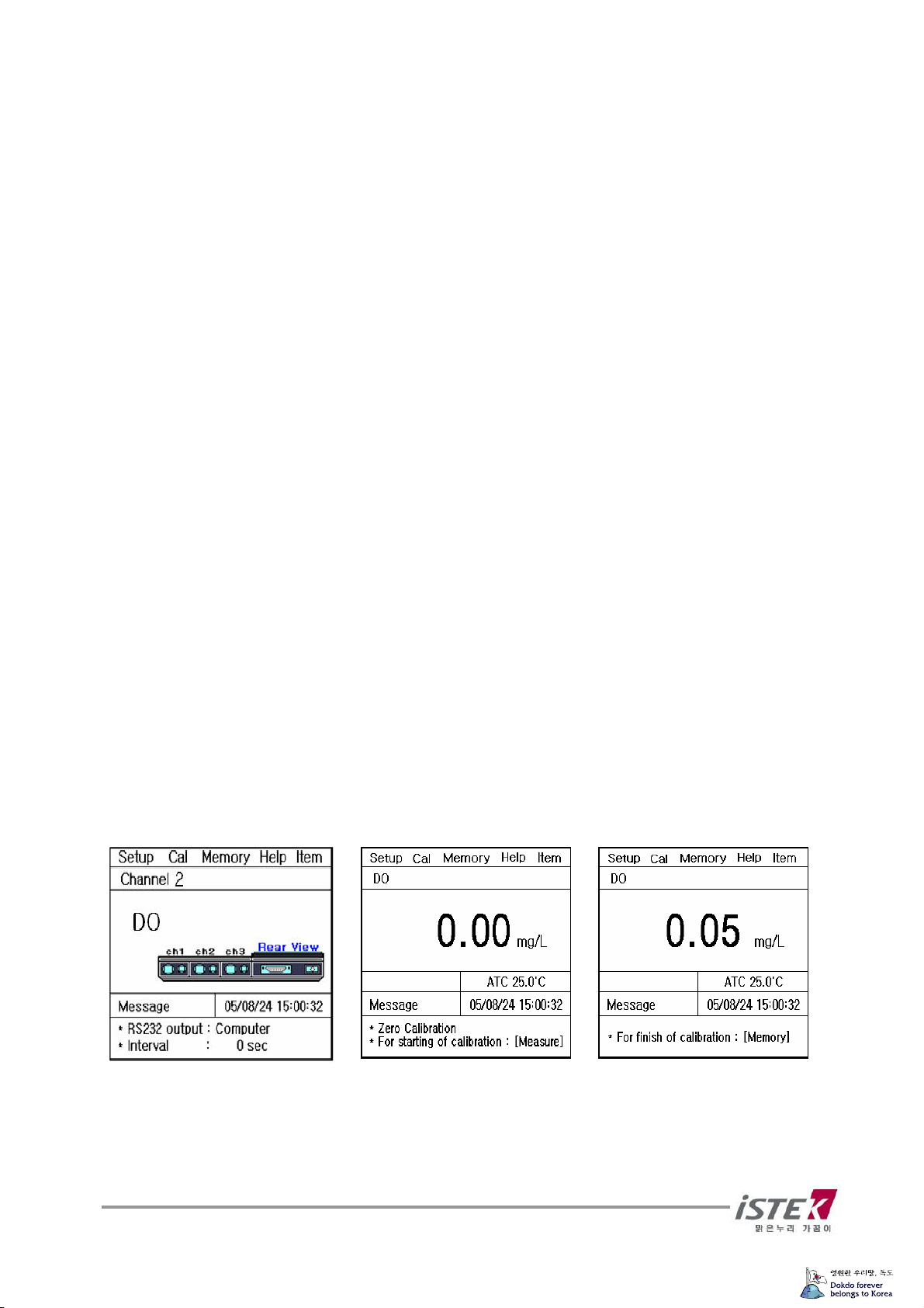
Zero Calibration
There are two ways of Zero calibration.
User can enter cal Mode by using Move Key. And press Enter key.
1 In case of calibration with solution not containing DO, add excess sodium sulfite, Na2SO3,
and a trace of cobalt chloride, CoCl2, to bring DO to zero. Put probe into this solution.
2 In case of calibration without solution, remove probe from Input and press Meas re Key.
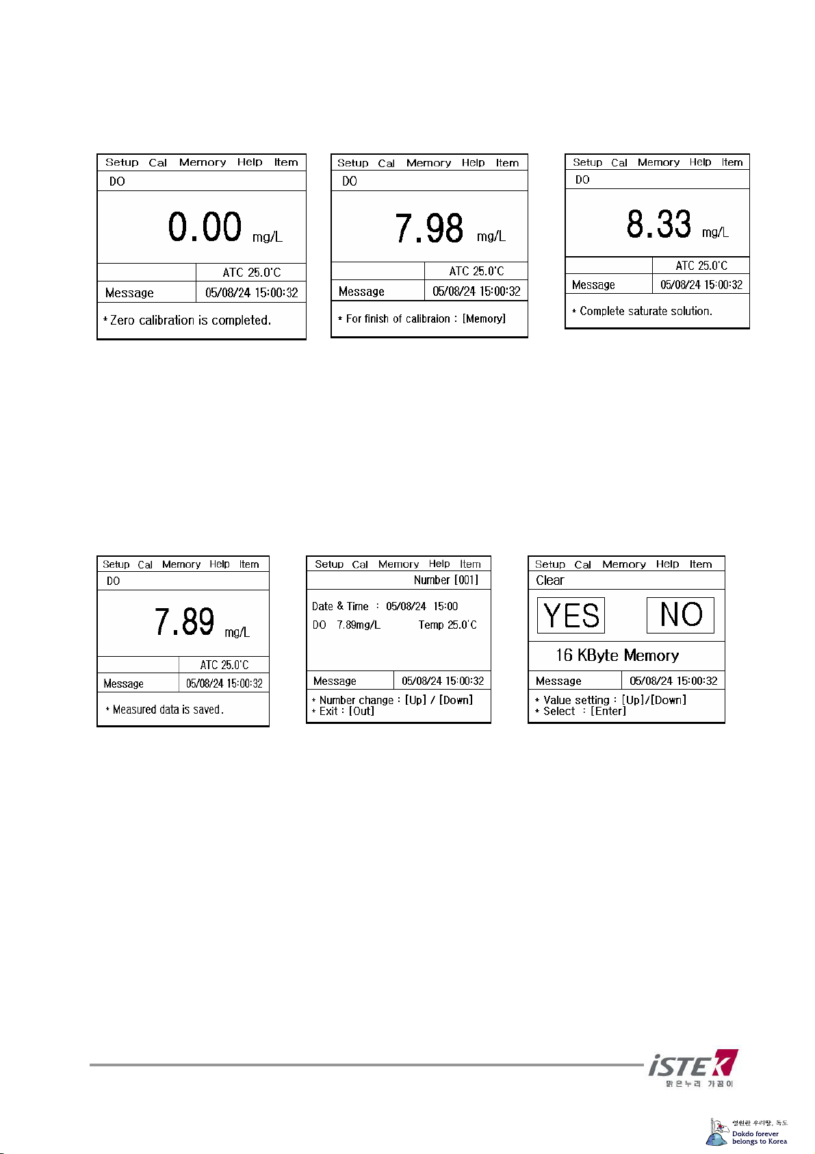
If the reading is stable, press Cal Key, and then Cal-OK message is displayed in the upper
field and set automatically.
Put saturated solution into BOD bottle and cap to minimize the exposure in the air.
In initial DO display, press Move Key to change to Cal and press Enter Key.
Put probe into a zero solution and press Meas re Key.
If data stables, press Memory/O t Key to finish calibration using zero solution.

9
After calibration, the following display will be shown and it automatically changes into second
calibration; saturated calibration. Put probe into a saturated solution and press Meas re Key.
If data stables, press Memory/O t Key to finish calibration.
`
After finishing calibration, it automatically moves to DO initial display and calibrated date and
method will be shown at the screen.
3.1.3 Memorizing in DO Mode.
While measuring DO, press Memory/O t Key and data will be stocked with a following
display. Searching for stored data, press Move Key in DO initial display to move to Memory.
Press Enter Key and moves to stocked data mode.
It is indicated <Measuring date>, <Time> and <Saved data> besides this, user can search a
former date which was saved. If user would like to clear whole memories, press Memory/o t
Key to move Memory Clear Display After memory clear, whole data and selected values in
Setup Mode will be deleted completely. In case of the instrument can’t sense a connected
electrode or wrong time settled or wrong data memories are saved, User can try <Memory
Clear>.

10
3.1.4 Help in DO mode
From DO initial display, press Move Key to move Help Mode
User can select proper language by using Move Key, and press Enter Key to see the Help
Manu in detail.
3.1.5 Measuring pO2.
While measuring DO, press Mode Key for changing pO2 and DO alternately.
Following display is for pO2.

11
3.2 Setting O2
3.2.1 Setup in O2 Mode
From the Initial display, select O2 Item by pressing Move Key. After selecting O2 and press
Memory/O t Key, then below (right one is displayed.
From the display, move to Setup by using Move Key. Each single item can be selected by
pressing Enter Key.
Setting Altitude in setup menu
In O2 Setup, press Enter Key and the following display will be shown.
You can change altitude by pressing Up/Down Key 50m per a hit.
Setting Temp menu in Setup.
In O2 DO Setup display, press Move Key to move to Temp and press Enter Key. The following
screen will be shown.

12
If the ATC probe is disconnected with the meter, left display with direction “Connect Temp
Sensor “is shown. And the ATC is connected with it, you can go to right display directly.
And user is able to put temp manually. If there are quite difference between temp in the Meter
and Real Temp, you can set correct time by the direction appear the bottom of screen.
Setting Common in Setup menu
In O2 Setup display, press Move Key to move to Common and press Enter Key. The following
screen will be shown.
By itemize, it is available to input or change a value following as the message from the bottom
of LCD. You may refer to DO setup for the details.
3.2.2 Calibration in O2 Mode
In O2 initial display, press Move Key to move to Cal and press Enter Key. Then you can see
the following display.
If the data stables, press Memory/O t Key to finish calibration.
After finishing calibration, it automatically moves to O2 initial display and calibrated date and
method will be shown at the screen.

13
3.2.3 Memorizing in O2 Mode
While measuring O2, press Memory/O t Key and measuring data will be stocked.
If you would like to find the measuring data which you’ve saved, in the initial display of O2,
move to Memory by pressing Move Key twice. And press Enter Key to move memories.
You may refer to [DO setup] part for the details.
3.2.4 Help in O2 Mode.
From initial display of O2, press Move Key three times to move <Help>.
After that, press Enter Key then, a display is shown as the DO Mode.

14
3.3 Setting AIR
3.3.1 Setup in AIR Mode.
From the Initial display, select Air Item by pressing Move Key. After selecting Air and press
Memory/Out Key, then below (right one is displayed.
From the display, move to <Setup> by using Move Key. Each single item can be selected by
pressing Enter Key. You may refer to DO setup for the details.
Setting Altitude in Setup menu.
In AIR Setup, press Enter Key and following display will be shown.
Yu can change altitude by pressing Up/Down Key 50m per a hit.
Setting Temp in setup menu.
From this Setup, move to Temp mode by pressing Move Key.
After pressing Enter Key, then below is displayed.

15
If the ATC probe is disconnected with the meter, left display with direction “Connect Temp
Sensor “is shown. And the ATC is connected with it, you can go to right display directly.
And user is able to put temp manually. If there are quite difference between temp in the Meter
and Real Temp, you can set correct time by the direction appear the bottom of screen.
Setting Common in Setup menu.
From this <Setup>, move to <Common> mode by pressing Move key.
After pressing Enter Key, then below is displayed.
By itemize, it is available to input or change a value following as the message from the bottom
of LCD. You may refer to DO setup for the details.
3.3.2 Calibration in AIR Mode.
From the Initial display, select Air Item by pressing Move Key. After selecting Air and press
Cal Key, then below is displayed
If the data stables, press Memory/O t Key and finish setup.
After finishing calibration, it automatically moves to Air initial display and calibrated date and
method will be shown at the screen.

16
3.3.3 Memory in AIR Mode.
While measuring Air, press Memory/O t Key for saving the data.
If you would like to find the measuring data which you’ve saved, in the initial display of O2,
move to <Memory> by pressing Move Key twice. And press Enter Key to move memories
It is available to be indicated measured data, time and saved-data. Beside this, you also can
search the former dates which were saved by using Up/Down Key. And if you would like to
<Memory Clear>, press Memory/o t Key to move Memory Clear Display. After memory
clear, whole data and selected val es in Set p will be deleted completely. In case of
the instrument can’t sense a connected electrode or wrong time settled or wrong data
memories are saved, you can try <Memory Clear>

17
Chapter IV. Data-Logging
4.1 Data-logging in Memory
The measured data is stored by pressing Memory Key manually.
If user would like to print the data which is stored in meter, search data stored in instrument
by using Up/down Key.
<Data –log in DO Mode>
4.2 Data-Logging to Printer & Computer
From each Mode, press [Setup Menu] -> [Common Menu] -> [RS232 Menu]
And below is displayed.
‘
By using Move Key, user can move to section of Interval and select ‘Printer’ or ‘Com(PC ’.
When user selected each condition, then the date will be printed at the appointed intervals.
Also it is printed whenever user press Print Key regardless of setting conditions.
When user wants to receive the data with regular interval in computer, there are 2 different
ways. At first, user gets it via Hyper Terminal at the appointed intervals. Second is via SDIS
software which is provided by istek, Inc. (Optional , user can receive and edit the data in MS
Excel program easily. And also make a relative graph with the data or other many functions it
has.

18
Chapter V. Troubleshooting & Error Description
MALFUNCTION POSSIBLE CAUSE REMEDY
Press Power key.
No power to meter Check that battery is
inserted correctly and
polarity signs match.
Out of range reading
or unstable reading
Probe failure
Clearly rinse electrode
and blot dry.
If air bubble is
Occurred on
membrane, remove
air bubble.
Check membrane for
damage(i.e. holes
and leak, etc.
If membrane gets
damage, replace
Membrane.
If the cause is uncertain, clear memory (data to eliminate all data.
Refer to Clear Memory (data of Setup Functions.
* When using Ion Selective Electrodes, refer to ISE manual.
※ If the problem persists, please contact istek, Inc Product Service Department.

19
Chapter VI. Specifications
Model DO-350L
DO
Range
Resol tion
Relative Acc racy
0.00 to 19.99 mg/L
0.01/0.1
±0.5%
O2
Range
Resol tion
Relative Acc racy
0.0 to 60.0%
0.1%
±1 digit
Air Sat ration
(%)
Range
Resol tion
Relative Acc racy
0.0 to 1999.9%
0.1%
±1 digit
Temperat re
Range
Resol tion
Relative Acc racy
-10 to 60℃
0.1℃
±0.4℃
Salinity Correction 0 to 70ppt
Altit de Correction 0 to 4000m
Data-Logging 500 Point
Temperat re Compensation Auto
Calibration Auto
Inp t One BNC, One ATC, Power, RS232C
O tp t RS232C (Computer/Printer
Power Adaptor

20
Chapter VII. Ordering Information
※ Other items contact istek.
For further information on other accessories, please feel free to contact istek at any time.
A. Standard
* DO Polarographic Electrode (ATC included
* DO Membrane and inner filling soution.
* AC/DC Power Adaptor
* Instruction Manual
B. Option
* Interior printer module.
* Luxury Third-Arm Stand
* DO Membrane Kit.
* BOD Adapter
* RS232C Interface Cable
* SDIS Program
istek, Inc.
Room 1011 Hanshin IT-Tower, #235 Kuro-Dong, Kuro-Ku, Seoul, Korea
Tel : +82-2-2108-8400
Fax : +82-2-2108-8430
Homepage : http://www.istek.co.kr
E-mail : i[email protected]
Table of contents
Other iSTEK Measuring Instrument manuals