Italforni TS Gas Specification sheet

REV.02 (Nov.2017)
INSTRUCTIONS FOR USE AND MAINTENANCE
TS Gas
Category: II2H3+
Construction type: B21
0705
IT

Instructions for use and maintenance
2
IMPORTANT
The present manual contains the necessary
instructions for the correct use and proper working
conditions of the appliance, and the safety norms to
adopt.
This manual must be consigned to all the persons
using the appliance or doing its maintenance.

Instructions for use and maintenance
3
INDEX
CAP.1 - INTRODUCTION AND OVEN DESCRIPTION
1.1 General warnings
1.2 Technical data plate and supplementary plate
1.3 Technical information
CAP.2 - GENERAL INSTRUCTIONS (for the installer)
2.1 Assembly and installation place
2.2 Gas connection
2.3 Electrical connection
CAP.3 - COMMISSIONING (for the installer)
3.1 Checking the nominal thermal capacity
3.2 Checking the supply pressure and the output pressures
3.3 Conversion to other types of gas
3.4 Instructions for substituting certain components
3.5 Fault finding
CAP.4 –OPERATING INSTRUCTIONS (for the user)
4.1 Start Up
CAP.5 - PULIZIA E MANUTENZIONE ORDINARIA
5.1 Wiring diagram
5.2 Gas circuit diagram

Instructions for use and maintenance
4
CAP.1 - INTRODUCTION AND OVEN DESCRIPTION
The ITALFORNI Pesaro s.r.l. company wishes to thank you for having chosen this oven.
The tunnel ovens are part of the belt oven series, specifically designed for the automatic baking of pizza,
bread, biscuits and related products.
The baking can be carried out either directly on the refractory plan or using baking trays or moulds.
These tunnel ovens may be included in any automatic production line.
Improper use of the oven as well as any attempt at dismantling or modifying can lead to accidents and
therefore the manufacturer ITALFORNI S.r.l. declines all responsibility for any damage to persons or
property caused by such tampering. For any faults encountered, contact the nearest authorised service
centre or the manufacturer directly.
The manufacturer declines all responsibility in the following cases:
-Improper use of the oven by staff not suitably trained.
-Use not complying with the laws in force in the country of use.
-Lack of or incorrect routine maintenance.
-The use of non original spare parts.
-Total or partial failure to observe the instructions.
-Failure to send off the guarantee certificate.
The electric-gas conveyor oven Mod. TS GAS carries the CE symbol issued by an authorised agency,
entrusted with and responsible for assessing compliance with the essential requisites set out by gas
Directive 2009/142/CEE. The oven or the quality of the production system are subjected to periodic
monitoring through inspection checks in order to ensure their conformity with the type of certificate as
stated in the above Directive.
The ovens conform to product standards EN 203-1, EN 203-2 and EN 437.
The appliance in addition conforms to the following European Directives:
Low Voltage Directive 2006/95/CEE.
Electromagnetic Compatibility Directive 2004/108/CEE.
Machinery Directive 89/336/CEE.
The appliance may be sold in all European countries whose symbol appears on the Technical Data Plate. It
must be installed in accordance with the rules in force governing the installation of gas-electric appliances
for collective use, with the accessories and the adaptations required by the country of use as described in
the use and maintenance manuals printed in the original and official languages of the different countries.
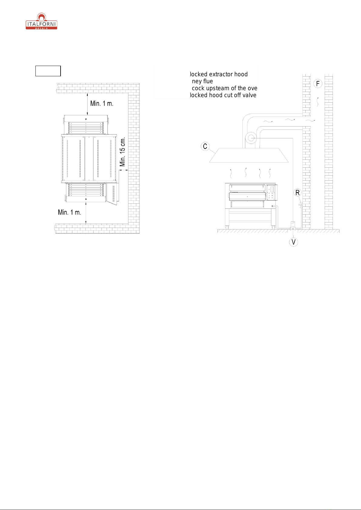
More precisely, the oven must be installed on a suitable stand or sufficiently solid surface which is perfectly
horizontal in a room with sufficient ventilation and must be used by trained staff only.
The oven must be palced under a suitable extractor hood in order to divert the cooking vapours and
combustion fumes outdoors; the extractor hood must be an interlocked one, able to interrupt the gas
feeding if the discharge of the removed combustion fumes from the room is lower than certain
parameters. The burner power can be set on two values.
If the burner should fail to ignite, a red warning light comes on and then ignition can be attempted again by
pressing the reset button. In the event of excessive or irregular heating of the cooking chamber, a safety
thermostat with automatic re-enabling is triggered; in order to signal th anomaly, on the control panel the
“over temperature” warning light comes on.

Instructions for use and maintenance
5
1.1 General warnings
Read this booklet carefully as it provides directions on safety for the oven use and maintenance. The
purpose of this manual is to inform operators of the rules and essential criteria for guaranteeing their
safety and for prolonging the working life of the oven. Before the oven is put into service this manual
must be read by all staff authorised to work on it.
This instruction booklet must be kept with the oven for future reference. If the oven is sold or
transferred, make sure that the booklet accompanies it every time, so that the new user can be
informed of its operation and the safety warnings. It is to be kept in a place which is safe, dry and can be
quickly located whenever it needs to be referred to. If it deteriorates or is lost, request a replacement
copy from your nearest service centre.
The product is carefully packed in sturdy wooden cage with nylon bubble packing to protect it from
knoks and humidity during transportation and is consigned to the forwarder in the best possible
conditions.
However we would advise you to check the packaging on taking delivery, for evidence of any signs of
damage. Should they be found they must be noted on the delivery receipt to be signed by the driver. On
unpacking the appliane, check for any signs of damage. In the event of any damage do not attempt to
use the appliance and contact your nearest service centre.
Put the appliance into service in accordance with the governing laws. These instructions are only valid
for category II2H3+ tunnel pizza oven model.
This oven is intended for the following use: cooking pizzas or similar foods. It must not be used for other
purposes; any other use is considered improper. The appliance is intended for collective and
professional use and must be operated by staff trained in its use.
Servicing, conversion to other types of gas, installation and inspection for proper working must only be
performed by qualified persons.
Each time a new part is fitted or a component adjusted, make sure that it is sealed with paint to
discourage any tampering.
For all repairs, contact an authorised service centre and always insist on original spare parts.
The following symbol denotes “hot surface”. Avoid all direct contact with such surfaces.
Use personal protective heat equipment when using the appliance.
When the appliance has reach the end of its working life, all its parts and components must be disposed
separately; devide each type of material forming the oven, e.g. stainless steel parts, thermal insulation
in ceramic fiber, refractory tiles, cables and electric devices. The disposal of such materials is regulated
by law dispositions and EU Directives and may involve penalties in case of intentional behaviours that
may cause harm to the environment and to the people. Every countries dispose the appliance
complying with the national and local laws in force in the country of use.

Instructions for use and maintenance
6
1.2 Techinical data plate and supplementary plate
The technical data plate (Fig. 1) is located on the “unloading” side of the of the oven and contains the
voltage rating and all the other information necessary for installation. The supplementary plate (Fig. 2)
sates the basic rules to be followed for correct installation.
Fig. 2
Fig. 1
FAC
SIMILE

Instructions for use and maintenance
7
1.3 Technical information
Tab. 1
Model
TS GAS
External dimension L x P x H
1420 x 2160 x 661 mm
Stand dimension L x P x H
1150 x 1330 x 622 mm
Total nominal thermal capacity
47,0 kW
Reduced thermal capacity
42,5 kW
Electrical power rating
100 W
Gas connection
ISO 7-1 da 3 / 4 “
Appliance category
II2H3+
Type of construction
B21
Electric security class
I
Voltage supply
220-230 V ~ 50 Hz
Power lead
Tipo H07RN-F 3x1,5 mm2
Gas connection nominal pressure
Liquid butan/propane gas G30/G31
Natural gas G20
: 28-30/37 mbar
: 20 mbar
Gas pressure at the injector (MAX.)
Liquid butan/propane gas G30/G31
Natural gas G20
: 27 mbar
: 9 mbar
Gas pressure at the injector (MIN.)
Liquid butan/propane gas G30/G31
Natural gas G20
: 21 mbar
: 7 mbar
Gas consumption calculated with calorific
inferior value Hiat 15° and 1013 mbar :
G 30 : 3,707 kg / h
G 31 : 3,651 kg / h
G 20 : 4,974 m3/ h
Main injector diameter
G 30/G 31 : 2 x 255 1/100 mm
G 20 : 2 x 450 1/100 mm
Primary air bushing setting
G 30/G 31 : 2 x 18 mm
G 20 : 2 x 13 mm

Instructions for use and maintenance
8
Fig. 4
Fig. 3
Views and overall
dimension
Support stand

Instructions for use and maintenance
9
CAP.2 - GENERAL INSTRUCTIONS (for the installer)
2.1 Assembly and installation place
On receipt of the oven and before proceeding with installation check that the goods supplied correspond
with the order specifications and that no damage has been caused during transit; in the event of damage or
missing parts, inform immediately and in full detail the forwarding agent (see page 4).
The installer must make sure that commissioning is carried out in accordance with the rules in force in the
country where the oven is used. He must be in possession of the necessary professional qualifications and
must follow the safety rules scrupulously. All extraordinary maintenance (any conversion to other types of
gas or parts replacement) must be carried out by qualified persons authorised by the manufacturer.
The oven must be installed in a well ventilated room with permanent ventilation openings which will
guarantee sufficient flow of combustion air and a healthy workplace in general; the ovens are classified as
type B21 and the combusted fumes must therefore be discharged outside the place where the oven is
operated by means of a suitable motorized extractor hood; the extractor hood must have a system
interlocked to the gas supply circuit and precisely the gas flow must be cut off if the discharge of the fumes
extracted by the motor of the hood is lower than certain parameters; the re-enabling can only be manual.
The oven should be positioned perfectly horizontally on the stand supplied as an optional or on a sufficiene
solid and horizontal structure, placed on four base feet, at a distance of no less than 150 mm from the rear
wall and 1000 mm from the loading and unloding sides; the oven must not be located near flammable walls
and is not suitable for installation in battery formation. For installation and the minimum ventilation
diameters in any countries, refer to the nationlal laws and directions in force. Be particularly careful to
make sure that the volume of air needed for combustion is in no way obstructed by objects placed under or
around the appliance, in particular the side holes and slits.

Instructions for use and maintenance
10
2.2 Gas connection
Before installation, make sure that the oven is set up to take the gas available. If it is not, see the paragraph
“Conversion to other types of gas” or contact the manufacturer’s service assistance dept. The connection
to the gas supply must be performed conforming to the specific installation rules by means of a rigid or
flexible pipe made only of metal, with diameters in proportion to the appliance power rating and to the
length of travel. Make sure that the pipe does not pass near the hot areas and that it is not twisted or
stretched . Between the gas supply and the oven, fit a type approved shutoff cock in a position that will
allow easy manoeuvrability for opening and closing. Once the appliance is installed, carry out a soundness
test on the whole gas circuit, using a leak searching spray or other non-corrosive foaming substance (do not
use naked flames for this operation). The joints of the copper pipes must be made using mechanical
couplings without gaskets.
The oven is equipped with a type 3/ 4 “ ISO 7-1 gas connector .
Key:
C
=
Interlocked extractor hood
F
=
Chimney flue
R
=
Stop cock upsteam of the oven
V
=
Interlocked hood cut off valve
Fig. 5
Installation

Instructions for use and maintenance
11
2.3 Electrical connection
Connection to the electrical power supply must be carried out according to the applicable rules. Before
making the electrical connection make sure that the voltage and frequency shown on the technical data
plate are the same as those of the power supply. The power lead must be flexible, with characteristics of
no less than the type with H07RN-F polychloroprene rubber insulation. The lead should be connected to
the terminal block according to the wiring diagram enclosed with the appliance, and then secured with a
cable clamp.
The wiring pattern is as follows:
Yellow/green wire earth
Blue wire neutral N
Brown wire live L
If the appliance is to be permanently connected to the mains power supply, an omnipolar safety switch of
suitable capacity with a contact separation of at least 3 mm must be fitted upstream of it.
Make sure that the power lead does not come into contact with hot or sharp parts.
If the plug continues to spark during ignition, and the burnes becomes blocked, swap the live wire with the
neutral.
It is essential for the appliance to be properly earthed and included in an equipotential system; this
connection is carried out with the stop screw marked by the
symbol to be found behind the appliance. The equipotential wire must have a diameter of at least 10
mm2.
CAP.3 - COMMISSIONING (for the installator)
3.1 Checking the nominal thermal capacity
The nominal thermal capacity must be checked by the authorised engineer or by the competent Agency,
according to the information contained in this user manual. This check must be made for new installations
or for conversions to other types of gas and after all extraordinary maintenance.
There is no way of setting the nominal thermal capacity other than measuring the correct supply pressure
and checking that the injectors used are the correct ones. The sealed (for example with paint) components
must never be disturbed. Checking the nominal thermal capacity is carried out using a counter and a
chronometer. The exact volume of gas that must pass for each unit of time can be seen in the technical
data table. This value must be kept within the prescribed range, with a tolerance of ± 5%.
If any deviation is found a check should be made that the correct size injectors have been fitted.

Instructions for use and maintenance
12
3.2 Checking the gas supply pressure
Before putting the oven into service, a check must be made to see whether it is suitable for the family and
type of gas available, as stated on the technical data plate. If it is not, see the paragraph “Conversion to
other types of gas”.
The gas supply pressure is measured, with the appliance in operation, using a pressure gauge for liquids
(for example a “U “type pressure gauge with a minimum 0.1 mbar resolution). To carry out this check,
access the gas valve by removing the right side panel from the oven; then, using flexible pipes, connect the
pressure gauge “ E “ to the pressure inlet “ V “ and pressure outlet “ X “ of the gas valve after removing
the relative fixing screws “ U “ and “ Z “ (see Fig 6).
Measure the incoming pressure: if this is not within the range of values shown in table 2, the oven must
under no circumstances be put into operation. The gas supply agency must be informed.
Tab. 2
Type of gas
Incoming gas pressure (mbar)
Normal
Minimum
Maximum
Natural gas G20
20
17
25
Liquid gas G30/G31
30/37
20/25
35/45
Key:
A
=
Minimum pressure regulator screw
B
=
Maximum pressure regulator nut
E
=
U-Type pressure gauge
R
=
Pressure regulator
V
=
Incoming gas pressure plug
X
=
Outcoming gas pressure plug
Fig. 6
V
X

Instructions for use and maintenance
13
The outgoing pressure must be checked and, if necessary, corrected using the screw “A ”and the nut
“B ”located on the pressure regulator “R ”.After removing the plastic cap, adjust the outgoing pressure
by means of the nut “B ” (with the burner is working at its maximum capacity), then adjust the outgoing
pressure by means of the screw “A ” (with the burner working at reduced capacity); follow the indications
in table 3.
Tab. 3
Gas type
Outgoing pressure
with burner at
maximum
(mbar)
Procedure to be
followed
Outgoing pressure
with the burner at
minimum
(mbar)
Procedure to be
followed
Natural gas
G20
9
Turn nut “B” untill the
valve on the left is
reached.
7
Turn nut “A” untill
the valve on the left
is reached.
Liquid gas
G30/G31
27
Exclude the pressure
regulator by tightening
nut “B” fully check the
pressure valve on the
left is reached.
21
Turn nut “A” untill
the valve on the left
is reached.
After measuring the gas supply pressure, turn oven off, close the gas cock located upsteam and remove the
flexible pipes of the pressure gauge from the pressure inlet and outlet. Refit the sealing screws on the
pressure inlet and outlet, tighten the regulator cover screw and seal it with paint to discourage any
tampering.

Instructions for use and maintenance
14
3.3 Conversion to other type of gas
Gas spare parts are supplied with the oven; if any spare parts are needed, contact the manufacturer’s
service assistance dept. Conversion must be carried out by a qualified engineer. Referring to table 4,
change the two main injectors and regulate the primary air through the two relative brass bushings.
Then regulate the outgoing pressure from the valve by following the procedure described in the preceding
paragraph.
WARNING - Carry out this operation only after closing the gas shutoff cock located upstream of the oven
and disconnecting the oven electrical power supply. Check that the diameter of the injector is stamped on
it in 1/100 of a mm.
Perform the following operations in sequence:
To gain access to the devices to adjust and replace, remove the oven lateral panel (in the control panel
side) after removing the four fixing screws and disconnetting the electrical connessions to the cooloing
fan.
With a suitable tool, undo and substitute the two injectors “U“ with the correct ones for the gas supply.
Undo the fixing screw and regulate the air bushings “B“ to the correct distance H, according to the
settings in tables 4 and in Fig. 7 . Then tighten the fixing screw and seal it with paint.
Refit the oven lateral panel by proceding in reverse order.
WARNING - After each conversion to new gas, always:
Add an indelible sticker to the plate showing the data of the new installation.
Proceed with the appropriate gas circuit soundness test.
Carry out an operating test checking:
that the burner branches ignite properly, the stability and appearance of the flames.
to make sure there is no flame separation with the burner cold or light-back when the burner is hot
denoting that the primary air is properly adjusted.
Key:
B
=
Primary air bushing
U
=
Injector
Tab. 4
Gas
Injector
diameter
Distance
H
G30/G31
2 x 2551/100 mm
18 mm
G20
2 x 4501/100 mm
13 mm
Fig. 7

Instructions for use and maintenance
15
3.4 Instructions for changing certain components
WARNING - Carry out this operation only after closing the gas shutoff cock located upstream of the
appliance and disconnecting the oven electrical power supply. Any component changes must be carried out
by an authorised installer.
A) Gas valve
Remove the lateral panel (control board side) by undoing the four fixing screws.
Disconnect the eletrical connessions to the gas electro-valve.
Undo the inlet and outlet connections on the gas electro-valve and remove the inlet and oulet copper
gas pipes.
Undo the four screws that fix the gas electro-valve to the base and fit a new valve.
Re-assemble the various parts in reverse order.
B) Electrical components on control panel
Remove the outer panel of the control panel by undoing the four fixing screws.
Each component can be replaced by detaching their respective electric wirings and then re-assembling
the various part in reverse order.
Caution! When changing the safety thermostat and the pyrometer, pay attention to the capillaries and
bulbs which have to be positioned in their appropriate seats.
C) Burner
Remove the two lateral oven panel by undoing the fixing screws.
Detach the gas pipe from the gas ramp which feeds the burner.
Detach the electrical connections to the electrodes, on both sides of the burner.
Remove the burner with caution and fit a new one.
Re-assemble the various parts in reverse order.
D) Ignition and sensing plugs
Remove the two lateral oven panel by undoing the fixing screws.
Detach the electrical connections to the plugs.
Each plug couple is formed by one ignition plug and one sensing plug: do not swap the relative
electrical connections.
Change the plug and reattach the connections.
Re-assemble the various parts in reverse order.
E) Refractory tiles
In case of breaking or damage, the refractory tiles can be extracted and replaced by removing the four
rivets (two on each side) and then fixed with new rivets.
Notice: Pay attention when substituting the gas pipings or pipe fittings: conical head mechanical couplings
or appropriate sealing gas guarantee the tightness of the circuit ; please refer to the gas circuit diagram.

Instructions for use and maintenance
16
3.5 Fault finding
A) The oven will not switch on. Possible causes:
No electrical power.
Electrical wires disconnected.
B) The burner does not ignite, continuously defaults or goes out. Possible causes:
Ignition plug is not properly secured, is badly connected, is wrongly positionned or the wire is damaged.
The polarity of the electrical wire is wrong. Invert the live and neutral by rotating the pin on the plug.
Faulty gas valve.
Insufficient pressure in gas pipes or air the circuit.
Gas pressure regulator on the valve not properly arranged.
Obstructed injector.
Flame outlets on burner are obstructed
Faulty work thermostat.
Electrical wires disconnected.
C) Temperature cannot be regulated. Possible causes:
Faulty work thermostat or thermocouple not properly fitted.
Faulty electronic temperature control board.
Fig. 8
Key:
A
=
Ignition electrod
B
=
Burner
R
=
Sensing electrod
Electrodes position

Instructions for use and maintenance
17
CAP.4 –OPERATING INSTRUCTIONS (for the user)
WARNING:
This gas oven is intended for professional use and must only be operated by staff trained in its use.
The user must only responsibly use the appliance and do the ordinary cleaning.
All installation, commissioning and servicing must only be carried out by installers authorised by the
manufacturer, in accordance with the national rules that apply.
It is advisable to have the oven periodically checked by a specialised technician to maintain perfect
working order; for this reason, the provision of a servicing contract is strongly recommended.
4.1 Start Up
Before using on the oven for the first time, clean it thoroughly to remove the film of grease.
Check that there are no obstructions to the airflow to the burner and in general to the room
ventilation. Do not block or leave anything on the combusted gas outlet or on the oven chimney. Check
the proper working efficiency of the extractor hood and chimney flue.
Supervise the oven while it is working. Pay attention to the hot parts and moving parts.
Do not block the loading and unloading sides of the oven; a minimum height of the refractory tiles is
fixed in order to ensure a proper combusted fumes discharge when the burner is working.
It is advisable to activate the belt before starting up the burner, in order to avoid the overheating of the
refractory tiles and the conveyor chain.
Close the gas shutoff cock located upstream and disconnect the electrical power supply after use.
Key:
1
=
Main switch
2
=
Belt speed variator
3
=
Belt start switch
4
=
Safety thermostat warning light
5
=
Burner/Belt start button
6
=
Temperature setting digital display
7
=
Burner reset button
8
=
Burner power selection switch
9
=
Emergenrcy switch
Fig. 9

Instructions for use and maintenance
18
Turning on (Fig. 9)
Open the gas shutoff cock upstream of the oven and plug in the electrical power.
Turn the main switch “ 1 “ to “ON” position.
Turn the belt start switch “ 3 “ to “ON” position.
Turn the belt speed variator “ 2 “ to the required position.
Set the required baking temperature on the digital display “ 6 “ by pressing the “SET” key and then the
increasing or decreasing keys (+ or -). The temperature can be set up to 450°C.
Turn the burner power selection switch “ 8 “ in the required position. The “MAX” position allows you to
reach the baking temperature faster, the “MIN” position allows you to maintain the temperature while
saving energy.
Press the start green button “ 5 “ which activates the belt and turns the burner on.
Burner ignition can be checked through the inspection glass and the aeration slots placed in the lateral
panel of the oven(opposite side of control panel); it's also possible to see the flames through the
working plan sides, on the sides of the refractory tiles.
In case of lack of gas flow, the burner defaults and the red warning light on “ 7 “ button comes on; press
the reset button to restart; if the blockage persists, it is necessary to invert the polarity of the electrical
wiring; in case of continuous breakdown, contact the manufacturer's service center.
If the warning light “ 4 “ comes on, the baking chamber is in over-temperature and the working
thermostat connected to the digital board is not measuring the temperature properly; the safety
thermostat has cut in.
Turning off
Close the gas shutoff cock upstream of the oven.
Set on the digital display a baking temperature lower than the room temperature.
Let the belt turn for few minutes for allowing it to cool down and avoid the refractory overheating.
At the end of the work, turn the main switch “ 1 “ in “OFF” position and disconnect the electrical
power.

Instructions for use and maintenance
19
Safety Device
The oven is equipped with an automatic safety thermostat which cuts in when the baking chamber is in
over-temperature; the “ OVER TEMPERATURE” warning light on the control panel comes on; contact the
service center for solving the anomaly.
A red emergency button “ 9 “ is located on the control panel: it can be easily reached in case of emergency;
by pressing it, the oven will stop entirely.
The oven is protected by two fuses (one of 6A and one of 2A) in case of overcurrent or short-circuit.
Flame safety
Two flame sensing electrodes connected to two independent control units are placed on the burner
branches; in case of lack of flame on one of the two electrodes, the supply of gas is cut off.
Residual hazards
Some parts of the oven, the two ash-drawers and the sides of the working plan reach high temperatures;
some of these parts are marked by the symbol shown at page 5. Avoid all direct contact with such surfaces
and if they have to be cleaned, wait until they have sufficiently cooled down.
The oven is formed by some moving parts such us the conveyor belt and its gears: do not bring your hands
or working tools near to the refractories in the area where they reverse the movement (especially in the
unloading side).

Instructions for use and maintenance
20
CAP.5 –CLEANING AND ROUTINE MAINTENANCE
The oven must be cleaned regularly to ensure the best working efficiency and maximum performance. In
the event of malfunction, do not attempt to remedy the problem but contact the dealer or his technical
assistance service which will deal with the problem. Never attempt to dismantle the appliance; all repairs
must be carried out by qualified engineers.
Pay attention to the following procedures :
Before cleaning the oven, make sure that the gas and electrical power supplies are turned off. Allow the
appliance to cool down.
Always clean the oven when it is cool and at room temperature.
Clean the steel parts every day with warm soapy water or suitable detergents, rinsing thoroughly and
drying well. Do not use detergents that contain chlorine (bleach, muriatic acid, etc. ) and never clean the
steel parts with wire wool, brushes or scrapers that could leave behind ferrous deposits subject to
oxidation and therefore rust. Clean the refractory tiles with appropriate non-metallic brushes.
Do not allow food substances (especially acidic ones such as salt, vinegar, lemon … ) to remain on the
stainless steel parts as these could deteriorate as a result.
Do not wash the appliance using direct jets of water, as any water infiltrations could compromise the
safety of the oven.
Do not use corrosive substances (for example muriatic acid) to clean the bed of the oven.
Every 40 hours of operation is necessary to grease the conveyor chain with the appropriate lubricant
supplied.
The oven should be checked periodically. All servicing and repairs must be carried out by authorised and
qualified engineers. In particular, it is necessary to grease the belt bearing every 200 working hours; the
bearings can be reached by removing the covers with slots in the sides of the working plan. This operation
must always be carried on after having disconnected the power supply and with the oven at room
temperature.
Table of contents
Other Italforni Oven manuals