Itelco-Clima CWP-HP Manual

English
Water cooled water chillers : cooling only, condenserless and heat pump
versions
Refroidisseurs de liquide à condensation par eau : versions froid seul, sans
condenseur et pompe à chaleur
Installation and maintenance manual
Manuel d’installation et de maintenance
IOM CWP-N.1GBF
Date : May / Mai 2006
Supersedes / Annule et remplace : IMW 910.2M/12.01
CWP-CO/CWP-RC/CWP-HP
02 ÷ 35
8
136 kW
9
164 kW
Français

Page 1
Table of contents
English
1 FOREWORD
1.1 Introduction 2
1.2 Warranty 2
1.3 Emergency stop/Normal stop 2
1.4 An introduction to this manual 2
2 SAFETY
2.1 Foreword 3
2.2 Definitions 3
2.3 Access to the unit 4
2.4 General precautions 4
2.5 Precautions against residual risks 4
2.6 Precautions during maintenance
operations 5
2.7 Safety labels 6
2.8 Safety regulations 7
3 TRANSPORT, LIFTING
AND POSITIONING
3.1 Inspection 10
3.2 Unit Handling 10
3.3 Anchoring 10
3.4 Storage 10
4 INSTALLATION
4.1 Positioning of the unit 11
4.2 Vibration Isolators 11
4.3 External hydraulic circuit 11
4.4 Hydraulic connection
of the condenser 12
4.5 Hydraulic connection 13
4.6 Power supply 13
4.7 Electrical connections 13
5 START-UP
5.1 Preliminary check 14
5.2 Start-up 14
5.3 Checking the operation 15
5.4 Delivery to the customer 15
6 CONTROL SYSTEM
6.1 CWP Control system µchiller 16
6.2 High Pressure Control 18
6.3 Low Pressure Control 18
6.4 Heat Exchanger Heater Thermostat 18
6.5 Pressostatic Valve Kit (Optional) 18
7 GENERAL DESCRIPTION
7.1 Introduction 19
7.2 General Specifications 19
7.3 Compressors 19
7.4 Refrigeration circuits 19
7.5 Evaporator 19
7.6 Condenser (except for CWP-RC) 19
7.7 Switchboard 19
8 TECHNICAL DATA
8.1 Pressure drops 23
8.2 Technical data 24
8.3 Electrical data 29
8.4 Overall dimensions 30
8.5 Service spaces 33
9 MAINTENANCE
9.1 General requirements 34
9.2 Planned maintenance 34
9.3 Refrigerant charge 35
9.4 Compressor 35
9.5 Condenser 35
9.6 Dehydrating filter 35
9.7 Sight glass 35
9.8 Thermostatic expansion valve 36
9.9 Evaporator 36
10 TROUBLESHOOTING 37
11 SPARE PARTS
11.1 Spare part list 39
11.2 Oil for compressors 39
11.3 Wiring diagrams 39
12 DISMANTLING, DEMOLITION
AND SCRAPPING
12.1 Generalities 40
Table of contents
Manuale CWP 4.11.2005 11:55 Pagina 1

Page 2
Foreword
1 FOREWORD
1.1 Introduction
Itelco-Clima units, manufactured to state-of-the-art de-
sign and implementation standards, ensure top per-
formance, reliability and fitness to any type of air-
conditioning systems.
These units are designed for cooling water (and for
water heating in heat pump models) and are unfit for
any purposes other than those specified in this manu-
al.
This manual includes all the information required for
a proper installation of the units, as well as the rele-
vant operating and maintenance instructions.
It is therefore recommended to read this manual
carefully before installation or any operation on the
machine. The chiller installation and maintenance
must be carried out by skilled personnel only (where
possible, by one of Itelco-Clima’s Authorised Service
Centers).
The manufacturer may not be held liable for any
damage to people or property caused by improper
installation, start-up and/or improper use of the unit
and/or failure to implement the procedures and in-
structions included in this manual.
1.2 Warranty
These units are delivered complete, tested and ready
for being operated. Any form of warranty will be-
come null and void in the event that the appliance is
modified without Itelco-Clima’s preliminary written
authorisation.
This warranty shall apply providing that the installa-
tion instructions have been complied with (either is-
sued by’Itelco-Clima, or deriving from the current
practice), and the Form 1 (“Start-up”) has been filled-
in and mailed to ’Itelco-Clima (attn. After-Sales Ser-
vice).
In order for this warranty to be valid, the following
conditions shall be met:
hThe machine must be operated only from Autho-
rised After-Sales Service.
hMaintenance must be performed only by skilled
personnel - from one of Itelco-Clima’s Authorised
After-Sales Centers.
hUse only original Itelco-Clima spare parts.
hCarry out all the planned maintenance provided
for by this manual in a timely and proper way.
Failure to comply with any of these conditions will
automatically void the warranty.
1.3 Emergency stop / Normal stop
The emergency stop of the unit can be enabled using
the master switch on the control panel (move down
the lever).
For a normal stop, press the relevant push-buttons.
To restart the appliance, follow the procedure de-
tailed in this manual.
1.4 An introduction to the manual
For safety reasons, it is imperative to follow the in-
structions given in this manual. In case of any dam-
age caused by non-compliance with these instruc-
tions, the warranty will immediately become null and
void.
Conventions used throughout the manual:
The Danger sign recalls your attention to a
certain procedure or practice which, if not
followed, may result in serious damage to
people and property.
The Warning sign precedes those proce-
dures that, if not followed, may result in seri-
ous damage to the appliance.
The Notes contain important observations.
The Useful Tips provide valuable informa-
tion that optimises the efficiency of the ap-
pliance.
This manual and its contents, as well as the docu-
mentation which accompanies the unit, are and re-
main the property of Constructor, which reserves any
and all rights thereon. This manual may not be
copied, in whole or in part, without Constructor’s
written authorization.
USEFUL TIPS
Manuale CWP 4.11.2005 11:55 Pagina 2

Page 3
English
Safety
2 SAFETY
2.1 Foreword
These units must be installed in conformity with the
provisions of Machinery Directive 98/37/EC, Low
Voltage Directive 73/23/EC, Pressure Vessels Direc-
tive 97/23/EC, Electromagnetic Interference Direc-
tive 89/336/EC, as well as with other regulations
applicable in the country of installation. If these pro-
visions are not complied with, the unit must not be
operated.
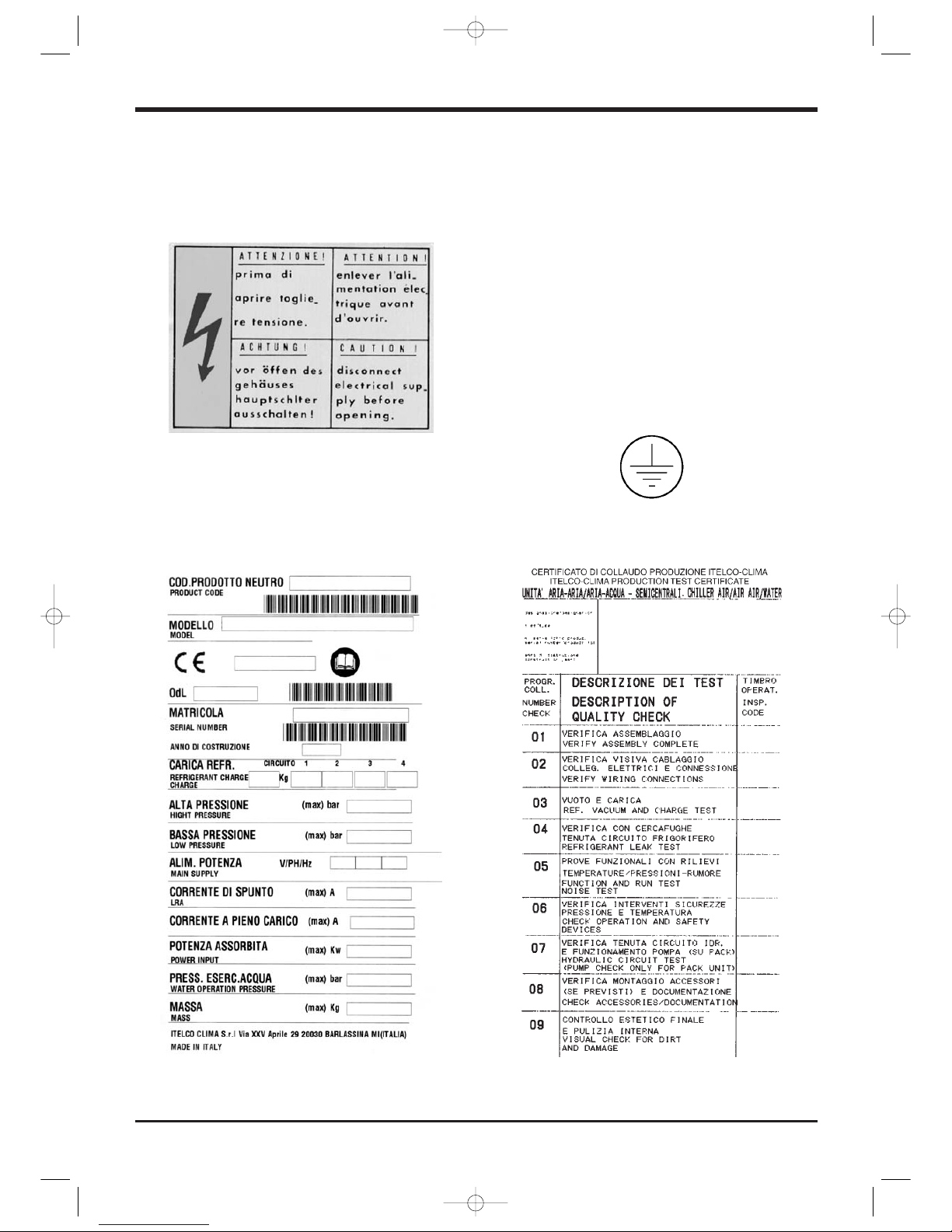
The unit must be grounded, and no installa-
tion and/or maintenance operations may
be carried out before deenergising the elec-
trical panel of the unit.
Failure to respect the safety measures mentioned
above may result in electrocution hazard and fire in
the presence of any short-circuits.
Inside the heat exchangers, the compres-
sors and the refrigeration lines, this unit
contains liquid and gaseous refrigerant un-
der pressure. The release of this refrigerant
may be dangerous and cause injuries.
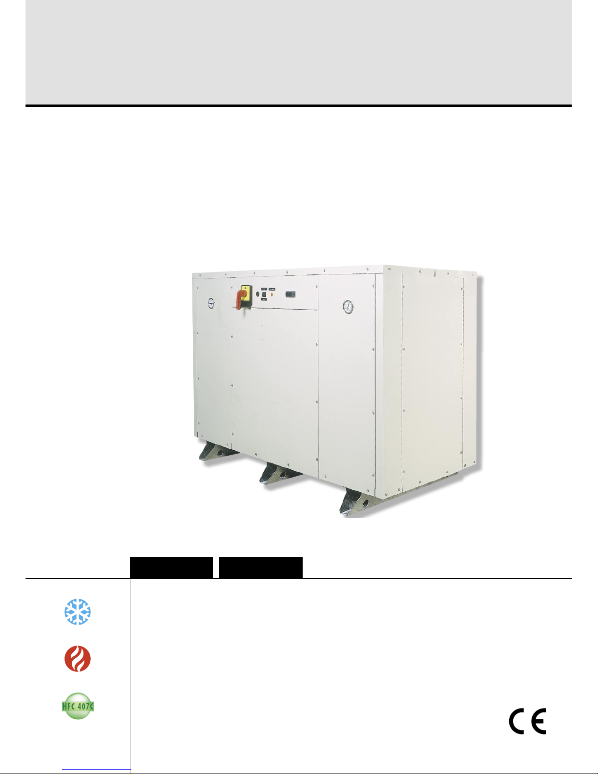
The units are not designed to be operated
with natural refrigerants, such as hydrocar-
bons. Itelco-Clima may not be held liable
for any problems deriving from the replace-
ment of original refrigerant or the introduc-
tion of hydrocarbons.
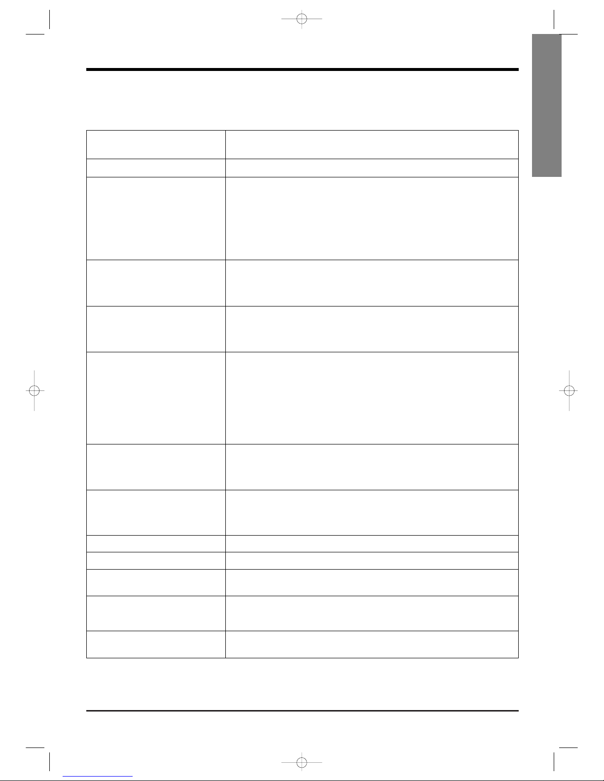
Itelco-Clima units are designed and manufactured
according to the requirements of European Standard
PED 97/23/EC (pressure vessels).
– The used refrigerants are included in group II (non-
hazardous fluids).
– The maximum working pressure values are men-
tioned on the unit’s data plate.
– Suitable safety devices (pressure switches and safe-
ty valves) have been provided, to prevent any
anomalous overpressure inside the plant.
– The vents of the safety valves are positioned and
oriented in such a way as to reduce the risk of con-
tact with the operator, in the event that the valve is
operated. Anyway, the installer will convey the dis-
charge of the valves far from the unit.
It is the User’s responsibility to ensure that
the unit is fit for the conditions of intended
use and that both installation and mainte-
nance are carried out by experienced per-
sonnel, capable of respecting all the recom-
mendations provided by this manual. It is
important that the unit is adequately sup-
ported, as detailed in this manual. Non-
compliance with these recommendations
may create hazardous situations for the
personnel.
The unit must rest on a base which meets
the characteristics specified in this manual;
a base with inadequate characteristics is
likely to become a source of serious injury
to the personnel.
The unit has not been design to withstand
loads and/or stress that may be transmitted
by adjacent units, piping and/or structures.
Each external load or stress transmitted to
the unit may break or cause breakdowns in
the unit’s structure, as well as serious dan-
gers to people. In these cases, any form of
warranty will automatically become null
and void.
The packaging material must not be dis-
posed of in the surrounding environment or
burnt.
2.2 Definitions
OWNER: means the legal representative of the com-
pany, body or individual who owns the plant where
Itelco-Clima unit has been installed; he/she has the
responsibility of making sure that all the safety regu-
lations specified in this manual are complied with,
along with the national laws in force.
INSTALLER: means the legal representative of the
company who has been given by the owner the job
of positioning and performing the hydraulic, electric
and other connections of Itelco-Clima unit to the
plant: he/she is responsible for handling and prop-
erly installing the appliance, as specified in this man-
ual and according to the national regulations in
force.
OPERATOR: means a person authorised by the own-
er to do on Itelco-Clima unit all the regulation and
control operations expressly described in this manu-
al, that must be strictly complied with, without ex-
ceeding the scope of the tasks entrusted to him.
Manuale CWP 4.11.2005 11:55 Pagina 3

Page 4
Safety
ENGINEER: means a person authorised directly by
Itelco-Clima or, in all EC countries, excluding Italy,
under his full responsibility, by the distributor of Itel-
co-Clima product, to perform any routine and extra-
ordinary maintenance operations, as well as any
regulation, control, servicing operations and the re-
placement of pieces, as may be necessary during the
life of the unit.
2.3 Access to the unit
The unit must be placed in an area which can be ac-
cessed also by OPERATORS and ENGINEERS; oth-
erwise the unit must be surrounded by a fence at not
less than 2 meters from the external surface of the
machine.
OPERATORS and ENGINEERS must enter the fenced
area only after wearing suitable clothing (safety
shoes, gloves, helmet etc.). The INSTALLER personnel
or any other visitor must always be accompanied by
an OPERATOR.
For no reason shall any unauthorised personnel be
left alone in contact with the unit.
2.4 General precautions
The OPERATOR must simply use the controls of the
unit; he must not open any panel, other than the one
providing access to the control module.
The INSTALLER must simply work on the connections
between plant and machine; he must not open any
panels of the machine and he must not enable any
control.
When you approach or work on the unit, follow the
precautions listed below:
hdo not wear loose clothing or jewellery or any oth-
er accessory tat may be caught in moving parts
hwear suitable personal protective equipment
(gloves, goggles etc.) when you have to work in
the presence of free flames (welding operations) or
with compressed air
hif the unit is placed in a closed room, wear ear pro-
tection devices
hcut off connecting pipes, drain them in order to
balance the pressure to the atmospheric value be-
fore disconnecting them, disassemble connections,
filters, joints or other line items
hdo not use your hands to check for any pressure
drops
huse tools in a good state of repair; be sure to have
understood the instructions before using them
hbe sure to have removed all tools, electrical cables
and any other objects before closing and starting
the unit again
2.5 Precautions against residual risks
Prevention of residual risks caused by the
control system
hbe sure to have perfectly understood the operating
instructions before carrying out any operation on
the control panel
hwhen you have to work on the control panel, keep
always the operating instructions within reach
hstart the unit only after you have checked its perfect
connection to the plant
hpromptly inform the ENGINEER about any alarm
involving the unit
hdo not reset manual restoration alarms unless you
have identified and removed their cause
Prevention of residual mechanical risks
hinstall the unit according to the instructions provid-
ed in this manual
hcarry out all the periodical maintenance opera-
tions prescribed by this manual
hwear a protective helmet before accessing the inte-
rior of the unit
hbefore opening any panelling of the machine,
make sure that it is secured to it by hinges
hdo not remove the guards from moving elements
while the unit is running
hcheck the correct position of the moving elements’
guards before restarting the unit
Prevention of residual electrical risks
hconnect the unit to the mains according to the in-
structions provided in this manual
hperiodically carry out all the maintenance opera-
tions specified by this manual
hdisconnect the unit from the mains by the external
disconnecting switch before opening the electrical
board
hcheck the proper grounding of the unit before start-
up
hcheck all the electrical connections, the connecting
cables, and in particular the insulation; replace
worn or damaged cables
hperiodically check the board’s internal wiring
hdo not use cables having an inadequate section or
flying connections, even for limited periods of time
or in an emergency
Manuale CWP 4.11.2005 11:55 Pagina 4

Page 5
English
Safety
Prevention of other residual risks
hmake sure that the connections to the unit conform
to the instructions provided in this manual and on
the unit’s panelling
hif you have to disassemble a piece, make sure that
it has been properly mounted again before restart-
ing the unit
hdo not touch the delivery pipes from the compres-
sor, the compressor and any other piping or com-
ponent inside the machine before wearing protec-
tive gloves
hkeep a fire extinguisher fir for electrical appliances
near the machine
hon the units installed indoor, connect the safety
valve of the refrigeration circuit to a piping net-
work that can channel any overflowing refrigerant
outside
hremove and leak of fluid inside and outside the unit
hcollect the waste liquids and dry any oil spillage
hperiodically clean the compressor compartment, to
remove any fouling
hdo not store flammable liquids near the unit
hdo not disperse the refrigerant and the lubricating
oil into the environment
hweld only empty pipes; do not approach flames or
other sources of heat to refrigerant pipes
hdo not bend/hit pipes containing fluids under pres-
sure
2.6 Precautions during maintenance
operations
Maintenance operations can be carried out by au-
thorised technicians only.
Before performing any maintenance operations:
hdisconnect the unit from the mains with the external
disconnecting switch
hplace a warning sign “do not turn on - mainte-
nance in progress” on the external disconnecting
switch
hmake sure that on-off remote controls are inhibited
hwear suitable personal protective equipment (hel-
met, safety gloves, goggles and shoes etc.)
To carry out any measurements or checks which re-
quire the activation of the machine:
hwork with the electrical board open only for the
necessary time
hclose the electrical board as soon as the measure-
ment or check has been completed
The following precautions must be always adopted:
hdo not scatter the fluids of the refrigeration circuit
in the surrounding environment
hwhen replacing an eprom or electronic cards, use
always suitable devices (extractor, antistatic
bracelet, etc.)
hto replace a compressor, the evaporator, the con-
densing coils or any other weighty element, make
sure that the lifting equipment is consistent with the
weight to be lifted
hcontact Itelco-Clima for any modifications to the re-
frigeration, hydraulic or wiring diagram of the
unit, as well as to its control logics
hcontact Itelco-Clima if it is necessary to perform
very difficult disassembly and assembly operations
huse only original spare parts purchased directly
from Itelco-Clima or the official retailers of the com-
panies on the recommended spare parts list
hcontact Itelco-Clima if it is necessary to handle the
unit one year after its positioning on site or if you
wish to dismantle it.
Manuale CWP 4.11.2005 11:55 Pagina 5

Page 6
Grounding connection - On the electrical
board, adjacent to the connection
Final Test Certificate -
Inside the external door
Fitting identification -
Adjacent to fittings
EIN - INLET
ENTRÉE - ENTRATA
AUS - OUTLET
SORTIE - USCITA
Safety
2.7 Safety labels
The labels below will be affixed to each unit in the indicated point:
Identification of the unit -
Outside, on the right-hand front column
Electrical warning
Adjacent to the master switch
Manuale CWP 4.11.2005 11:56 Pagina 6

Page 7
English
Safety
2.8 Safety regulations
Refrigerant data
Toxicity Low
Contact with skin If sprayed, the refrigerant is likely to cause frost burns. If absorbed by
the skin, the danger is very limited; it may cause a slight irritation, and
the liquid is degreasing. Unfreeze the affected skin with water. Remove
the contaminated clothes with great care - in the presence of frost
burns, the clothes may stick to the skin. Wash with plenty of warm wa-
ter the affected skin.
In the presence of symptoms such as irritation or blisters, obtain med-
ical attention.
Contact with eyes
Ingestion
Inhalation
Recommendations
Prolonged exposure
Vapours do not cause harmful effects.
The spraying of refrigerant may cause frost burns. Wash immediately
with a proper solution or with tap water for at least 10 minutes, and
then obtain medical attention.
Very unlikely - should something happen, it will cause frost burns.
Do not induce vomiting. Only if the patient is conscious, wash out
mouth with water and give some 250 ml of water to drink. Then, obtain
medical attention.
R407C: remarkable concentrations in the air may have an anaesthetic
effect, up to fainting. The exposure to considerable amounts may cause
irregular heartbeat, up to the sudden death of the patient. Very high
concentrations may result in the risk of asphyxia, due to the reduction in
the oxygen percentage in the atmosphere. Remove the patient to fresh
air and keep warm and at rest.
If necessary, give oxygen. In case of breathing difficulties or arrest, pro-
ceed with artificial respiration. In case of cardiac arrest, proceed with
cardiac massage. Then, obtain medical attention.
Semiotics or support therapy is recommended. Cardiac sensitisation
has been observed that, in the presence of circulating catecholamines
such as adrenalin, may cause cardiac arrhythmia and accordingly, in
case of exposure to high concentrations, cardiac arrest.
R407C: a study on the effects of exposure to 50,000 ppm during the
whole life of rats has identified the development of benign testicle tu-
mour. This situation should therefore be negligible for personnel ex-
posed to concentrations equal to or lower than professional levels.
Professional levels
Stability R407C: Not specified
R407C: Recommended threshold: 1000 ppm v/v - 8 hours TWA.
Conditions to avoid Do not use in the presence of flames, burning surfaces and excess hu-
midity.
Safety data: R407C
Hazardous reactions May react with sodium, potassium, barium and other alkaline metals.
Incompatible substances: magnesium and alloys with magnesium con-
centrations > 2%.
Hazardous decomposition
products R407C: Halogen acids produced by thermal decomposition and hy-
drolysis.
Manuale CWP 4.11.2005 11:56 Pagina 7

Page 8
Respiratory system protection
Storage
Protective clothing
Accidental release measures
Disposal
Fire fighting information
Cylinders
Protective fire fighting
equipment
If you are in doubt about the concentration in the atmosphere, it is rec-
ommended to wear a respirator approved by an accident-prevention
Authority, of the independent or oxygen type.
Cylinders must be stored in a dry and fresh place, free from any fire
hazard, far from direct sunlight or other sources of heat, radiators etc.
Keep a temperature below 45°C.
Wear overalls, protective gloves and goggles or a mask.
It is important to wear protective clothing and a respirator. Stop the
source of the leak, if you can do this without danger. Negligible leaks
can be left evaporating under the sun, providing that the room is well
ventilated. Considerable leaks: ventilate the room. Reduce the leak with
sand, earth or other absorbing substances. Make sure that the liquid
does is not channelled into gutters, sewers or pits where the vapours
are likely to create a stuffy atmosphere.
The best method is recovery and recycling. If this method is not practi-
cable, dispose according to an approved procedure, that shall ensure
the absorption and neutralization of acids and toxic agents.
R407C: Not flammable in the atmosphere.
In case of fire, wear an independent respirator and protective clothing.
The cylinders, if exposed to fire, shall be cooled by water jets; other-
wise, if heated, they may explode.
General precautions Do not inhale concentrated vapours. Their concentration in the atmos-
phere should not exceed the minimum preset values and should be
maintained below the professional threshold. Being more weighty than
the air, the vapour concentrates on the bottom, in narrow areas. There-
fore, the exhaust system must work at low level.
Safety
Manuale CWP 4.11.2005 11:56 Pagina 8

Page 9
English
Safety
Refrigerant oil data Safety data: Polyolester oil (POE)
Classification
Contact with skin
Contact with eyes
Ingestion
Inhalation
Conditions to avoid
Protection of the respiratory
system
Protective clothing
Accidental release measures
Disposal
Fire fighting information
Cylinders
Fire fighting protective
equipment
Not harmful
May cause slight irritation. Does not require first aid measures. It is rec-
ommended to follow usual personal hygiene measures, including wash-
ing the exposed skin with soap and water several times a day. It is also
recommended to wash your overalls at least once a week.
Wash thoroughly with a suitable solution or tap water.
Seek medical advice immediately.
Strong oxidising substances, caustic or acid solutions, excess heat.
May corrode some types of paint or rubber.
Use in well ventilated rooms.
Always wear protective goggles or a mask. Wearing protective gloves
is not mandatory, but is recommended in case of prolonged exposure
to refrigerant oil.
It is important to wear protective clothing and, especially, goggles.
Stop the source of the leak. Reduce the leak with absorbing substances
(sand, sawdust or any other absorbing material available on the mar-
ket).
The refrigerant oil and its waste will be disposed of in an approved in-
cinerator, in conformity with the provisions and the local regulations
applicable to oil waste.
In the presence of hot liquid or flames, use dry powder, carbon dioxide
or foam. If the leak is not burning, use a water jet to remove any
vapours and to protect the personnel responsible for stopping the leak.
The cylinders exposed to a fire will be cooled with water jets in case of
fire.
In case of fire, wear an independent respirator.
Manuale CWP 4.11.2005 11:56 Pagina 9

Page 10
Transport, Lifting and Positioning
3 TRANSPORT, LIFTING
AND POSITIONING
Refrigerators are supplied assembled. The equip-
ment are full of refrigerant and oil, in the quantity re-
quired for a proper operation.
3.1 Inspection
When the unit is delivered, it is recommended to
check it carefully and to identify any damage oc-
curred during transportation. The goods are shipped
ex-factory, at the buyer’s risk. Check that the delivery
includes all the components listed in the order.
In case of damage, note it down on the carrier’s de-
livery note and issue a claim according to the instruc-
tions provided in the delivery note.
In the presence of any serious damage, that does not
affect the surface only, it is recommended to inform
Itelco-Clima immediately.
Please note that Itelco-Clima may not be held liable
for any damage to the equipment during transporta-
tion, even though the carrier has been appointed by
the factory.
3.2 Unit Handling
Sharp edges and coil surfaces are a poten-
tial hazard. Avoid contact with them.
Be careful to avoid rough handling of the unit. Do
not push or pull the unit anything other than the
base. Block the pushing vehicle away from the unit
to prevent damage to the sheet metal cabinet and
end frame (see picture 1).
3.3 Anchoring
It is not essential to secure the unit to the foundations,
unless in areas where there is a serious risk of earth-
quake, or if the appliance is installed on the top of a
steel frame.
3.4 Storage
When the unit is to be stored before installation,
adopt a few precautions to prevent any damage or
risk of corrosion or wear:
hplug or seal every single opening, such as water
fittings
hdo not store the appliance in a room where the
temperature exceeds 50°C for the units using
R407C and, if possible, do not expose to direct
sunlight
hit is recommended to store the unit in a roof where
traffic is minimized, to prevent the risk of acciden-
tal damage
hthe unit must not be washed with a steam jet
htake away and leave to the site manager all the
keys providing access to the control board
Finally, it is recommended to carry out visual inspec-
tions at regular intervals.
Blocking required across
(full width)
Picture 1
Manuale CWP 4.11.2005 11:56 Pagina 10

Page 11
English
Installation
4 INSTALLATION
4.1 Positioning of the unit
Before installing the unit, make sure that the
structure of the building and/or the support-
ing surface can withstand the weight of the
appliance. The weights of the units are list-
ed in Chapter 8 of this manual.
These units have been designed for outdoor installa-
tion on a solid surface. Standard accessories include
antivibrating rubber supports, that must be posi-
tioned under the base.
When the unit is to be installed on the ground, it is
necessary to provide a concrete base, to ensure a
uniform distribution of the weights.
As a general rule, no special sub-bases are required.
However, if the unit is to be installed on the top of in-
habited rooms, it is advisable to rest it on vibration
isolators, that will minimise the transmission of any
vibration to the structures.
To choose the place of installation of the unit, bear in
mind that the place of installation must be have all
the necessary spaces for air circulation and mainte-
nance operations (see Chapter 9).
4.2 Vibration Isolators
Vibration isolators are recommended for all roof
mounted installations or wherever vibration transmis-
sion is a consideration (see chapter “Dimensional
Data” for the location of each isolator).
Vibration eliminators in all water piping connected
to the units are recommended to avoid straining the
piping and transmitting vibration and noise.
4.3 External hydraulic circuit
The external hydraulic circuit must ensure
the water flow to the evaporator under any
working conditions and with any adjust-
ment.
The external hydraulic circuit should consist of the fol-
lowing elements:
hA circulation pump which delivers a sufficient wa-
ter flow and discharge head.
hThe capacity of the primary hydraulic circuit
should not be less than 7 litres/KW of cooling ca-
pacity, in order to prevent the repeated start-up of
the compressor and any damage to it. If the water
capacity in the primary piping of the circuit and in
the evaporator is lower than this value, an insulat-
ed storage tank shall be installed.
hA membrane expansion vessel provided with safe-
ty valve with vent, that must be visible.
Legends:
I: Pressure gauge connection
S/S1: Gate valve
Fl: Flow meter
GA: Flexible hoses
R: Drain cock
T: Thermometer
F: Filter
Flow meter installation
Unit
Connection diagram
External hydraulic circuit
Manuale CWP 4.11.2005 11:56 Pagina 11

Page 12
The capacity of the expansion vessel must
allow for an expansion of at least 2% of the
volume of the fluid in the circuit (evapora-
tor, piping, user circuit and standby tank, if
any). The expansion vessel needs not be
isolated, because no water can circulate in-
side it.
hA flow meter, to disable the appliance when the
water is not circulating.
The flow meter shall be connected (termi-
nals 7-8).
To install the flow meter, conform to the manufactur-
er’s instructions.
As a general rule, the flow meter must be mounted
on a horizontal pipe, and its distance from the
curves must be 10 times the diameter of the pipe, far
from valves or other components that may hinder the
water flow upstream of or downstream from the flow
meter.
hThe air exhaust valves must be mounted in the
highest point of the piping.
hThe stop valves must be mounted on the water in-
let/outlet piping of the evaporator and the heat re-
covery condenser.
hThe drain points (provided with plugs, cocks etc.)
must be positioned in the lowest point of the pip-
ing.
Furthermore:
hProvide the evaporator with a by-pass circuit
equipped with valve, to wash the plant.
hInsulate the piping, to prevent the risk of heat loss.
hInstall a filter on the suction side of the evaporator
or the heat recovery condenser.
Before filling the circuit, it is important to
check that it is free from any foreign matter,
sand, gravels, rust, welding deposits, waste
and other materials that may damage the
evaporator.
When cleaning the lines, it is recommended to cre-
ate a circuit by-pass. It is important to mount a filter-
ing medium (30 mesh) upstream of the chiller.
If necessary, the water required to fill the
circuit must be treated to obtain the request-
ed PH.
Installation
4.4 Hydraulic connection
of the condenser
The external hydraulic circuit must ensure
the water flow to the condenser under any
working or adjustment conditions.
The cooling of the units is generally ensured by con-
necting the condenser to a cooling tower, though the
units can be cooled also with well water.
In the presence of a water-cooled condenser, it is
necessary to check the flow rate and/or the tempera-
ture of the cooling fluid that flows through the con-
denser, so as to maintain the refrigerant pressure at
values that can ensure a satisfactory operation.
When a cooling tower is used, the simplest regula-
tion methods consist of checking the operation or the
speed of the fan or the air volume, by means of a
damper, once the pilot thermostat has been installed
in the basin of the tower.
Alternatively, or if no water from a cooling tower is
used, you can adopt a recirculaton system provided
with a 3-way valve.
This circuit shall consist of:
hA circulation pump that can ensure the necessary
capacity and discharge head.
hA flow meter to turn off the appliance when no wa-
ter is circulating.
The flow meter must be connected in series,
as shown in the wiring diagram of the con-
trol panel.
To install the flow meter, follow the manufacturer’s
instructions.
As a general rule, the flow meter shall be mounted
on a horizontal pipe, at a distance from the curves
equal to 10 times the diameter of the pipe and far
from valves or other components that are likely to
hinder the water flow upstream of or downstream
from the flow meter.
hThe bleed valves must be mounted on the highest
point of the piping.
hThe stop valves must be mounted on the piping of
the water entering/leaving the condenser.
hThe discharge points (provided with plugs, cocks
etc.) must be arranged in the lowest point of the
piping.
Manuale CWP 4.11.2005 11:56 Pagina 12

Page 13
English
Installation
Furthermore:
hProvide the condenser with a by-pass circuit,
equipped with a shutoff valve.
hInsulate piping, to prevent the risk of heat loss.
hInstall a filter on the suction side of the condenser.
To install the flow meter, follow the diagram illustrat-
ed in paragraph 4.3.
4.5 Hydraulic connection
The water inlet/outlet fittings shall conform to the in-
structions provided by the plates affixed neat the
connection points.
4.6 Power supply
Before carrying out any operations on the
electrical system, make sure that the unit is
deenergised.
It is important that the appliance is ground-
ed.
The company in charge of the installation
shall conform to the standards applicable to
outdoor electrical connections.
Itelco-Clima may not be held liable for any damage
and/or injury caused by failure to comply with these
precautions.
The unit conforms to EN 60204-1.
The following connections shall be provided:
hA 3-phase and grounding connection for the pow-
er supply circuit.
hThe electrical distribution system shall meet the
power absorbed by the appliance.
hThe disconnecting and magnetothermal switches
must be sized to control the starting current of the
unit.
hThe power supply lines and the insulation devices
must be designed in such a way that every line in-
dependent.
hIt is recommended to install differential switches,
to prevent any damage caused by phase drops.
hThe compressors are supplied through contactors
controlled from the control panel.
hEach motor is provided with a thermal protection
and a magnetic protection.
hThe power supply cables must be inserted into
dedicated openings on the front of the unit, and
the will enter the electrical board through holes
drilled on the bottom of the board.
4.7 Electrical connections
The unit must be installed on site according to the
Machinery Directive (98/37/EC), the Low Voltage Di-
rective (73/23/EC), the Electromagnetic Interference
Directive (89/336/EC) and the usual procedures and
standards applicable in the place of installation. The
unit must not be operated if its installation has not
been carried out according to the instructions provid-
ed in this manual.
The power supply lines must consist of insulated cop-
per conductors, dimensioned for the maximum ab-
sorbed current.
Connection to terminals must be performed accord-
ing to the wiring diagram which accompanies the
unit.
Before connecting the power supply lines,
check that the available voltage value does
not exceed the range specified in the Elec-
tric Data (Chapter 8).
For 3-phase systems, check also that the unbalance
between the phases does not exceed 2%. To perform
this check, measure the differences between the volt-
age of each phase couple and their mean value dur-
ing operation. The maximum % value of these differ-
ences (unbalance) must not exceed 2% of the mean
voltage.
If the unbalance is unacceptable, contact the Energy
Distributor to solve this problem.
Supplying the unit through a line whose un-
balance exceeds the permissible value will
automatically void the warranty.
Manuale CWP 4.11.2005 11:56 Pagina 13

Page 14
Start-up
5 START-UP
The first start-up of the unit, with a cooling
capacity equal to or greater than 17 kW,
shall be performed by an Authorised After-
Sales Service Centre. Failure to meet this re-
quirement will immediately void the warran-
ty.
The operations carried out by Itelco-Clima
personnel are limited to the start-up of the
unit, and do not include any other opera-
tion on the plant, such as, for example,
electrical and hydraulic connections etc. All
the other operations before start-up, includ-
ing oil pre-heating for at least 12 hours,
must be performed by the Installer..
5.1 Preliminary check
The checks listed below shall be performed before
starting the unit and before the arrival of the person-
nel authorised by Itelco-Clima.
hCheck the section of power supply and grounding
cables; make sure that terminals are tightened and
check the correct operation of contactors, with the
master switch open.
hCheck that any voltage and phase variation in the
power supply does not exceed the prefixed thresh-
olds.
hConnect the contacts of the flow meter and the
thermal relay of the pump and of the other devices
(if any), to terminals 7-8 and 9-10, respectively.
hCheck that the components of the external water
circuit (pump, user equipment, filters, power sup-
ply tank and reservoir, if any) have been installed
properly, and according to the manufacturer’s in-
structions.
hCheck the filling of the hydraulic circuits, and
make sure that the fluid circulation is correct, with-
out any trace of leaks and air bubbles. If you use
ethylene glycol as antifreeze, check that its per-
centage is correct.
hCheck that the direction of rotation of the pumps is
correct, and that fluids have been circulating for at
least 12 hours for both pumps. Then, clean the fil-
ters on the suction side of the pumps.
hAdjust the liquid distribution network in such a
way that the flow rate is within the specified
range.
hCheck that the water quality is up to the specifica-
tions.
hCheck that oil heaters, if any, have been turned on
at least 12 hours before.
5.2 Start-up
Start-up sequence:
hTurn on the master switch (at least 12 hours be-
fore).
hCheck that the oil in the compressor has reached
the requested temperature (the minimum tempera-
ture outside the pan must be approx. 40°C) and
that the auxiliary control circuit is energised.
hCheck the operation of all the external equipment,
and make sure that the control devices of the plant
are properly calibrated.
hStart the pump and check that the water flow is
correct.
hSet the desired fluid temperature on the control
board.
hStart the appliance (see Chapter 6).
hCheck the correct direction of rotation of compres-
sors. Scroll compressors cannot compress the re-
frigerant when they rotate in the opposite direc-
tion. To make sure that they are rotating in the cor-
rect direction, simply check that, just after the start-
up of the compressor, the pressure drops on the LP
side and rises on the HP side. Furthermore, if a
scroll compressor rotate in the opposite direction,
there is a considerable rise in the sound level of
the unit, as well as in a dramatic reduction of cur-
rent absorption compared to normal values. In
case of wrong rotation, the scroll compressor can
be definitely damaged.
hAfter about 15 minutes of operation check that
there are no bubbles, through the sight glass on
the liquid line.
The presence of bubbles may indicate that
a part of the refrigerant charge has been re-
leased in one or more points. It is important
to remove these leaks before proceeding.
Manuale CWP 4.11.2005 11:56 Pagina 14

Page 15
English
Start-up
hRepeat the start-up procedure after removing the
leaks.
hCheck the oil level in the compressor’s sight glass.
5.3 Checking the operation
Check the following:
hThe temperature of the water entering the evapo-
rator.
hThe temperature of the water leaving the evapora-
tor.
hThe level of the water flow rate in the evaporator,
if possible.
hThe current absorption upon the start of the com-
pressor and in case of stabilised operation.
Check that the condensing and evaporation temper-
atures, during operation at high and low pressure
detected by the pressure gauges of the refrigerant,
are within the following range:
(On the units not provided with HP/LP pressure
gauges for the refrigerant, connect a pressure gauge
to the Schreader valves on the refrigeration circuit).
5.4 Delivery to the customer
hTrain the user according to the instructions provid-
ed in Section 6.
HP side Approx 7 to 11°C above the inlet
water teperature of condenser
LP side Approx 3.5 to 5°C below the tem-
perature of the leaving chilled wa-
ter
Manuale CWP 4.11.2005 11:56 Pagina 15

Page 16
6 CONTROL SYSTEM
6.1 CWP
Control system µchiller
6.1.1 Temperature controller
The controller mounted on COOLING ONLY units is
shop calibrated to control the unit according to the
temperature of the chilled water returning from the
system. Therefore, its probe is installed in the point
where the water enters the refrigerant/water ex-
changer, so that it can detect the system load. The
only regulation required for the controller is the cali-
bration of the set point, which can be carried out in
the 10 to 18 °C range (the shop calibration is 12
°C). Regarding the units in HEAT PUMP solution, the
controller can be calibrated from 25 °C to 45 °C for
heating (the shop calibration is 40 °C); the require-
ments specified for the units in cooling only solution
shall apply also to cooling.
In order to set the cooling set point to a value lower
than the shop setting, it is essential that you add
some antifreeze to the circulating water and re-cali-
brate accordingly all the safety components of the
equipment.
NOTE:To set the entering water temperature set
point to values below 10 °C, consult our Technical
Department to become acquainted with all the pre-
cautions that should be adopted for a perfect oper-
ation of the equipment
6.1.2 Antifreeze function
The antifreeze protection (managed by the con-
troller) is activated on all models when the leaving
water temperature drops to a value below 4 °C, and
causes the safety stop of the unit. This safety device is
a complement to the differential safety pressure
switch.
Control System
x 100
Comp PRG
Mute
SEL
Clear
µchiller
Interfacing panel of the control system controller
Manuale CWP 4.11.2005 11:56 Pagina 16

Page 17
English
Control System
6.1.3 Summary of the key functions
The meaning of each key, in the different modes, is
summed up in the table below.
Key
SEL
PRG
PRG+SEL
SEL+
+
PRG
PRG+
PRG+
State of the machine
Normal (i.e. the display shows the tem-
perature of probe B1)
Codes list
Value display
Normal
Codes list
Value display
Buzzer ON
Normal
Codes list
Value display
Normal
Codes list
Value display
Normal
Normal
Normal
Hour meter display
Upon the switching on
Pressing the key
after 5” DIRECT parameters
displays the value
displays the codes list
after 5” password for USER parameters
stores parameters in eeprom and goes back to
the display of the temperature (probe B1)
stores parameters in eeprom and goes back to
the display of the temperature (probe B1)
turns off the buzzer
after 5” enters/quits the Summer mode
scans the parameters’ codes
increases the value
after 5” enters/quits the Winter mode
scans the parameters’ codes
decreases the value
after 5” password of FACTORY parameters
after 5” forces a manual defrosting cycle (if allowed by
the temperature/pressure conditions)
after 5” manual reactivation of the alarms,
immediate resetting of the hour meter
writes default parameters
copies key on machine eeprom
copies machine eeprom on key
Manuale CWP 4.11.2005 11:56 Pagina 17

Page 18
Control System
6.2 High Pressure Control
The high pressure control is a pressure activated
switch that opens on a rise in pressure. When the
switch opens, the safety relay de-energizes the com-
pressor circuit preventing the unit operation until the
high pressure control is reset.
The high pressure switch requires manual reset and
is factory adjusted to trip out at 28 bar.
6.3 Low Pressure Control
The low pressure control is a pressure switch activat-
ed by evaporator pressure. The switch opens when
the pressure decreases abnormally.
6.4 Heat Exchanger Heater
Thermostat
The evaporator heater thermostat provides freeze
protection down to -18 °C ambient temperature dur-
ing unit shut down periods.
It closes at +4 °C, activating afterwards the evapora-
tor heating cable.
On heat pump units, both evaporator and condenser
are equipped with electric heater cable and thermo-
stat to protect against freezing.
6.5 Pressostatic Valve Kit
(Optional)
This item is available only for cooling only units. The
pressostatic valve, controlled by condensing pres-
sure, regulates the water flow to maintain the con-
densing temperature at the desired value (the con-
densing temperature of +40 °C is recommended).
Manuale CWP 4.11.2005 11:56 Pagina 18

Page 19
English
General Description
7 GENERAL DESCRIPTION
7.1 Introduction
The new range of chillers with water condenser, of
the series CWP, includes 13 different capacities, fit
for medium-sized residential, commercial and indus-
trial applications.
All these 13 options are available in three models:
hCWP: “cold only”, requires a cooling tower or a
dry cooler for heat dissipation purposes
hCWP-RC: motoevaporanting unit, needs a remote
condenser for heat dissipation purposes
hCWP-HP: heat pump, the hot water’s outlet temper-
ature can reach 51°C (in heating mode), useful for
sanitary water.
7.2 General Specifications
These units are provided with cabinets made of
oven-painted galvanised sheet panels. These panels
are soundproof, thanks to deadening sleeve (option-
al), to ensure absolutely noiseless operation.
All units are factory-assembled and receive the nec-
essary charge of refrigerant and oil (except for
CWP-RCs, which are shipped with a nitrogen
charge) for compressors, so that they can be prompt-
ly installed. Every single unit is tested by making the
water circulate through the heat exchangers, in or-
der to check the performance of the refrigeration cir-
cuit.
7.3 Compressors
All compressors are of Scroll hermetic type, and the
motor is cooled by the sucked gas; they are provided
with an oil heater (except from 02 to 09 models).
The 02 to 21 models have a compressor, while the
25 to 30 models are equipped with two compres-
sors.
All compressors are mounted on rubber shock ab-
sorbers, so as to minimise the sound level and the vi-
bration transmission.
7.4 Refrigeration circuits
The refrigeration circuit is provided with a thermosta-
tic expansion valve, dehydrating cartridge filter,
sight glass with a colour-change humidity indicator,
HP and LP pressure switches, solenoid valve (CWP-
RC only).
The CWP-HP and CWP-RC feature also a 4-way
valve, a non-return valve and a liquid receiver.
7.5 Evaporator
The direct-expansion evaporator consists of a weld-
ed stainless steel plate-type heat exchanger.
The evaporator’s standard accessories include a
closed-cell polyurethane sleeve, around which a re-
sistor is wrapped, to protect it against frost.
7.6 Condenser (except for CWP-RC)
The water-cooled condenser consists of a welded
stainless steel plate-type heat exchanger.
The CWP-HP models feature a wired, insulated resis-
tor which provides protection against frost.
7.7 Switchboard
All the electrical devices required to operate the unit
are housed inside a separate compartment, which
can be accessed from the front side of the appliance,
via a panel secured by lock screws.
The switchboard, manufactured to CE standards, in-
cludes the master disconnector with external handle
locked in the opening position, contactors and ther-
mal protections, fuses for the control circuit, chilled
water thermostat, electronic controller, HP and LP
pressure switch, antifreezing thermostat, timer (to
prevent frequent starts), ON/OFF switch and termi-
nal board.
Manuale CWP 4.11.2005 11:56 Pagina 19
This manual suits for next models
2
Table of contents
Other Itelco-Clima Air Conditioner manuals
Popular Air Conditioner manuals by other brands

Fujitsu
Fujitsu ASYG 09 LLCA installation manual

Frigidaire
Frigidaire FAC064K7A2 Factory parts catalog

Panasonic
Panasonic CS-E15NKE3 operating instructions

Sealey
Sealey sac9000.V3 instruction manual

Toshiba
Toshiba RAC-PD0811CRU user manual

North American
North American INVENTER SPLIT-TYPE ROOM AIR CONDITIONER installation manual