ITI Quik Bridge User manual

Page 1
INSTALLATION
INSTRUCTIONS
Quik Bridge® Supervised One-Channel Receiver
Product Summary
The Quik Bridge®Supervised One-Channel Receiver
adds wireless capability to a compatible hardwired
control panel. Up to two ITI wireless sensors can be
monitored using two zone inputs on the control panel.
One zone input is used for alarm and tamper activa-
tions, while the other zone is used for low battery and
supervisory monitoring (see Figure 1).
Figure 1. Expanding zones by adding up to two
supervised sensors
FIR ST
PANEL
ZO N E
9216G 01A .D S F
SECO ND
PANEL
ZO N E
ALARM
RELAY
SUPER-
VISE
RELAY
ALARM /TAM PER
TRANSM ISSIONS
T
O ALARM RELAY
LOW BATTERY/
SUPERVISE
TRANSM ISSIONS
TO SUPERVISE RELAY
How the Receiver “Supervises” Wireless
Devices
In addition to alarm and tamper messages, ITI sensors
also transmit low-battery and supervisory messages.
The Quik Bridge One Channel Receiver carefully
“supervises” all of these messages. Alarm and tamper
messages activate the alarm relay, which triggers an
alarm. Low-battery messages activate the supervise
relay and cause the receiver LED to flash every 4 sec-
onds as a trouble indicator. Supervisory transmissions
do not activate any zone or relay, they simply let the
receiver know that the sensor is working properly. If
the sensor stops sending supervisory information,
however, the supervise relay of the receiver is acti-
vated and the LED double-flashes every 4 seconds. If
this coincides with a low-battery condition, the
receiver will triple-flash every 4 seconds.
LED Indicator
The receiver has one LED. Table 1 lists the possible
states of the LED and what they mean.
Table 1. What the states of the LED mean
Power LED Means
On and flickering
irregularly Receiver has power and is receiving
transmissions.
Off Receiver has no power OR
all devices were successfully
deleted from the receiver memory
and the LED will flash on again
within three seconds.
Flashing regularly Receiver is ready to learn a wireless
device.
Flashing once
every 4 seconds Indicates a low battery trouble con-
dition for at least one sensor.
Double-flashing
once every 4 sec-
onds
Indicates that no supervisory trans-
missions have been received in the
past 24 hours from one sensor, or
that no transmissions have been
received from either sensor.
Triple-flashing
once every 4 sec-
onds
Indicates simultaneous low battery
trouble condition and no supervi-
sory transmissions in the past 24
hours (for one or both sensors).
Quik Bridge®
Supervised One-
Channel Receiver
Document Number: 466-1699 Rev. A
October, 1999
9217G07A.DSF
60-760-01-95R

Page 2
Quik Bridge® Supervised One-Channel Receiver
Zone Planning
This section explains the capabilities, limitations, and
suggested uses of the Quik Bridge Supervised One-
Channel Receiver.
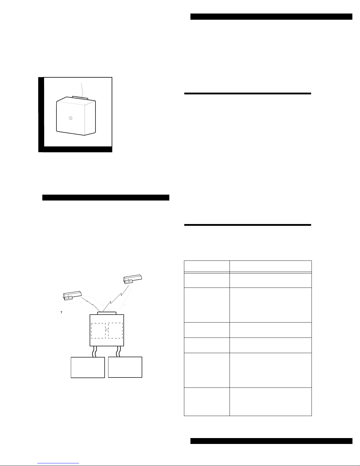
Possible Combinations of Wireless
Devices
The receiver can learn and supervise up to two sen-
sors.
What the Wireless Devices Can Do
Table 2 describes how ITI sensors work with the
receiver. The shaded area represents the low battery
and supervisory transmissions to the supervise relay.
Use this information, together with the panel installa-
tion instructions, to plan the installation of wireless
devices.
Planning the installation
Before you begin programming, it is a good idea to
write down how you plan to use the wireless devices
with each zone. Use Table 3 as a work-sheet.
Table 2. Use the information in the table below to plan your installation
of wireless devices.
This device… When this event happens… Has this effect on the receiver…
PIR motion sensor
(all ITI models) Motion is detected or tamper switch is
tripped Activates the alarm relay for a minimum of 3
seconds
Smoke sensor
(60-506-319.5 only) Smoke is detected (no tamper switch) Activates the alarm relay for a minimum of 3
seconds
Panic sensor
(60-578 only) Panic button is pressed (no tamper
switch on panic sensors) Activates the alarm relay for a minimum of 3
seconds or until the button is released, which-
ever is last
Door/window sensor Opening the door
or tripping the tamper switch Activates the alarm relay for a minimum of 3
seconds or until the door is closed
Closing the door (if door was opened)
or resetting the tamper switch (if tamper
switch was tripped)
De-activates the alarm relay
Any sensor added to the mem-
ory of the receiver Battery is low and/or
sensor is not transmitting
supervisory information
Activates the supervise relay for a mini-
mum of 3 seconds
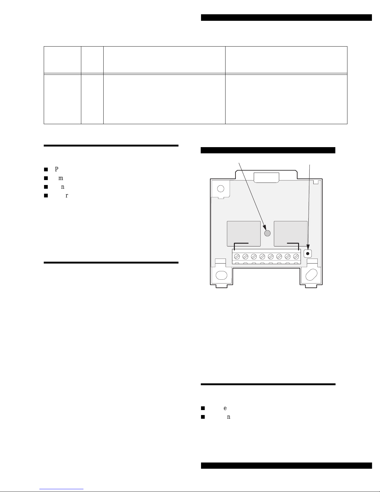
LED will single-flash, double-flash, or
triple-flash every 4 seconds as a trouble
indicator (see “What the states of the
LED mean” on page 1)
Battery is replaced (if the battery
was low) or supervisory transmis-
sions resume (if the sensor was not
transmitting)
De-activates the supervise relay

Page 3
Quik Bridge® Supervised One-Channel Receiver
Sensor Compatibility
The following current ITI Learn Mode™ wireless
devices are compatible with this receiver:
O
PIR motion sensors
O
Smoke sensors (60-506-319.5 only)
O
Panic sensors (60-578 only)
O
Door/window sensors (see note below)
Note: Only the internal reed switches of a door/win-
dow sensor can be used. The receiver does not
support the use of sensors with external devices
connected to the sensor terminal block.
Control Panel Compatibility
The receiver will expand one zone of any conven-
tional hardwired control panel.
Note: The receiver should not be connected to pow-
ered zones (such as 2-wire smoke zones).
Overview of Receiver Operation
Figure 2. Parts of the Receiver
Programming Button
Use the programming button (see Figure 2) when
doing the following procedures:
O
“Deleting All Wireless Devices” on page 6
O
“Adding Wireless Devices” on page 6
Table 3. Zone assignments for wireless devices
Panel
Zone
(supervising)
Panel
Zone
(alarm) Devices Functions
_________________________________________
_________________________________________
_________________________________________
_________________________________________
_________________________________________
_________________________________________
_________________________________________
_________________________________________
9216G 03A .D S F
LED INDICATOR PRO GRAM M ING
BUTTON
TERM INAL STRIP
SUPERVISE RELAY N/O
SUPERVISE RELAY COM M ON
SUPERVISE RELAY N/C
ALARM RELAY N/O
ALARM RELAY CO M M ON
ALARM RELAY N/C
+12 V D C
GROUND
1 2 3 4 5 6 7 8

Page 4
Quik Bridge® Supervised One-Channel Receiver
Zone Outputs
The receiver has eight terminals. Terminals 1 and 2
are for +12 VDC power input. Terminals 3–5 are the
alarm outputs that you connect to the desired panel
zone input. Terminals 6–8 are the supervision outputs
that you connect to the desired panel zone input. The
zones can be configured to be normally closed (N/C)
or normally open (N/O) (see “Connecting the
Receiver to a Control Panel” on page 7).
Tools and Accessories Needed
Included with Receiver
O
Four 1½'' screws
O
Wall anchors
Not Included with Receiver
O
Drill with assorted bits
O
EOL resistors (usually supplied with the panel)
O
Phillips screwdriver
O
Voltmeter
O
Wire stripper
Installation Guidelines
Observe the following guidelines when installing the
receiver:
O
Leave ten inches above the receiver for the
antenna.
O
Avoid areas that are likely to expose the receiver
to moisture.
O
Avoid areas with excessive metal or electrical
wiring, including furnace and utility rooms.
O
Avoid mounting the receiver on a metal surface.
When mounting on metal is unavoidable, mount
the receiver so that the antenna extends above the
metal surface (see Figure 2)
O
The One-Channel Receiver is a super regenera-
tive receiver. To ensure consistent operation of
the receiver, mount it at least three feet away
from other super regenerative receivers (such as
the receiver in most garage door openers).
Figure 3. When mounting on metal is unavoidable
Installation
This section explains how to install the Quik Bridge
Supervised One-Channel Receiver.
Mounting the Receiver
CAUTION: You must be free of static electricity
before handling circuit boards.
Touch a bare metal surface or use a
grounding strap to discharge your-
self.
To mount the receiver on a wall:
1) Choose a location for the receiver. You can
mount the receiver on a sheetrock wall, but you
may need to use additional mounting hardware.
METAL METAL
8836G02A.DSF

Page 5
Quik Bridge® Supervised One-Channel Receiver
2) Remove the cover by pressing down on the center
of the top edge of the cover (see Figure 4).
Figure 4. Removing the cover
3) Hold the receiver against the wall at the desired
height and location, leaving at least ten inches
above the base for the antenna. While holding the
receiver against the wall, mark the location of the
top-left and lower-right mounting holes.
4) Remove the base from the wall and install wall
anchors at any marked location where studs are
not present.
5) Secure the receiver to the wall using two 1½''
Phillips screws (included).
6) Secure the antenna to the wall using a T-18 staple
gun and 9/16” staples.
Powering the Receiver
CAUTION: You must be free of all static elec-
tricity when handling sensors. Touch
a grounded metal object before han-
dling the circuit board.
You must connect the receiver to the +12 VDC power
outputs on the panel or to a separate power supply
(such as 12-volt DC adapter).
Note: If you choose not to connect the receiver to the
panel power outputs, consider using a power
supply with a back-up battery (in case of power
outages).
To find the DC power terminals on the panel, see the
panel installation instructions.
To power the receiver:
1) Shut off or remove power from the panel.
2) Using Figure 5 as a guide, connect the receiver to
the panel or other equivalent power supply.
Figure 5. Connecting power to the receiver
9217G07A.DS
F
9217G02A.DSF
SCREW MOUNTING HOLES
9216G 08A .D S F
PANEL AUXILIARY
PO W ER TERM INALS
O R +12 V D C
PO W ER SUPPLY
RECEIVER POW ER TERMINALS
+12 V D C
GROUND
+12 V D C
GROUND
345678
12

Page 6
Quik Bridge® Supervised One-Channel Receiver
Programming
This section explains how to add and delete wireless
devices from the memory of the Quik Bridge Super-
vised One-Channel Receiver.
Deleting All Wireless Devices
Delete all wireless devices from the memory of the
receiver before you begin adding any new ones.
Deleting all wireless devices clears the memory of the
receiver. This prepares the receiver for new program-
ming.
Note:It is not possible to delete devices one at a time.
To delete all wireless devices from the receiver:
1) Press and hold the programming button. In about
three seconds you will hear and feel a “double-
click” from the receiver. Continue holding the
programming button until you hear a second dou-
ble-click from the receiver (3 seconds) and the
LED shuts off.
2) Release the programming button. The LED will
flash twice, indicating that the receiver memory
is cleared.
Adding Wireless Devices
See “Sensor Compatibility” on page 3 for information
on compatible ITI wireless devices.
To add a wireless device to the receiver:
1) Press and hold the programming button until you
hear and feel a “double-click” from the receiver
(about three seconds), then release the program-
ming button.
2) Wait three seconds. The LED will begin flashing,
indicating the receiver is ready to learn a new
wireless device.
Note: If the LED is not flashing, the receiver is not
ready to learn a device. Always wait until the
LED begins flashing before proceeding to the
next step.
3) Trip the device while holding it at arm length
from the receiver:
For sensors with tamper switches
Activate the tamper switch by removing the
cover.
For sensors without tamper switches
Put the sensor in alarm.
4) After about three seconds, the receiver will dou-
ble-click to indicate that the wireless device was
added.
5) To add another wireless device, go back to step 1.

Page 7
Quik Bridge® Supervised One-Channel Receiver
Connecting the Receiver to a
Control Panel
Connect the receiver zone output terminals to the zone
input terminals on the panel. The receiver zone may
be configured to be N/C (Normally Closed) or N/O
(Normally Open). See figures 6 and 7 for wiring and
EOL resistor placement.
Figure 6. Wiring a receiver zone to be N/C
Testing
This section explains how to test the operation of the
wireless devices that you programmed into the Quik
Bridge Supervised One-Channel Receiver.
General procedure for testing the receiver:
CAUTION: To avoid sending false alarms to the
police or fire department when test-
ing monitored systems, always call
and notify the central station before
activating alarms.
1) For monitored systems, call the central station or
other monitoring service to let them know you
will be testing the system.
2) Arm the panel.
3) Trip a wireless sensor or other device that you
added to the receiver.
4) Restore the sensor to its non-alarm state and dis-
arm the system. Repeat steps 4 and 5 for each
wireless device. Verify that the system goes into
alarm (i.e., sirens activate).
5) If necessary, call the central station and let them
know you have finished testing the system.
Figure 7. Wiring a receiver zone to be N/O
Specifications
Dimensions: 2.5 ×2.6 ×0.9’’(64 ×66 ×23 cm)
Maximum current draw (both relays on): 70 mA
Operating temperature range: 40 to 120°F (4 to 49°C)
Power requirements: 11.5 to 15 VDC
Receiver frequency: 319.5 MHz
Receiver range: 250 feet (76 meters) minimum in
open air
Receiver type: Super regenerative
Relay contact rating:
Current: 7A maximum
Voltage: 250 VAC maximum
Contact: Dry contact Form C
Weight: 2.5 oz., including antenna
9216G 05a.D S F
PANEL
ZO N E
IN P U T S
SUPERVISE RELAY N/O
SUPER VISE RELAY CO M M O N
SUPERVISE RELAY N/C
ALARM RELAY N/O
ALARM RELAY CO M M ON
ALARM RELAY N/C
+12 V D C
GROUND
RECEIVER ZONE
OUTPUT TERM INALS
RETURN
ZO N E 1
+12 V D C
GROUND
RETURN
ZO N E 2
1 2 3 4 5 6 7 8
9216G 07a.D S F
PANEL
ZO N E
IN P U T S
SUPERVISE RELAY N/O
SUPER VISE RELAY CO M M O N
SUPERVISE RELAY N/C
ALARM RELAY N/O
ALARM RELAY CO M M ON
ALARM RELAY N/C
+12 V D C
GROUND
RECEIVER ZONE
OUTPUT TERM INALS
RETURN
ZO N E 1
+12 V D C
GROUND
RETURN
ZO N E 2
1 2 3 4 5 6 7 8

Page 8
Quik Bridge® Supervised One-Channel Receiver
Notices
This device complies with FCC Rules Part 15. Operation is subject to the following two
conditions:
1) This may not cause harmful iinterference.
2) This device must accept any interference that may be received, including interfer-
ence that may cause undesired operation.
Changes or modifications not expressly approved by Interactive Technologies, Inc. can
void the user’s authority to operate the equipment.
ITI and Quik Bridge are registered trademarks of Interactive Technologies, Inc.
651/777-2690
651/779-4890
Table of contents
Other ITI Receiver manuals