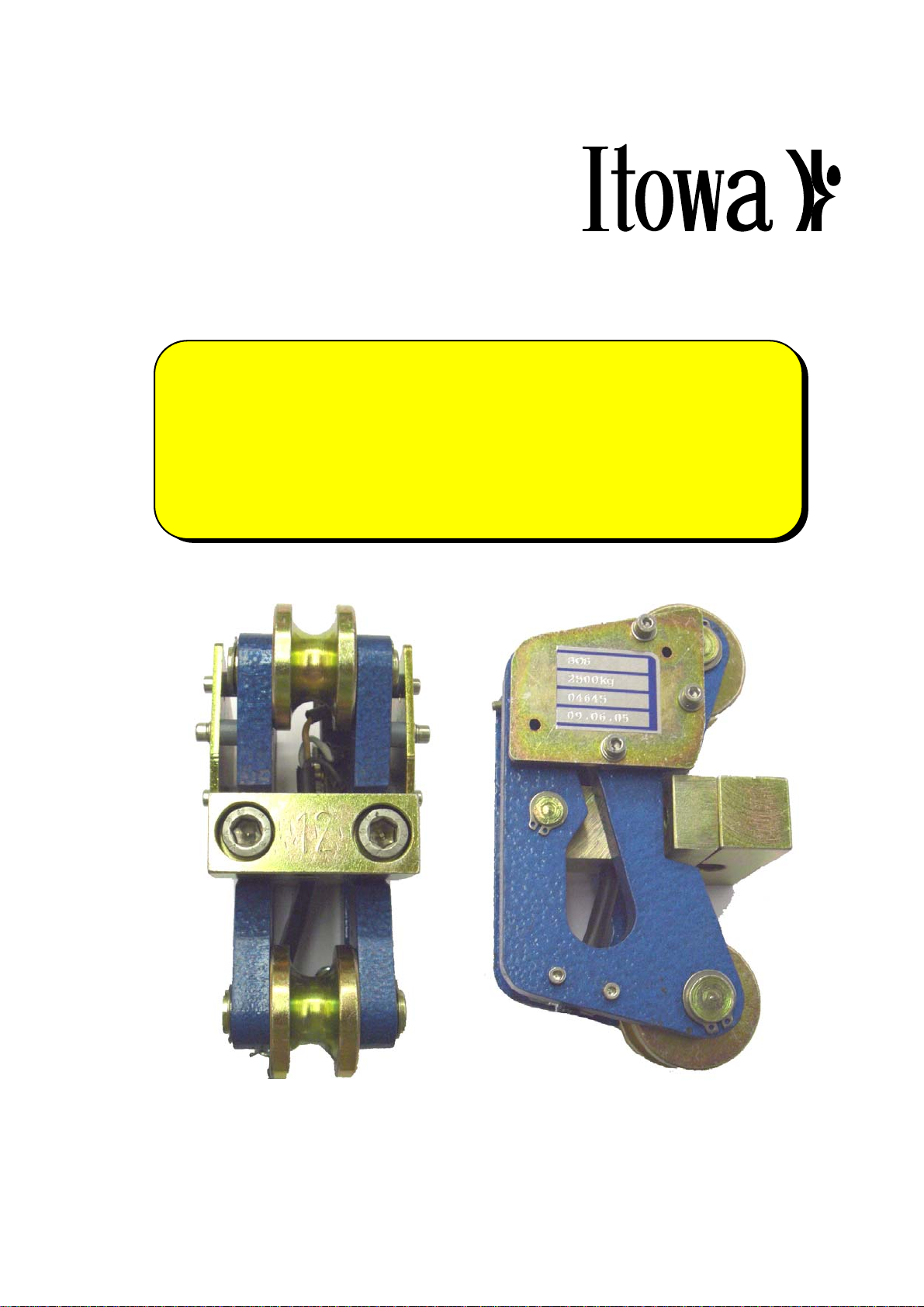
Itowa SW1 User manual

USER’S MANUAL
LOAD LIMITER
SW1


USER’S MANUAL
LOAD LIMITER
SW1
ITOWA S.A.U.
MALIMMC2GB
REV 0
27-07-05
Approved by Engineering Manager: J. Varela
ANY REPRODUCTION, EITHER COMPLETE OR IN PART, OF THIS MANUAL IS STRICTLY
PROHIBITED UNLESS ITOWA HAS GIVEN ITS WRITTEN CONSENT.
OTHERWISE, ITOWA RESERVES THE RIGHT TO INITIATE ALL APROPIATE ACTIONS AS
ESTABLISHED IN LAW
ITOWA RESERVES THE RIGHT TO MODIFY THIS MANUAL WITHOUT PRIOR ADVICE.


LOAD LIMITER SW1
USER’S MANUAL
i
TABLE OF CONTENTS:
1. INTRODUCTION 1-1
2. TECHNICAL DATA 2-1
3. SW1 MODEL 3-1
4. INSTALLATION AND CONNECTIONS 4-1
4.1.1. ASSEMBLING 4-1
4.1.2. INSTALLATION 4-1
4.2. ADJUSTMENT PROCESS 4-1
4.3. CONNECTION 4-3
4.4. CALCULATION OF CABLE TENSION 4-3
APPENDIX
A. USEFUL ADRESSES A-1


LOAD LIMITER SW1
USER’S MANUAL
1-1
1. INTRODUCTION
The SW load limiter has been designed to avoid the overloads, which usually appear in lifter
equipments as tower cranes, travelling cranes, elevators…
It avoids breakage in cables, hooks, wheels, beams and rails distortion, and the rest of damages and
accidents caused by overloading.
The directive 89 / 392 / CEE considers that all of the new cranes must incorporate a load limiter and
the new risk’s prevention law for safety at work remarks the need for suppression of dangerous points,
because the user is responsible for the applied loads, that cannot exceed the maximum allowable
one.
The SW load limiter represents a minimum economic cost in comparison with others electronic load
limitation systems with load cell, that is possible because of its design and low maintenance cost
(pulleys’ lubrication and tare, every 6 months).


LOAD LIMITER SW1
USER’S MANUAL
2-1
2. TECHNICAL DATA
Repeatability: 1 % F.E.
Operation limit temperatures: - 30º C / + 80º C ( -22º F / 176º F)
Overload: 300 % F.E. (F.E. = Crane nominal load)
Output of contacts: 15 A ; 250 Vac
Disconnection limit: 100 % F.E.
Disconnection tolerance: 10 % F.E.
Dimensions: 165 x 95 x 85 mm (67 x 37,5 x 33,5 inches )


LOAD LIMITER SW1
USER’S MANUAL
3-1
3. SW1 MODEL
MOD: SW1 XXXX / YY / Z
XXXX Capacities per cable branch
200, 500, 1000, 1500, 2000, 3000, 4000, 10000 kg
(441, 1102, 2204, 3304, 4409, 6614, 8818, 21980 pounds)
YY Cable diameter
5, 6, 7, 8, 9...25
(0.197, 0.236, 0.276, 0.315, 0.354 … 0.984 inches)
Z Switchgear outputs
single, 1 - double, 2
Please enquire for other specifications


LOAD LIMITER SW1
USER’S MANUAL
4-1
4. INSTALLATION AND CONNECTIONS
4.1.1. ASSEMBLING
The load limiter must be assembled 50 cm (20 inches) down to the end of the fixed crane rope or any
other lifting machine, near the rocker arm or balancing wheel.
You must be careful that any mobile part of the crane couldn’t crash against the load limiter.
4.1.2. INSTALLATION
To place the load limiter you must follow these steps:
• Unscrew the two bolts that holds the clamp and take it off..
• Place the limiter and fix the clamp again, making sure that both bolts are tightened up,
adjusting the cable on the base.
• The chain must be placed up, and fixed on the machinery structure.
4.2. ADJUSTMENT PROCESS
ATTENTION!: ANY CHANGES IN THE INITIAL CONFIGURATION WILL MEAN THE END OF THE
GUARANTEE.
If you need to change the initial configuration, you must follow these steps:
a) Be sure that the selected weight is between the load limiter design limits.
IT WILL BE RECOMMENDED TO PLACE A WEIGHT EQUAL TO THE SELECTED LOAD VALOUR.
b) Unscrew the fixation (1).
50
Fig. 4.1

LOAD LIMITER SW1
USER’S MANUAL
4-2
c) To increase the weight limit, you must turn the limit screw (2) on clockwise way (for drecrease
it, use the opossite way).
d) Once adjusted, you must block it with the fixation screw (1). We recommend sealing it with
some plastic material.
IMPORTANT!: LOAD LIMITERS ARE FITTED FOR A SPECIFIC LOAD AND ROPE DIAMETER,
SELECTED BY THE COSTUMER.
.ATTENTION!: BE INFORMED THAT WITH SOME MOVEMENTS THE LOAD LIMITER CAN GIVE
AN UPPER WEIGHT THAN REAL. TO AVOID THIS ERROR WE RECOMMEND TO
USE A TIME-LAG RELAY.
Fig. 4.2
2
1

LOAD LIMITER SW1
USER’S MANUAL
4-3
4.3. CONNECTION
The load limiter has a switch contact usually closed (NC):
COM : Brown colour NC : Black colour Ground: Blue colour
This contact should activate the crane’s command control.
4.4. CALCULATION OF CABLE TENSION
r : Number of ropes
P : Crane capacity
T : Cable tension (fixed cable)
COM
NC
NO
r
P
T=
2 ROPES


LOAD LIMITER SW1
USER’S MANUAL
A-1
APPENDIX
A. USEFUL ADRESSES
ITOWA S.A.U.
c/ Faraday, 159
08224 TERRASSA (BARCELONA)
Telf.: +34-93.733.98.50
Fax: +34-93.789.13.51
http:://www.itowa.com


DCLIMMCGB – REV. 1
EC - DECLARATION of CONFORMITY
The manufacturer: ITOWA, S.A
C/ Faraday, 159
08224-Terrassa
Barcelona, SPAIN
Tel.: + 34 93 733 98 50
Fax: + 34 93 789 13 51
Declares under its responsibility that the product designated as:
AALIMMEC
Description: Electromechanical load limiter for crane
Is in conformity with the following standards:
EN 12077-2:1998, EN ISO 12100-2:2003 and EN 60204-32:1998
Concerning the safety of machinery (European Directive 98/37/EC)
And with the standards:
EN 61000-6-2:2001 and EN 61000-6-4:2001
Concerning the electromagnetic compatibility (European Directive 89/336/EC)
Signatory: Name: Ramón Faure
Function: Technical Manager
Place and date: Terrassa, March 7th 2005
Signature

Table of contents
Popular Industrial Equipment manuals by other brands

SMC Networks
SMC Networks KF Series Operation manual

Reer
Reer Mosaic MOR4 Quick installation guide

Ronin
Ronin 2805-2000-17 instruction manual

Giebel
Giebel Adsorber Vario VG Assembly and maintenance manual

Cleveland
Cleveland SGY-1000-D Operation manual

Agilent Technologies
Agilent Technologies G5562A Safety and installation guide