iTriangle Infotech Pvt Ltd aQuiLa track User manual

iTriangle Infotech Pvt Ltd
Page
1
o
f
30
Note: Engineering Documents are Highly Confidential
User Manual
OBD-II Dongle V1.1

iTriangle Infotech Pvt Ltd
Page
2
o
f
30
Note: Engineering Documents are Highly Confidential
Description: User manual for OBD-II Dongle Document Name:
OBDII_Dongle_User_Manual_V1.1
REVISION HISTORY
S.
NO
REV.
NO DATE CHANGE DESCRIPTION Revised By
1 1.0 20-09-
2017 First Version NA
2 1.1 09-11-
2017 Added the battery connection in section 9 Nikhil B
3 1.2
PREPARED BY VERIFIED BY APPROVED BY
Nikhil B Pavan N Kiran A R

iTriangle Infotech Pvt Ltd
Page
3
o
f
30
Note: Engineering Documents are Highly Confidential
Contents
1 Introduction .................................................................................................................................... 6
1.1 Instructions of safety .............................................................................................................. 6
1.2 Copyright Notice ..................................................................................................................... 6
2 Overview of document ................................................................................................................... 6
3 Basic Description ............................................................................................................................. 6
3.1 Contents of the package ......................................................................................................... 7
3.1.1 3.1.1 The package contains: ............................................................................................ 7
3.2 Basic Characteristics ................................................................................................................ 7
3.2.1 GSM/GPRS .............................................................................................................................. 7
3.2.2 GPS Module:........................................................................................................................... 7
3.2.3 Hardware features: ......................................................................................................... 7
3.2.4 USB Interface features: ................................................................................................... 7
3.2.5 Record Storage/Buffer: ................................................................................................... 8
3.2.6 Operating Condition:....................................................................................................... 8
3.2.7 Firmware Features .......................................................................................................... 8
3.2.8 Mechanical Details .......................................................................................................... 8
4 Technical Information about internal Battery: ............................................................................... 8
4.1.1 Battery Disposal Instruction: ........................................................................................... 8
5 Mechanical Overlay......................................................................................................................... 8
6 LED Indications .............................................................................................................................. 10
6.1 OBD ....................................................................................................................................... 10
6.2 GPS LED (Blue ) ................................................................................................................. 10
6.3 Process LED (Red ) ............................................................................................................ 10
6.4 GSM LED (Green ) ............................................................................................................ 10
7 Configuration ................................................................................................................................ 11
7.1 System requirements ............................................................................................................ 11
7.2 Setup Java Environment........................................................................................................ 11
7.2.1 Installation of JDK.......................................................................................................... 11
7.2.2 Setting environmental variables ................................................................................... 13
8 Configuration ................................................................................................................................ 16
8.1 SMS command ...................................................................................................................... 16
8.2 GPRS Command .................................................................................................................... 16

iTriangle Infotech Pvt Ltd
Page
4
o
f
30
Note: Engineering Documents are Highly Confidential
8.3 Device configuration tool ...................................................................................................... 16
8.3.1 Landing Page: ................................................................................................................ 17
8.3.2 Communication Parameters ......................................................................................... 18
8.3.3 Transmission Parameters .............................................................................................. 18
8.3.4 Eco Driving .................................................................................................................... 19
8.3.5 Miscellaneous: .............................................................................................................. 20
8.3.6 PID settings: .................................................................................................................. 21
8.3.7 Write to Flash: ............................................................................................................... 22
8.4 Commands ............................................................................................................................ 22
8.4.1 Configuration Commands ............................................................................................. 22
8.4.2 Diagnostic Commands................................................................................................... 24
8.4.3 Getter commands ......................................................................................................... 25
8.4.4 Control Commands ....................................................................................................... 26
9 Installation .................................................................................................................................... 27
9.1 General Prerequisite ............................................................................................................. 27
9.2 Inserting the Battery connector ............................................................................................ 27
9.3 SIM Card Insertion Scheme ................................................................................................... 27
9.4 Installation Location in the vehicles ...................................................................................... 28
10 Troubleshooting ........................................................................................................................ 28
10.1 Trouble shooting steps .......................................................................................................... 28
11 Do’s & Don’ts ............................................................................................................................ 29
11.1 Do’s ....................................................................................................................................... 29
11.2 Don’ts .................................................................................................................................... 29
12 FAQ (Frequently Asked Question) ............................................................................................ 29
Table of Figures
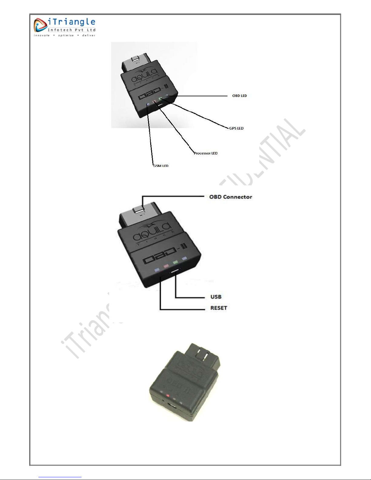
Figure 1: LED Indicators .......................................................................................................................... 9
Figure 2: Interfaces ................................................................................................................................. 9
Figure 3: LED Blinking .............................................................................................................................. 9
Figure 4: OBDII extension cable ............................................................................................................ 10
Figure 5: JDK Installation step 2 ............................................................................................................ 11
Figure 6: JDK Installation step 3 ............................................................................................................ 12
Figure 7: JDK installation step 4 ............................................................................................................ 12
Figure 8: JDK Installation step 5 ............................................................................................................ 13
Figure 9: JDK installation step 6 ............................................................................................................ 13

iTriangle Infotech Pvt Ltd
Page
5
o
f
30
Note: Engineering Documents are Highly Confidential
Figure 10: System Properties ................................................................................................................ 14
Figure 11: Environmental variables ...................................................................................................... 14
Figure 12: Setup System variables ........................................................................................................ 15
Figure 13: Edit Environmental variables ............................................................................................... 16
Figure 14: Landing Page ........................................................................................................................ 17
Figure 15: Menu population ................................................................................................................. 17
Figure 16: Communication parameters ................................................................................................ 18
Figure 17: Transmission parameters ..................................................................................................... 19
Figure 18: Eco Driving ........................................................................................................................... 20
Figure 19: Miscellaneous ...................................................................................................................... 21
Figure 20: PID settings .......................................................................................................................... 21
Figure 21: Installation of the battery .................................................................................................... 27
Figure 22: SIM card not inserted........................................................................................................... 28
Figure 23: SIM card inserted ................................................................................................................. 28

iTriangle Infotech Pvt Ltd
Page
6
o
f
30
Note: Engineering Documents are Highly Confidential
1 Introduction
1.1 Instructions of safety
This chapter contains information on how to operate aQuiLa OBD ll Dongle safely. By following these
requirements and recommendations, you will avoid risky situations. Please read the instructions
carefully and follow them strictly while operating the device.
aQuiLa track OBD ll dongle is designed to work in automotive environment with supply range
of +9V to +32V DC power supply.
To avoid mechanical damage, it is advised to transport the aQuiLa OBD ll dongle in an impact
proof package.
Device should be installed in the OBD connector in a vehicle, which already exists in the
Vehicle.
1.2 Copyright Notice
The information disclosed here is the exclusive property of iTriangle Infotech Pvt ltd and no part
of this document can be reproduced or transmitted in any form or by means including electronic
storage, reproduction, or execution without the prior written permission from iTriangle Infotech Pvt
Ltd. The information contained in this document is subjected to change without notice and should not
be construed as a commitment by iTriangle Infotech Pvt Ltd unless such commitment is expressly given
in a separate document.
ITriangle Infotech Pvt Ltd © copyright notice and statement that, “No Part of this document may be
reproduced without the prior written consent of iTriangle Infotech Pvt Ltd”.
2 Overview of document
This manual covers the various features of OBD ll Dongle and information about the terminologies,
possibilities, electrical, mechanical characteristics, & configuration of the OBD-II Dongle.
PC
Perso
nal Computer
GPRS
General Packet Radio Service.
GSM
Global System for Mobile Communication.
GPS
Global Positioning System
SMS
Short Messa
ge Service
AC/DC
Alternating Current/Direct Current
I/O Input /Output
GNSS Global Navigation Satellite System
CAN Controller Area Network
K-line Keyword Protocol -2000
Table 1:Acronym
3 Basic Description
The on-Board Diagnostics system is composed of a computer that monitors the emissions system
and key engine components. It can usually detect a malfunction or deterioration in these
components before the driver becomes aware of the problem.

iTriangle Infotech Pvt Ltd
Page
7
o
f
30
Note: Engineering Documents are Highly Confidential
OBD systems are designed to alert the driver when a component in the engine management or
emissions systems begins to deteriorate or malfunction. Early detection of minor problems, followed
by timely repair, can often prevent more costly damage to components such as the catalytic
converter.
OBD ll is an electronic device which locates its position, PIDs, DTC and sends it by using GPRS
network. This device is suitable for applications, where it needs the location of remote vehicle and
vehicle health check-up’s.
3.1 Contents of the package
Usually the OBD ll dongle is supplied to the customer in a cardboard box containing all the
equipment that is necessary for operation.
3.1.1 3.1.1 The package contains:
Unsealed One- piece OBD ll dongle.
OBD ll Connector Cable – Length 1 Meter
Warranty card
3.2 Basic Characteristics
3.2.1 GSM/GPRS
Quad - Band GSM 850/900/1800/1900 MHz
GPRS: Class 10 Coding Scheme CS1 (1W @ 1800/1900MHz) to CS4 (2W @ 850/900MHz)
SMS (text).
GPRS multi-slot class 12/10
3.2.2 GPS Module:
GPS: 66 search channel acquisition -/22 simultaneous tracking channels.
Tracking Sensitivity: -165dBm, inbuilt patch antenna.
5 Meters Accuracy @ -130 dBm.
Hot Starts: < 1 s
Cold Starts; -147dBm
Cold Starts: 31 s [Typical]
Warm Starts: 30 s
3.2.3 Hardware features:
MT6260 Chipset
8 MB Solid State Flash, 100K Erase and Program Cycle, 10 Year data retention
Motion Sensor - 3 Axis accelerometer
Internal backup battery
Supports SIM card: 1.8V and 3V Micro SIM
3.2.4 USB Interface features:
Wide DC Input Voltage Range [9V – 32V]
CAN
K-Line [KWP]
LEDs Indicating device status

iTriangle Infotech Pvt Ltd
Page
8
o
f
30
Note: Engineering Documents are Highly Confidential
3.2.5 Record Storage/Buffer:
Up to 10000 tracking records [May vary based on configuration and parameter chosen]
3.2.6 Operating Condition:
Operating temperature : -10 °C to +60°C
Storage temperature :- 10°C to +85°C [Without Battery]
Humidity: 95% Non-condensing
3.2.7 Firmware Features
Detect Harsh Breaking, Harsh Acceleration [Speed Based]
Firmware upgrade over the air Available [ FOTA ]
Data acquisition – Heading & time based
Maintenance server
Sleep Mode
3.2.8 Mechanical Details
Dimensions (mm X mm X mm) -- 55 X 53 X 30
Weight -- 120 Gram
Enclosure -- 30% Glass Filled PA6 Casing
4 Technical Information about internal Battery:
Li-Ion Rechargeable battery, 3.7V, 500mAh
OBD ll operating time with internal backup battery depends on temperature, data sending frequency
(SMS and GPRS) and accumulator age, number of charge/discharge cycle.
Charging temperature : 0 – 45°C
CAUTION: RISK OF EXPLOSION IF BATTERY IS REPLACED BY AN INCORRECT TYPE.
4.1.1 Battery Disposal Instruction:
Battery should not be disposed with house hold waste. Damaged batteries are disposed
to battery recycle bin found in stores
5 Mechanical Overlay

iTriangle Infotech Pvt Ltd
Page
9
o
f
30
Note: Engineering Documents are Highly Confidential
Figure 1: LED Indicators
Figure 2: Interfaces
Figure 3: LED Blinking

iTriangle Infotech Pvt Ltd
Page
10
o
f
30
Note: Engineering Documents are Highly Confidential
Figure 4: OBDII extension cable
6 LED Indications
6.1 OBD
Behaviour Meaning
Continuously Blinking Communication with OBD
Continuously OFF No communication with OBD
Table 2: OBD LED behaviour
6.2 GPS LED (Blue )
Behaviour
Meaning
Permanently Switched OFF
GPS signal is not received
Blinking Every Second
Normal Mode, GPS is working
Table 3: GPS LED behaviour
6.3 Process LED (Red )
Behaviour Meaning
Blinking Every Second
Normal Mode
LED is in OFF State
Sleep Mode / Device is not working
Table 4: Process LED behaviour
6.4 GSM LED (Green )
Behaviour
Meaning
Blinking Every one Second
Before SIM Register
Blinking fast constantly
After SIM Register
LED is OFF
Device is in Sleep Mode
Table 5: GSM LED behaviour

iTriangle Infotech Pvt Ltd
Page
11
o
f
30
Note: Engineering Documents are Highly Confidential
7
Configuration
7.1 System requirements
Operating system version: 32-bit and 64-bit.
Operating system: Windows 7 and later.
Java: JDK and JRE 8.0 and above.
Download PL2303 & MTK driver and install them, download the USB driver from below link
https://www.itriangle.in/aquila-hardware-board-diagnostics-obd-ii/
7.2 Setup Java Environment
7.2.1 Installation of JDK
Download and follow below procedure for installing jdk 1.8. Download the appropriate jdk
(32bit/64bit) based on the system which it is intended to use.
http://www.oracle.com/technetwork/java/javase/downloads/jdk8-downloads-2133151.html
Select and open the downloaded file.
Pop up message will come by requesting Yes or No. select Yes.
Below mentioned window will appear.
Figure 5: JDK Installation step 2
Then select Next, it goes to next step.

iTriangle Infotech Pvt Ltd
Page
12
o
f
30
Note: Engineering Documents are Highly Confidential
Figure 6: JDK Installation step 3
Again, select to proceed further, wait till the process completes.
Figure 7: JDK installation step 4
Destination folder interface will be displayed, click on next.

iTriangle Infotech Pvt Ltd
Page
13
o
f
30
Note: Engineering Documents are Highly Confidential
Figure 8: JDK Installation step 5
In the final step, click on close.
Figure 9: JDK installation step 6
7.2.2 Setting environmental variables
Copy the bin folder path from the folder in which the Java is installed. Below is the example
path.

iTriangle Infotech Pvt Ltd
Page
14
o
f
30
Note: Engineering Documents are Highly Confidential
C:\Program Files\Java\jdk1.8.0_141\bin
Right click on My Computer/This PC icon in your system and click on properties.
Figure 10: System Properties
Select Advanced System settings in the System window. (For windows 10)
In system properties window, click on “Environmental Variables”
Figure 11: Environmental variables

iTriangle Infotech Pvt Ltd
Page
15
o
f
30
Note: Engineering Documents are Highly Confidential
In system variable window of wage Environmental Variables, paste the java path which is copied
in the value of the variable “Path”.
Figure 12: Setup System variables

iTriangle Infotech Pvt Ltd
Page
16
o
f
30
Note: Engineering Documents are Highly Confidential
Figure 13: Edit Environmental variables
8 Configuration
8.1 SMS command
SMS command should be sent to the device mobile number to update the firmware. Once the FOTA
is completed Admin 2 number will get the FOTA status. Below is the SMS command format to
upgrade the firmware over the Air.
Syntax: set$<serial_no>@<device_password>#INIT_FOTA:<FTP_server_address>,<FTP
port>,<FTP_username>,<FTP_password>,<path>,<upgrade_filename>,1234*
8.2 GPRS Command
GPRS command must be sent to the device over the communication channel with prefix “#”. Once
the FOTA is completed, Admin 2 number will receive a confirmation SMS. Below is the GPRS
command format to upgrade the firmware over the Air.
Syntax: #set$<serial_no>@<device_password>#INIT_FOTA:<FTP_server_address>,<FTP
port>,<FTP_username>,<FTP_password>,<path>,<upgrade_filename>,1234*
8.3 Device configuration tool
The Device configuration tool (DCT) is the tool to configure the device with different configuration
parameters.
Connect the device to the PC via USB and open the configuration tool.
Once the configuration tool is opened, it will direct to landing page

iTriangle Infotech Pvt Ltd
Page
17
o
f
30
Note: Engineering Documents are Highly Confidential
8.3.1 Landing Page:
The image shows the options present on the landing page.
Figure 14: Landing Page
Select Com: - The tool automatically detects the appropriate COM port where the device is
connected to. In case the port is not automatically detected, please restart the tool.
Select model: - Please select the appropriate device model.
Once selected, the device model the parameters menu will be displayed.
Figure 15: Menu population
By default, all the columns in parameters menu will display as blank.
Device Password: - Enter the device password once Model, port was selected.

iTriangle Infotech Pvt Ltd
Page
18
o
f
30
Note: Engineering Documents are Highly Confidential
Connect: - After the password has been rightly entered, click on the “Connect” button.
Proceeding further, device statistics like Firmware Version, Serial number and IMEI will be
displayed.
Disconnect: -This option is to be used to disconnect the device after the configuration has been
completed successfully.
Change Password: -This option is used to change the password of the device.
Load from flash: - This option displays the default settings which are currently configured in the
device.
Save to file: - The settings present in the device can be saved/exported to a “.txt” file by using
this option. The saved settings are non-editable by the user.
Load from file: - The previously saved settings files can be re-loaded by using the “Load from
file” option.
8.3.2 Communication Parameters
Communication parameters column contains the below points to configure.
IP Address/Domain: - This option is used to configure the IP of server to which data must send.
Port: - The port number to be configured must be input in this field.
Client ID: - This prefers to configure client ID. It is combination of alpha-numeric and single
underscore.
APN: - This option is meant for configuring the Access Point Name. It can be alpha-numeric and
must be in range of 1-30 characters.
Figure 16: Communication parameters
8.3.3 Transmission Parameters
In general, the data will be sent from device in 2-time intervals. Those intervals can be configured in
two conditions When Ignition is ON and When Ignition is OFF.

iTriangle Infotech Pvt Ltd
Page
19
o
f
30
Note: Engineering Documents are Highly Confidential
Ignition ON: - This option is used to configure the interval for data transmission from device
when the ignition is in ON condition. The range lies in between 10 to 600 seconds
Ignition OFF: - This selection is used to configure the interval for data transmission from device
when the ignition is in OFF condition. The range is between 01 to 60 mins.
Apart from the Ignition ON and OFF time intervals, there is another optional setting – “Angle Polling”.
Clicking the checkbox will configure the setting in the device else will be omitted.
Angle polling: - This option is used to configure Angle polling; it will be in form of degrees. It lies in
between 30 to 120 degrees.
Figure 17: Transmission parameters
8.3.4 Eco Driving
It consists of parameters which are observed at the time of driving.
HA Threshold: - The Harsh Acceleration threshold value is the value which must be set in the device
in Kmph/sec. If the vehicle crosses this threshold, an alert will be generated stating Harsh
Acceleration. The typical range is from 5kmph/s – 120kmph/s.
HB Threshold: - The Harsh Braking threshold value is the value which must be set in the device in
Kmph/sec. If the vehicle crosses this threshold, an alert will be generated stating Harsh Braking. The
typical range is from 5kmph/s – 120kmph/s.
HC Threshold: - The Harsh Curving threshold value is the value which must be set in the device in
Kmph/sec. If the vehicle crosses this threshold, an alert will be generated stating harsh curving. The
typical range is from 5kmph/s – 120kmph/s.
Over Speed Threshold: - The name in the sense represents that it will detect over speed case. It is
configured by using over speed threshold. It lies in between 5 to 255 Kmph.
Over Speed Duration: - The duration is used to detect over speed condition if the vehicle
continuously moves with over speed configured for the given duration, it is configured by using this
option. In general, it is in range of 5 to 60 Secs.

iTriangle Infotech Pvt Ltd
Page
20
o
f
30
Note: Engineering Documents are Highly Confidential
Figure 18: Eco Driving
If the checkbox present near the column is checked, then the setting will be configured else will be
omitted.
8.3.5 Miscellaneous:
TOF: - This is used to set the GMT offset in the device. The offset should be entered in seconds.
Ex: +5.30hrs must be entered as 19800 seconds.
Admin Mob1 & Admin Mob2: This option is used to configure admin mobile numbers, default it
starts with +91
IMEI/Serial Number: - This selection indicates the selection of IMEI or Serial number in the
tracking data packet.
Set Odometer: This setting feature is used to pre-set the Odometer value.
Compress BF: To enable Compress BF the checkbox near it must be checked.
Table of contents