PS200 Configuration & Operation Guide
GETTING STARTED
Page 3
GETTING STARTED
How to use this guide
This guide has been organized to make setting-up and
configuration of the PumpSmart PS200 easy. Set-up has been
divided into three main sections that include all the
information needed to get up-and-running. The three
sections are:
xSingle Pump - Where one pump is used with a single
process instrument to control on pressure, flow, level, or
temperature.
xMulti-Pump - Where several pumps are used in a
coordinated fashion to meet a pressure, flow, level, or
temperature setpoint.
xSpeed Control - Where a speed setpoint or signal is used
to control PumpSmart.
Each section has been laid out to speed you through the
configuration process, while providing enough background
information to help understand the process.
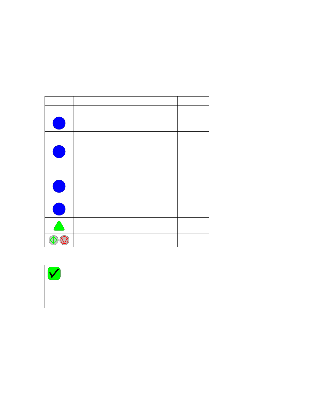
1. Step Number - The step number helps to keep track of
where you are in the configuration process when used in
conjunction with the process map.
2. Process Map - The process map is a visual guide of what
needs to be done in the step.
3. Background Information - This information explains what
the upcoming steps are and why they are being
performed. Examples are provided to assist in
understanding the concept.
4. Special Notes - These highlighted sections contain
comments that are important to the configuration
process.
5. Key Step - The key step box details the actual parameter
that must be entered into PumpSmart. It includes the
basic keys necessary to input the information.
6. Keypad View - The keypad view shows what you will see
as you perform the configuration outlined in the Key
Step.
Following the initial configuration steps, are sections related
to tuning the PumpSmart PS200 once its running, enabling
additional options and features, and troubleshooting if you
are having problems.
2
Motor Setup
The PumpSmart PS200 variable frequency drive utilizes
Direct Torque Control [DTC] rather than a scalar speed
control variable such as Volts/Hertz. Direct Torque
Control provides more precise speed control, hence
more responsive and accurate control to your set point.
Specific motor data must be ente red into the
PumpSmart drive to enable it to properly control the
motor using DTC.
Steps to be performed are:
1. Enteri ng motor data for characterization
2. Identification of the Motor starting method
3. Establishment of the Maximum and Minimum
speed limits
MOTOR DATA
The motor data will allow the PumpSmart drive to
characterize the motor during its first start-up. During
characterization, PumpSmart will automatically magnetize
the motor windings for 20Æ60 seconds to develo p a
mathematical model of the motor. Entry of the foll owing
parameters is all that is required.
NOTE - If the motor is changed in the future, this data must
be re-entered and a new characterization performed.
NOTE - The information required for this section can be
found on the motor nameplate.
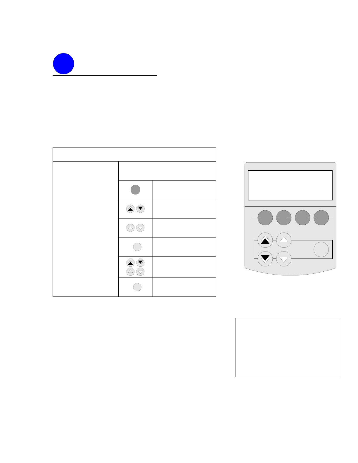
11.04 MOTOR NOM VOLTAGE
KEY SEQUENCE
[From parameter group: 10-
LOCKS/PASSWORDS]
OR
Scroll to parameter group
11
OR
Scroll to parameter 11.04
“MOTOR NOM VOLTAGE”
ENTER
Press to enter the
parameter setting mode
OR
OR
Use a combination of the
arrow keys to scroll to the
nameplate motor voltage.
Enter the value for the
voltage as it appears on
the motor na meplate.
Most commo n voltages
are:
380
460
575
ENTER
Press to complete the
entry
ACT PAR FUNC DRIVE
ENTER
1 L Æ100 GP M 0
11 START-UP DATA
4 MOTOR NOM VOLTAGE
460
!
Motor Data
Maximum
Minimum Speeds
Start/Stop
Method
2
1
3
4
Key Step
Background
Information
Special Notes
Step Number
Keypad View
Process Map
Figure A - Typical Configuration Page
Language Selection
The PumpSmart PS200 drive display
supports the following languages:
English
English (American) - Default
French (Francais)
German (Deutsch)
Italian (Italiano)
Portuguese
Spanish (Espanol)
Language selection may be
performed using parameter 11.01
LANGUAGE, see OPTIONS &
FEATURES for further details.