ITW Trans Tech Orion 130 User manual

Technical Services
Orion 130 Ver. 2
Dec 2017 and up (PLC programs 2_17 and up)
(Elc. Drawing 9211-80-001-F and up)
Operator’s
Manual
ITW Trans Tech: Complete Pad Printing Solutions

Orion 130 v2
For best results when printing this file, set printer resolution to 300 dpi.
While every effort has been made to ensure the accuracy
of this manual, Trans Tech cannot be held responsible for
any errors or omissions. We reserve the right to make
changes to technical specifications without prior notice.
Revised July 2009
Page 2
Trusted Partner for Your Product Decorating Needs
Trans Tech 475 North Gary Avenue, Carol Stream, IL 60188
Tel +1 (630) 752 4000 Fax +1 (630) 752 4467
Email [email protected]
www.itwtranstech.com www.itwids.com
A MEMBER OF

Orion 130 v2
Contents
1. Safety ..................................................................................................................4
1.1. Symbols and their Interpretations .........................................................4
1.2. Liability ...............................................................................................4
1.3. General Warnings and Cautions ..........................................................4
1.4. Application Restrictions .......................................................................4
2. Installation Instructions .....................................................................................5
2.1. Warnings and Cautions .......................................................................5
2.2. Selecting the Location .........................................................................5
2.3. Leveling the Machine ..........................................................................5
2.4. Connecting to Power ...........................................................................6
2.5. Connecting to Air Supply .....................................................................6
2.6. Setting Pressure Regulator ..................................................................6
3. Operating Controls ............................................................................................7
3.1. Front Panel Controls ...........................................................................7
3.2. Left Side Controls ...............................................................................7
3.3. Operating Control Functions ............................................................... 8
3.4. The Screen Map .................................................................................9
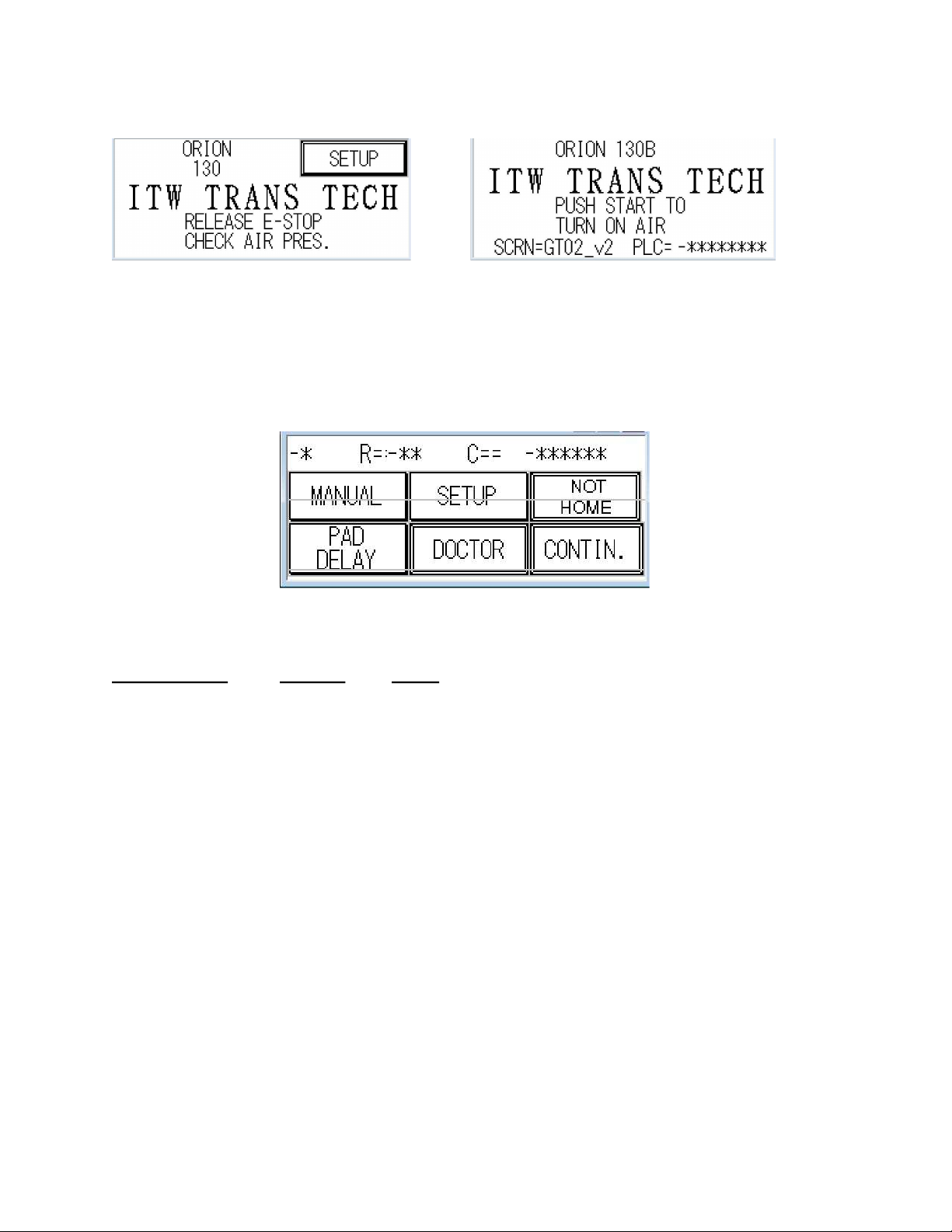
3.4.1. Boot Up Control and Automatic Screen ............................................... 10
3.4.2. Manual Mode ................................................................................. 10
3.4.3. Setup Screen ................................................................................. 11
3.4.11. Accessories ................................................................................. 15
4. Operation ............................................................................................................19
4.1. Startup. ........................................................................................... 19
4.2. Preparing to Print .............................................................................. 20
4.2.1. Mounting the pad ............................................................................ 20
4.2.2. Work support knee .......................................................................... 20
4.2.3. Flow controls ................................................................................. 21
4.2.4. Pad stroke..................................................................................... 21
4.2.5. Assembling the ink cup and cliché ...................................................... 22
4.2.6. Dismanteling the ink cup and cliché .................................................... 23
5. Guidelines for Operating the Machine............................................................ 24
6. Options ................................................................................................................ 25
7. Cliché sizes .........................................................................................................26
8. Cup size changeover .........................................................................................27
9. Technical Information ........................................................................................28
9.1. Machine Specifications ........................................................................28
9.2. Machine Dimensions ...........................................................................29
10. Maintenance ......................................................................................................30
10.1. Wire Termination ...............................................................................30
10.2. Lubrication Schedule ..........................................................................30
10.3. Preventative Maintenance Schedule....................................................31
10.4. Troubleshooting Guide .......................................................................32
10.5. Fault Messages .................................................................................33
10.6.Electrical Schematics. .........................................................................34
10.7 Pneumatic Diagram.............................................................................36
Page 3

Orion 130 v2
1. Safety
1.1. Symbols and their Interpretations
WARNING: Neglecting a safety instruction identified with the WARNING
symbol may lead to personal injury.
CAUTION: Neglecting a safety instruction identified with the CAUTION
symbol may lead to property damage.
POINTER: It is strongly recommended to observe instructions identified with
a POINTER symbol.
1.2. Liability
• In no event will ITW Trans Tech be responsible or liable for indirect
or consequential damages resulting from the use of this
equipment.
• The information contained in this manual is subject to change due to
improvements in design.
• Though this document has been checked for inaccuracies, ITW Trans
Tech does not assume responsibility for any errors contained herein.
• This manual is provided as an aid when operating the Orion 130 pad
printing machine. Prior to operation, it is strongly advised that the user be
thoroughly familiar with the Orion 130 operating manual.
•ITW Trans Tech is not responsible or liable for any disadvantage
occurred for not following the operating instructions.
•All operators must be adequately trained.
1.3. General Warnings and Cautions
• Switch off main disconnect switch (see page 6) prior to connecting/disconnect-
ing power.
•Disconnect the air supply prior to servicing the machine.
1.4. Application Restrictions
• Any use other than described in this manual may cause damage to the equip-
ment, personal injury, or property damage.
Page 4

Orion 130 v2
2. Installation Instructions
2.1. Warnings and Cautions
The machine operates on 100-240 volts, single phase AC power.
Some options such as an Electronic Shuttle require the use of 115VAC.
Switch off main disconnect switch prior to connecting power and air.
Be alert and verify that safe start-up conditions exist prior to connecting the air
supply and switching on the main disconnect switch as the machine may move
when air pressure is applied.
Check the water trap as per connected system water accumulation dictates and
drain as required by pressing the drain valve (see 2.5).
Apply oil or a thin layer of grease to unprotected ferrous parts to prevent
rusting, especially after cleaning with solvents.
2.2. Selecting the Location
Choose a well-ventilated area away from direct sunlight to install your pad printing machine. The ideal
conditions for the inks used in pad printing are approximately 20° C (68° F) and 40 - 60 % humidity.
Make sure the machine is positioned away from walls and other obstructions and placed on a flat
surface. The guards, operating panel and other machine openings must be accessible. Ensure
adequate area for setup tooling and for storage of parts before and after printing.
2.3. Leveling the Machine
Before operation, the machine must be leveled. The level of the machine is adjusted by four (4) feet,
one at each corner of the machine base.
Level the machine as follows:
1. Loosen upper jam nuts.
2. Place bubble levels on machine base, one parallel to the long side of the base and
another parallel to the short side of the base.
3. Adjust bottom nuts on left front and left rear screws until bubble level on the long side reads
level. It may be necessary to ‘follow’ with the right rear to keep machine stable if big
adjustments are required.
4. Adjust bottom nuts equally on right and left rear screws until bubble level on the short side
reads level.
5. It may be necessary to repeat steps 3 and 4 several times until both levels read level and
the weight is evenly distributed on the four feet.
6. Turn the upper jam nuts clockwise to tighten.
Page 5

Orion 130 v2
2.4 Connection to power
The machine is equipped with a power cable ending in
a Nema 5-15 plug.
Power requirement:
♦120 VAC
40 watts
A 230VAC single phase power cord can also be used.
Main disconnect switch
Power cord receptacle
2.5 Connection to air supply
The machine requires clean, dry air.
Minimum requirement:
6 bar (85 psi)
5 cfm
Air connection is to a quick disconnect adapter
(included) or to 3/8” NPT female thread.
Connection for air supply
Adjusting knob
Connection for air supply
Pressure gauge
Bowl with filter inside
Drain valve for water trap
2.6 Air pressure regulator
Adjust system pressure to 6 bar (85 psi) by lifting the
adjusting knob to unlock, then turning the knob clockwise
to increase the pressure or counterclockwise to decrease
the pressure. Push down on the adjusting knob to lock the
regulator after making adjustments.
Page 6

Orion 130 v2
3 Operating Controls
3.1 Front Panel
Emergency
Cycle Start Cycle Stop Stop
Pad Slide Stop
Adjustment
3.2 Left Side
Flow Controls
Pad Ram
Page 7
Touchsc
reen

Orion 130 v2
3.3. The Operating Control Functions
Button
Description
Result
-Active after main disconnect is · Initiate main air valve
Cycle Start
switched ON and E-STOP is cleared. · Start printing cycle
-Lamp is illuminated when power is on.
-Lamp is illuminated when printer is in · Stop printing cycle
Cycle Stop
HOME position. Printer motion will not stop immediately.
-Lamp flashes when an error condition The printer will complete the active print
exists. cycle and stop in the HOME position.
· Interrupts power to inputs and outputs.
E-Stop -Press to activate. · Machine motion is immediately halted.
-Pull to release. The machine may continue to move for a
short distance after E-STOP is pressed.
Touch Screen
-Active after E-Stop is reset. · All setup, operating mode and manual functions
are input via the touch screen.
· Loosen M8 lock screw before making adjustment.
⇒
Turn knurled screw clockwise to move
Pad slide
-Adjust the position of the image on
⇒
image toward printer.
stop - front
the part in the Y direction.
Turn knurled screw counterclockwise to
(see page 7)
move image away from printer.
· Tighten m8 lock screw after making adjustment.
· Loosen lock screw before making adjustment.
Pad stroke
⇒
-
Adjust the pad down stroke limit over
Move slide up to shorten stroke.
down limit
-
⇒
the part.
(see page 7)
Move slide down to lengthen
stroke.
part
· Tighten lock screw after making adjustment.
· Loosen lock screw before making adjustment.
⇒
Move slide up to shorten stroke.
⇒
Pad stroke
Move slide down to lengthen stroke.
-Adjust the pad down stroke limit over
down limit -
· Tighten lock screw after making adjustment.
the cliché.
cliché
· The pad cleaner stroke limit is adjusted at the
(see page 7)
same time as the pad stroke down limit over the
cliché. It can not be adjusted separately.
· Loosen lock ring before making adjustment.
⇒
Turn knurled screw clockwise to slow down
Flow controls
-Adjust the speed of the pad ram.
⇒
movement.
-Adjust the speed of the pad slide. Turn knurled screw counterclockwise to
(see page 7)
speed up movement.
· Tighten lock ring after making adjustment.
· When in single cycle mode, pressing the foot
pedal or the START button will start a print cycle.
· When in continuous cycle mode, pressing the foot
Foot Pedal
Stop and start the printer.
pedal once or pressing the START button will start
a print cycle. Pressing the foot pedal again will
stop the printer at the end of the active step of the
(see page 7)
print cycle. Press again to continue the print cycle.
Page 8

Orion 130 v2
3.4 SCREEN
MAP
TRANS TECH BOOT UP
RELEASE EMERGENCY STOP
PUSH START FOR MAIN AIR ON
AUTO SCREEN
DOCTOR
CONTINUOUS
HOME
MANUAL
SETUP
PAD DELAY
MANUAL
SETUP CHOICE
PAD DELAY
JOG
PRINTER SET
UP
FRONT DELAY=
JOG DOWN
INPUTS/OUTPUTS
REAR DELAY=
JOG X OUTPUT
CUP HLDER UP
PULL TAPE
PRINTER SETUP
2 COLOR MOTION
CLEAN PAD
AUTO DOCTOR
OFF/ON
MV1ST
INPUTS
INC # PRINT
WITH/WITHOUT
CYCLE DELAY
TO OUTPUT SCR
EEN
BATCH COUNT
RESET COUNT
BATCH COUNT
ACCESSORIES
OUPUTS
OFF/ON
COUNT=
AUTODOCTOR
CYCLE DELAY
OFF/ON
PAD CLEAN
OFF/ON
DOCTOR DELAY=
OFF/ON
DELAY TIME=
WITH/WITHOUT
ACCE
SSORIES
INTERVAL=
PULL TIME=
RESET COUNT
2 COLOR MOVE
PUSH TO RESET
EXTRA OUTPUT
COUNT=
PAD CLEAN
SLIDE RESET
ELEC SHUTTLE
ELECTRONIC SHUTTLE
CUPSLIDE
OFF/ON
WITH/WITHOUT
EXTRA OUTPUT
DIAL
CYCLE
CUPSLIDE
MORE
-
EXTRA OUTPUT
MORE
OFF/ON
WITH/WITHOUT DIAL
PULSE 1
WITH/WITHOUT
PULSE 2
OFF
PULSE LENGTH=
SIDE DWELL=
Page 9

Orion 130 v2
3.4.1. Boot Up Control
Normal boot up displays.
Boot up display when E-Stop button is pressed. Push the green Start button to turn on the main air
Pull E-Stop button to release (screen versions valve.
may vary.)
3.4.2. Automatic Screen - Default screen after main air on.
Default display for AUTO screen. If DCTR is enabled, pad motion is inhibited
Display/Softkey Function Result
-* # of Prints Number of print cycles to be executed per Start input.
R=:* Rate Indicator Machine rate in cycles/minute.
C== -****** Cycle Counter Overall cycle counter (See 3.4.6 to reset)
MANUAL Manual Mode Touch to jump to the MANUAL screen.
SETUP Setup Screen Touch to jump to SETUP screen.
Not Home Home Display Displays if the printer is in the Home position (Output Y1 On).
PAD DELAY Pad Delay Touch to jump to PAD DELAY screen.
DOCTOR Doctor Mode Touch to disable printing pad from going down. Cycle
counter does not count. Also used with Cupslide to activate
doctoring mode.
CONTIN. Continuous Touch to enable continuous printing. End of Cycle output Mode
will not turn on until the Stop button initiates a cycle stop at the
Home Position.

3.4.3 Manual Mode Screen
The part counter will not count.
Display/Softkey Function Result
BACK Back Touch to jump to the previous screen.
JOG Jog Touch to jog the printer through the printing sequence. Multiple
inputs are required to complete one cycle.
JOG DOWN Jog Down Touch to jog printing pad down and up.
JOG EX OUTPT Jog Extra Output Touch to jog selected Extra Output function.
CUP H UP Cup Holder Up Touch to toggle the cup driving pins up and down. Must be down to
print.
PULL TAPE Pull Tape Touch to cycle the tape roll the selected amount of time, if
installed.
CLEAN PAD Clean Pad Touch to cycle the pad cleaner function.
3.4.4 Setup Options Screen
Display/Softkey Function Result
BACK Back Touch to jump to the previous screen.
PRINTER SETUP Printer Setup Touch to jump to Setup screen.
INPUTS/OUTPUTS Inputs/Outputs Touch to jump to Input screen.

3.4.6 Printer Setup Screen
Display/Softkey Function Result
BACK Back Touch to jump to the previous screen.
AUTO DCTR Auto doctor Touch to jump to the Auto doctor screen
INC # PRINT Increment prints Touch to increase the number of prints per part from 1 to 4 and
then loop back to 1.
CYCLE DELAY Cycle Delay Touch to jump to the Cycle Delay screen.
BATCH COUNT Batch Count Touch to jump to the Batch count screen.
3.4.7 Inputs Screen
Displays the current state of the PLC digital inputs.
The first row displays inputs X0 – X7.
The 2nd row displays inputs X8 – XF.
Display/Softkey Function Result
MORE More Touch to jump to the Outputs screen.
BACK Back Touch to jump to the previous screen.

3.4.8 Outputs Screen
Displays the current state of the PLC digital outputs.
The first row displays outputs Y0 – Y7.
The 2nd row displays inputs Y8 – YD.
Display/Softkey Function Result
MORE More Touch to jump to the Outputs screen.
BACK Back Touch to jump to the previous screen.
3.4.9 Auto doctor Screen
Auto doctor forces the printer to continuously stroke the ink cup(s) (the pad ram will follow) until a print cycle
is initiated. The printer will print as normal and then resume the ink cup stoking upon completion of the print
cycle. Use this if the image is larger than the ink cup.
Display/Softkey Function Result
AUTO Auto Touch to jump to the Main Auto screen.
BACK Back Touch to jump to the previous screen.
OFF Off Touch to toggle the Auto doctor function.
-*.* Time Display Touch the cell to display a numeric keypad where the actual delay
time between cup doctoring motion can be changed. Min. value =
0.1s, Max. value = 9.9s
Push ENT. after inputting value on keypad.

3.4.10 Cycle Delay Screen
Cycle Delay delays the start of the next cycle in Continuous mode only.
Display/Softkey Function Result
BACK Back Touch to jump to the previous screen.
OFF Off Touch to toggle the Cycle Delay function.
-*.* Time Display Touch the cell to display a numeric keypad where the actual delay
time between cycles can be changed. Min. value =
0.1s, Max. value = 9.9s
Push ENT. after inputting value on keypad.
3.4.11 Batch Count Screen
Batch Count stops and inhibits the printer from printing after the inputted number of cycles has been met.
Display/Softkey Function Result
AUTO Auto Touch to jump to the Main Auto screen.
BACK Back Touch to jump to the previous screen.
OFF Off Touch to toggle the Batch Count function.
-***** Numeric Display Touch the cell to display a numeric keypad where the batch count
can be changed. Min. value = 1, Max. value = 32000
Push ENT. after inputting value on keypad.

3.4.12 Reset Cycle Counter Screen
Resets the overall totalizing print cycle counter.
Display/Softkey Function Result
BACK Back Touch to jump to the previous screen.
PUSH TO RESET Push to Reset Touch to reset the cycle counter to zero.
AUTO Auto Touch to jump to the Main Auto screen.
-****** Numeric Display Displays the current Cycle
3.4.13 Accessories Screen
Jumps to the selected screen when applicable.
Display/Softkey Function Result
BACK Back Touch to jump to the previous screen.
2 CLR MOVE 2 Color Motion Touch to jump to the 2 Color Motion screen.
EXTR OUTP Extra Output Touch to jump to the Extra Output screen.
PAD CLEAN Pad Clean Touch to jump to the Pad Clean screen.
SLIDE RESET Slide Reset Touch to reset the 2 Color Move device if locked.
ELC SHTL Electronic Shuttle Touch to jump to the Electronic Shuttle screen.

3.4.14 2 Color Motion Screen
The 2 Color Motion function allows a part slide (or pad slide) to move between two end stops while printing.
The pad will come down on the 2nd part location a 2nd time during the cycle without picking up a new image.
Use a 2 position single solenoid valve to control an air cylinder. Control this valve with output Y5. Two limit
switches must also be wired in parallel to indicate when the printing pad is enabled to come down on the part.
Connect these switches to input XB.
Display/Softkey Function Result
AUTO Auto Touch to jump to the Main Auto screen.
BACK Back Touch to jump to the previous screen.
OFF Off Touch to toggle the Two Color Motion function. The PLC input XB
is still active if WITH is selected.
W/O With/Without Touch to enable the input and output functionality.
MOVE 2ND Move 1st/2nd Touch to toggle between the 2 Color Motion slide moving before or
after the first print is completed.

3.4.15 Extra Output Screen
Displays Extra Output options. This function turns on PLC output Y9 in different modes. PLC input X6 is used
to verify that the device is in a position for the DIAL selection only.
Display/Softkey Function Result
BACK Back Touch to jump to the previous screen.
DIAL Dial Touch to toggle the dial table functionality.
CYCLE Cycle Touch to toggle the output to turn on during the cycle.
MORE More Touch to jump to the Extra Output Dial screen.
PLS1 Pulse 1 Touch to toggle the output pulse functionality at the beginning of the
print cycle for the duration as specified by the Pulse Length in the
Extra Output Dial screen.
PLS2 Pulse 2 Touch to toggle the output pulse functionality at the end of the
print cycle for the duration as specified by the Pulse Length in the
Extra Output Dial screen.
OFF Off Touch to turn off any selected function on this screen.

3.4.16 Extra Output Dial
Displays Extra Output option for the Dial.
Display/Softkey Function Result
BACK Back Touch to jump to the previous screen.
W/O DIAL Without Dial When selected, this function overrides the Pulse selections and
dedicates PLC output Y9 to that of a rotary dial function. Y9 turns
on at the beginning of the print cycle and turns off after the PLC
input X6 transitions from off to on. A fault message will occur if the
Dial function is selected and input X6 is not “on” when the printer
attempts to print on the part.
-*.* Time Display Touch the cell to display a numeric keypad where the pulse length
time between cycles can be changed.
Min. value = 0.1s, Max. value = 5.0s
Push ENT. after inputting value on keypad.

3.4.17 Pad Clean Screen
Displays Pad Clean options. This function turns on PLC outputs YB and YC to activate a pad clean air
cylinder. The pad cleaner will remain in the out (clear) position until the interval count has been reached. PLC
output YB then turns on to bring the tape stop mechanism in to stop the pad ram over the tape plate for the
pad to go down onto. The pad goes back up to the top, the pad ram goes back to the front, and the tape stop
mechanism returns out to the clear position via output YC. The rewet timer establishes a dwell time with the
ink reservoir over the image which allows the image to re-wet before the print cycle takes place.
Display/Softkey Function Result
BACK Back Touch to jump to the previous screen.
OFF Off Touch to toggle the Pad Clean function. The PLC input for the tape
cleaner is still active if OFF is selected.
W/O With/Without Touch to enable the input and output functionality.
REWET Rewet Touch to jump to the rewet screen.
INTERVAL Interval Touch the cell to display a numeric keyboard where the interval
between print cycles and a tape clean cycle can be changed.
Min. value = 1, Max. value = 32000
Push ENT. after inputting value on keypad.
PULTIME Pull Time Touch the cell to display a numeric keypad where the pull time of
the tape advance motor can be changed.
Min. value = 0.1s, Max. value = 5.0s
Push ENT. after inputting value on keypad.

3.4.18 Rewet Time Screen
Displays post tape clean ink rewet delay time change option. This is the time delay that the ink cup will remain
static over the image at the completion of a tape clean cycle and before the regular print cycle takes place.
Adjust to allow the dried ink in the etched plate to rewet itself to a point where all of the ink can be transferred
to the printing pad during pickup.
Display/Softkey Function Result
BACK Back Touch to jump to the previous screen.
Ink Rewet Time Rewet Touch the cell to display a numeric keyboard where the rewet can be
changed.
Min. value = 0.1, Max. value = 9.9
Push ENT. after inputting value on keypad.
3.4.19 Electronic Shuttle Screen
Displays Electronic Shuttle options. This function turns on PLC outputs Y300-Y304 on the additional PLC
expansion module to control an IAI electronic shuttle. This moves the part from the left load side to the right to
where each position can be freely programmed for printing. See the 9185-02-000 manual for instructions.
Display/Softkey Function Result
AUTO Auto Touch to jump to the Main Auto screen.
BACK Back Touch to jump to the previous screen.
OFF Off Touch to toggle the Electronic Shuttle function. The PLC inputs for
the shuttle are still active if OFF is selected.
W/O With/Without Touch to enable the input and output functionality.
Table of contents
Popular Industrial Equipment manuals by other brands

Graco
Graco InvisiPac GS35 Plug-Free Instructions-parts list

SAMCHULLY
SAMCHULLY SR-200 instruction manual

ITW
ITW SIMCO ION ThunderION 2.0 user manual

Stearns
Stearns 87,000 Series Service instructions

Electrovert
Electrovert Bravo 8105 Programming and operations guide

Winterwarm
Winterwarm WinLed Skyline installation manual