8
© 2021 IVAR S.p.A
■
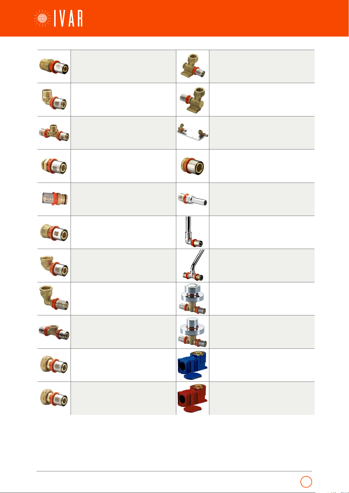
SPECIAL FIGURES
U-Fittings
As well as properly distributing water to all connected components, any sanitary DHW/DCW plumbing system must guar-
antee the best hygienic conditions possible by preserving the quality of the mains water supply.
A sanitary DHW/DCW distribution system is composed of different sections of piping:
Main distribution ring
Ascending or descending risers
Horizontal distribution sections to the floors
Connections to the terminal units (i.e. basins, baths, showers etc.)
There are several possible options for these. The two best known are shown in the following images, with branch connec-
tion (left) or via manifold (right), which are not ideal from a sanitary perspective.
Figure 2 Branch system. Figure 3 Manifold system.
Indeed, those pipe segments serving rarely used components suffer from a lack of water circulation, meaning the water
in these becomes stagnant. The same water sitting inside pipes over a long period of time encourages the proliferation of
bacteria (including legionella), and should therefore be avoided as much as possible.
IVAR’s MP range of fittings includes the 5780 series, which is essential for installations such as those shown in the follow-
ing figures and which implement a series- (left) and a ring- (right) type distribution system.
Figure 4 Series distribution system. Figure 5 Ring distribution system.
In both cases, the goal of these configurations is to facilitate water circulation in the pipes, thus avoiding stagnation and
reducing health risks. In the case of series distribution (left), the component used most frequently should be in the furthest
position from the column so that every time this is used, the water is replaced completely through circulation in all the
branches. In the case of ring distribution (right), the use of any plumbing fixture achieves the same result, making this dis-
tribution system the most effective for reducing hygienic risk. Depending on given regulations, there may be a requirement
to build facilities for hospitals and community structures using a ring distribution system, including an automatic withdrawal
point activated by timer. This ensures periodic water circulation in the system up to the terminal units during the thermal
disinfection cycles.
Under-floor distribution box fitting
Multilayer pipes are installed in corrugated conduit in some systems, for example,
when additional protection is required or in countries where installation regulations
require the pipes to be removable. For connection to the terminal units in these cases,
the MP5610 series under-floor distribution box fittings are required.
Made with a 1/2"
F connection, these accommodate the corrugated protective conduit inside, keeping
the pipe insulated up to the point of exit from the masonry wall. The CW617N brass
fitting is fixed to the plastic box by a pair of screws, so that it can be easily disassembled
for crimping and then reinserted in the box.
Figure 6 Hidden distribution.