IVEK MULTISPENSE 900 User manual

MULTISPENSE 900 W/TOUCHSCREEN CONTROLLER MODULE Page 3-1
27 March, 2015 IVEK Corp. P03R009O
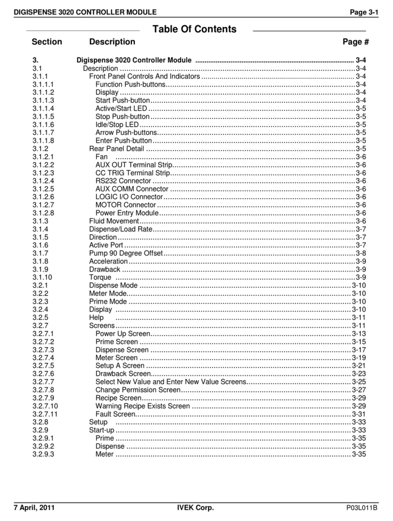
Table Of Contents
Section Description
Page #
3. Multispense 900 W/Touchscreen Controller Module
.......................................................
3-2
3.1 Description ......................................................................................................................... 3-2
3.1.1 Front Panel Controls & Indicators .................................................................................. 3-2
3.1.2 Rear Panel Detail ........................................................................................................... 3-3
3.2 Operation ........................................................................................................................... 3-6
3.2.1 Drive System .................................................................................................................. 3-6
3.2.2 Touchscreen ................................................................................................................... 3-6
3.2.3 PLC Interface ................................................................................................................ 3-24
3.2.4 Operating Modes .......................................................................................................... 3-26
3.2.5 Operating Parameters .................................................................................................. 3-27
3.2.6 Status Information ........................................................................................................ 3-28
3.3 Installation ........................................................................................................................ 3-28
3.4 Options .......................................................................................................................... 3-28
3.4.1 PLC Interface With Independent Channel Ready ........................................................ 3-28
3.4.2 PLC Interface With Independent Channel Trigger ....................................................... 3-29
3.4.3 Touchscreen ................................................................................................................. 3-29
3.5 Maintenance .................................................................................................................... 3-30
3.5.1 Assembly/Disassembly Procedures ............................................................................. 3-30
3.6 Problem Guide ................................................................................................................. 3-33
3.6.1 Serial Interface ............................................................................................................. 3-33
3.7 Specifications ................................................................................................................... 3-41
3.8 Model Number ................................................................................................................. 3-44
3.9 Illustrated Parts Breakdown ............................................................................................. 3-45

MULTISPENSE 900 W/TOUCHSCREEN CONTROLLER MODULE Page 3-2
27 March, 2015 IVEK Corp. P03R009O
3. MULTISPENSE 900 W/TOUCHSCREEN CONTROLLER MODULE
3.1 DESCRIPTION
The Multispense 900 W/Touchscreen Controller Module, hereafter referred to as the Controller Module, contains all
the control, monitoring, and interface components for the dispensing operations. The operator controls and interface
connections are located on the front and rear panels.
3.1.1 Front Panel Controls & Indicators (Figure 3.1)
The front panel of the Controller Module is made up of the Touchscreen, and individual front panels of the
Multispense Master Plug-In PCB (Printed Circuit Board), hereafter referred to as the Master Plug-In and Multispense
900 Channel Plug-In PCB(s), hereafter referred to as the Channel Plug-In(s).
3.1.1.1 Touchscreen (Figure 3.1 Item 1)
The touchscreen is the operator interface for controlling the system. Multiple screens are provided for setting and monitoring
system parameters. With a touch of the screen, parameters can be viewed and changed to meet specific requirements.
3.1.1.2 Master Plug-In Front Panel (Figure 3.1 Item 3)
Serial Interface data Indicators (2) - A red LED (Light Emitting Diode) indicates data being received by the Master
Card, a green LED indicates data being transmitted by the Master Plug-In.
3.1.1.3 Channel Plug-In Front Panel (Figure 3.1 Item 4)
Enabled Indicator (5) - (green) illuminates while this channel is enabled for operation.
Disabled Indicator (6) - (red) illuminates while this channel is NOT enabled for operation.
4
1
3
5
6
7
8
9
2
10
11
12
Refer to Figure 3.17 for
Touchscreen dimensions
Figure 3.1 Multispense 900 Controller Module Front Panel

MULTISPENSE 900 W/TOUCHSCREEN CONTROLLER MODULE Page 3-3
27 March, 2015 IVEK Corp. P03R009O
Enable Switch (7) - This switch allows this channel to be enabled or disabled. Move the switch on the top (SELECT
momentary) position and release to alternate between ENABLE and DISABLE. If the channel is disabled in this
manner, it will be enabled the next time the power is turned "on". The bottom (LOCKOUT maintained) position will
disable the channel, including when power is turned "on", as long as the switch remains at the LOCKOUT position.
Use LOCKOUT to insure a particular Motor/Base Module will not be operated. There is No warning on the
touchscreen that a channel is disabled.
When a serial interface is used in place of the touchscreen, the channel cannot be enabled using the serial interface
while this switch is in the LOCKOUT position.
Active Indicator (8) - (green) illuminates while pump is operating.
Idle Indicator (9) - (red) illuminates while pump is not operating.
Drawback Indicator (10) - (yellow) illuminates when the pump is in the drawback portion of a cycle.
Fault Indicator (11) - (red) illuminates when there is any system or pump fault.
Motor/Base Module Connector (12) - A Channel Plug-In for a standard Motor/Base Module will have a 14 pin female
connector.
3.1.2 Rear Panel Detail (Figure 3.2)
The rear panel of your Controller Module will look similar to either Figure 3.2A or Figure 3.2B. If your system is 4 or
fewer channels it will look similar to Figure 3.2A. If your system is 5 or more channels it will look similar to Figure 3.2B.
3.1.2.1 Fan (Figure 3.2A Item 1)
The fan cools the inside of the Controller Module when power is applied. Check the air filter on a regular basis to
ensure it is not restricting the air flow.
3.1.2.2 Motor Fuse Holder and Fuse (Figure 3.2A Item 2 and Figure 3.2B Item 8)
The Motor Fuse Holder houses the fuse for protecting the motor from an over current condition. To remove the fuse,
push in slightly and turn in a counter-clockwise direction. Refer to the Title Page section of the manual for the fuse
requirements.
3.1.2.3 Fan Fuse Holder and Fuse (Figure 3.2A Item 3 and Figure 3.2B Item 5)
The Fan Fuse Holder houses the fuse for protecting the fan from an over current condition. To remove the fuse, push
in slightly and turn in a counter-clockwise direction. Refer to the Title Page section of the manual for the fuse
requirements.
3.1.2.4 Touchscreen Fuse Holder and Fuse (Figure 3.2A Item 4 and Figure 3.2B Item 4)
The Touchscreen is an option on this controller, but is not covered in this manual. Refer to the Multispense 900 W/
Touchscreen Controller Module manual.
3.1.2.5 Logic Fuse Holder and Fuse (Figure 3.2A Item 5 and Figure 3.2B Item 3)
The Logic Fuse Holder houses the fuse for protecting the logic circuit from an over current condition. To remove the
fuse, push in slightly and turn in a counter-clockwise direction. Refer to the Title Page section of the manual for the
fuse requirements.

MULTISPENSE 900 W/TOUCHSCREEN CONTROLLER MODULE Page 3-4
27 March, 2015 IVEK Corp. P03R009O
3.1.2.6 Motion System Control Interface Type A Connector (Figure 3.2A Item 6 and Figure 3.2B Item 9)
The Motion System Control Interface Type A is an option on this controller. Refer to section 3.4.3 for additional
information.
3.1.2.7 Trigger In Terminal Block (Figure 3.2A Item 7 and Figure 3.2B Item 13)
The Trigger In terminal block is an option on this Controller Module. Refer to section 3.4.4 for additional information.
3.1.2.8 Touchscreen Connector (Figure 3.2A Item 8 and Figure 3.2B Item 10)
The Touchscreen is an option on this controller, but is not covered in this manual. Refer to the Multispense 900 W/
Touchscreen Controller Module manual.
3.1.2.9 Power Entry Module (Figure 3.2A Item 9)
The power entry module contains a receptacle for a standard IEC power cord, a voltage selector switch and main fuse
holder.
1
2
3
4
5
6
7
8
9
10
11
Figure 3.2A Multispense 900 1 - 4 Channel Controller Module Rear Panel
Figure 3.2B Multispense 900 5 - 32 Channel Controller Module Rear Panel
1
2
3
4
5
6
7
8
9
10
11
12
13
14

MULTISPENSE 900 W/TOUCHSCREEN CONTROLLER MODULE Page 3-5
27 March, 2015 IVEK Corp. P03R009O
CAUTION
Before plugging in the system, insure the line voltage setting appearing in the window agrees with the
available line voltage. Damage to the equipment could result if the two voltages do not match.
Refer to the Title Page section of this manual to determine the power connection and fuse specifications for this
Controller Module.
The design of the power entry module requires the line cord be disconnected before either the voltage select switch is
changed or a line fuse is removed. Perform the following steps if it is necessary to change the setting of the line
voltage select switch.
1. Disconnect the line cord at the power entry module and open its cover.
2. Remove the selection cam from the unit and replace it oriented so the desired voltage will appear in the
window when the cover is closed.
CAUTION
Rotating the voltage select cam while it is in the module may damage the module.
3. With the voltage select cam in the proper position, close the cover and replace the line cord. If the cover
does not completely close, open the cover and slightly reposition the voltage select cam.
3.1.2.10 System PLC Connector (Figure 3.2A Item 10 and Figure 3.2B Item 11)
The PLC connector (Amp Series One CPC 9 pin) is used for making the electrical connection to the PLC Interface
Device. Refer to section 3.2.2 for additional information.
3.1.2.11 Channel PLC Inputs and Outputs Connector (Figure 3.2A Item 11 and Figure 3.2B Items 12 and 14)
The Channel PLC Inputs and Outputs is an option on this Controller Module. Refer to Sections 3.4.1 and 3.4.2 for
additional information
3.1.2.12 Power Cord, Main Fuse Holder and Fuse (Figure 3.2B Items 1 and 2)
The power cord is provided with large multiple channel systems. A separate system fuse holder and fuse are located
near the power cord. The system is factory configure for the proper line voltage. To remove the fuse, push in slightly
and turn in a counter-clockwise direction. Refer to the Title Page section of this manual to determine the power
connection and fuse specifications for this Controller Module.
3.1.2.13 Motor Low Voltage Circuit Breaker (Figure 3.2B Item 6)
The Motor Low Voltage Circuit breaker protects the low voltage side of the motor from an over current condition. The
circuit breaker should be in the up (ON) position during normal operation. If the switch is not in the up (ON) position
there may be a problem with the system. Push the switch up, if it switches to the down (OFF) position call IVEK
Technical Support.
3.1.2.14 Motor High Voltage Circuit Breaker (Figure 3.2B Item 7)
The Motor High Voltage Circuit breaker protects the high voltage side of the motor from an over current condition. The
circuit breaker should be in the up (ON) position during normal operation. If the switch is not in the up (ON) position
there may be a problem with the system. Push the switch up, if it switches to the down (OFF) position call IVEK
Technical Support.

MULTISPENSE 900 W/TOUCHSCREEN CONTROLLER MODULE Page 3-6
27 March, 2015 IVEK Corp. P03R009O
3.2 OPERATION
The Controller Module provides the controls for producing liquid flow via a positive displacement pumping mechanism.
The systems utilize solid-state electronics, stepping motor drives, and precision machined ceramic pump heads.
These components combine to provide exceptional accuracy and precision, high reliability, and low maintenance.
IVEK units have custom designed stepping motors and pumps sized to the specific dispensing application to provide
the proper torque and speed.
Volume commands for the Controller Module use number of full revolutions. Rate commands are in revolutions per
minute. The typical resolution of the pumps used is 200 steps per revolution, or 1.8° per step.
3.2.1 Drive System
All operational parameters on the Controller Module are programmed through the touchscreen. Total electronic
control allows for full accountability of cumulative volumes dispensed.
3.2.2 Touchscreen
The touchscreen provides an operator interface to all operating parameters in the Controller Module. New values can
be entered and current values displayed for all the functions of the system. The touchscreen contains nine different
operator interface screens with each providing information to the operator. Start and Stop buttons appear on two
screens for starting and stopping the system.
3.2.2.1 Introduction
Configurations - A configuration is a collection of the operating parameters required to operate the system. The
operating parameters include volume, rate, direction and drawback. For each configuration, the parameters are stored
in the configuration database. All channels use the same value for a given parameter.
Buttons - A button initiates a command being sent to the IVEK Multispense 900 Controller Module. The "Start" and
"Stop" area in the Main screen (Figure 3.8) are examples of buttons.
Boxes - A box looks identical to a button, but provides information only. Pressing a box will have no effect on the
system. The "CHANNEL" and "DESCRIPTION" area in the Fault Screen (Figure 3.13) are examples of boxes.
Screens - There are nine screens used to setup, operate and exit the system as shown in Figure 3.3. Each screen
contains information relating to operating the system. The screens and a brief description are as follows:
Main Screen Volume, Rate and Drawback settings are viewed here. The system can be operated from this screen.
Volume & Rate Screen Volume and Rate settings are viewed and changed here. The system can be operated from this
screen.
Configuration Screen Configurations are changed and stored with this screen. Any parameters changed outside the
configuration will not be saved as a configuration.
Params A Screen Displays Totalizer, Permission, Prime Duration and Ready Out information.
Params B Screen Displays software versions and Controller serial number. Acceleration setting is viewed and
changed (Microspense only).
Drawback Screen Drawback and Stall Retries settings are viewed and changed here.
Fault Screen Faults are displayed and cleared.
Clear Totalizer Screen Clears all totalizer values.
Exit Screen Exit the software.
Figure 3.3 shows the screens and provides an overview of the function of each screen. Lines and arrows show
accessibility for each screen.

MULTISPENSE 900 W/TOUCHSCREEN CONTROLLER MODULE Page 3-7
27 March, 2015 IVEK Corp. P03R009O
MAIN SCREEN
• Start
• Stop
• Ready Indicator
• View Parameters
FAULT SCREEN
VOLUME & RATE SCREEN
• View Faults
• Start
• Volume
CONFIG SCREEN
• Clear Faults
• Stop
• Disp/Meter Rate
• View/Edit Configurations
• Reference Channels
• Direction
• Priming Rate
• Mode
• Ready Indicator
• Connection Status
DRAWBACK SCREEN
• Volume • Dwell
• Rate • Stall Retries
PARAMS A SCREEN
CLEARTOTALIZER
• Totalizer Functions
SCREEN
• Change Permission
• Clear Totalizers
• Prime Duration
• Ready Out Config
PARAMS B SCREEN
•Software Version
•Change Permission
•Serial Number
•Acceleration
(Microspense Only)
EXIT SCREEN
• Exit Software
Figure 3.3 Screen Information

MULTISPENSE 900 W/TOUCHSCREEN CONTROLLER MODULE Page 3-8
27 March, 2015 IVEK Corp. P03R009O
Another display, called the Keypad, only appears on the top of screens. The Keypad is used for changing the selected
parameter and is shown in Figure 3.4.
Displays the value being entered.
Displays minimum and maximum settings.
Numerical Keypad.
"Enter" loads the value into the selected
parameter. "BS" deletes the last digit entered.
Moves the keypad left and right on the screen.
Deletes any entered value in the display and removes the keypad screen.
Figure 3.4 Keypad Display
3.2.2.2 Permission Levels
There are three levels of permission; Operator, Manual and Supervisor. Each level allows access to selected items on
the touchscreen.
The permission level can be changed by using the "Change Permission" button in the Params A or Params B screen.
Click on the button to display the Keypad then type in the password for the required permission and press the
"ENTER" key.
The highest level is Supervisor. This level allows access to all items on all screens.
The Manual level allows access to all items on all screens except changing values in the Configurations and access
to the "EXIT" button on the Params A screen.
The Operator level does not allow changing system parameters. Configurations can be selected and loaded, but not
changed.
If a button is not available because of the permission level, a security flag will be present over the button. Figure 3.5
shows the permission flag.
Figure 3.5 Permission Flag
3.2.2.3 Getting Started
The touchscreen will "Boot" when the power to the Controller Module is turned on. If the program is accidently exited,
the Controller Module must be turned off and then back on. The "Boot" sequence will be visible on the Touchscreen
and takes approximately one minute.
The last values entered into the touchscreen before it was turned off will appear after the system has booted.

MULTISPENSE 900 W/TOUCHSCREEN CONTROLLER MODULE Page 3-9
27 March, 2015 IVEK Corp. P03R009O
The first screen displayed will be the Main screen containing the last parameter settings. Usually, the last parameter
setting is either Dispense or Meter mode so it is a good idea to first go to the Configuration screen or enter the setting
manually in the Volume & Rate and Drawback screens.
If the touchscreen cannot communicate with the Multispense 900 Controller Module, a fault will occur. The fault can
be cleared in the Fault screen. (Section 3.2.2.10) The communications flag shown in Figure 3.6 may also be displayed
on the Touchscreen.
Figure 3.6 Communications Flag
3.2.2.4 Configuration Screen (Figure 3.7)
The Configuration screen displays the parameter settings for each of the twenty five configurations. The system
arrives with a few configurations preset and the remaining configurations set with default parameters. The current
permission level determines which buttons are currently available as shown in Figure 3.7.
The configurations are the recommended method of changing operating parameters. Once a configuration has been
created or changed it is available to use each time the system is used. Parameters not saved in configurations will be
lost once the system is turned off.
The twenty five configurations are named Configuration 1 through Configuration 25. The current configuration number is
displayed in the Main screen. Each configuration can be programmed to perform a specific job function. All configuration
parameters are numerical values and must be entered in the keypad as numbers. To use a preset configuration:
1. Use the "CONFIG ->" and "<- CONFIG" buttons to move to the desired configuration.
2. Press the "USE CONFIG" button to load the parameters into the Controller Module.
To change a configuration;
1. Use the "CONFIG ->" and "<- CONFIG" buttons to move to the desired configuration.
2. Use the "PREV ITEM" and "NEXT ITEM" buttons to select the parameter.
3. Press the "EDIT ITEM" button.
4. The keypad appears with the minimum and maximum settings displayed.
5. Type the new parameter number.
NOTE
If a number smaller than the minimum is entered, a message will appear stating the minimum number which
can be entered.
If a number larger than the maximum is entered, a message will appear stating the maximum number which
can be entered.
6. When all parameters are entered, press "SAVE CHANGES" or "IGNORE CHANGES".
7. To start using the new configuration press the "USE CONFIG" button. This will load the parameters into the
Controller Module.
An * appears in front of edited items until the changes are saved or ignored.

MULTISPENSE 900 W/TOUCHSCREEN CONTROLLER MODULE Page 3-10
27 March, 2015 IVEK Corp. P03R009O
The Configuration
screens allow generat-
ing, changing and
using preset param-
eters
(See below for a descrip-
tion of each section)
Moves the cursor to the parameter above. √√√
Moves the cursor to the parameter below. √√√
Displays the keypad screen for making changes to the √
highlighted parameter.
Switches to the Main screen. √√√
Lists the parameter settings for each configuration. (1 - 25)
A * in left column indicates edited parameter.
Switches to the next configuration. √√√
Switches to the previous configuration. √√√
Loads the selected configuration for use. √√√
Saves any changes made to the current configuration. √
Cancels any changes made to the current configuration. √
Figure 3.7 Configuration Screen
Operator
Manual
Supervisor

MULTISPENSE 900 W/TOUCHSCREEN CONTROLLER MODULE Page 3-11
27 March, 2015 IVEK Corp. P03R009O
3.2.2.5 Main Screen (Figure 3.8)
The Main screen displays the parameter settings currently in use. The Main screen is normally used to operate the
system. The Fault, Configuration and Vol & Rate screens are accessible from this screen. All the buttons on this
screen are accessible by all permission levels.
NOTE
If a configuration has been selected and the parameters changed in the Volume & Rate or Drawback screens
the Main screen will display the changed parameters.
The "START" button will start the system using the current parameters. The system will operate until the cycle is
completed or the "STOP" button is pressed. The "Ready" box indicates the state of the READY output in the PLC
Interface. If the system is not Ready, the icon will change color and display "Busy".
The current configuration and Permission access level are displayed. The Configuration number will normally be a
number from 1 to 25 indicating the current configuration. "MODIFIED" will be displayed when the access level was
Manual or Supervisor and was then changed to Operator without a configuration being selected. This indicates the
parameters displayed may not be the same as one of the 25 configurations.
3.2.2.6 Volume & Rate Screen (Figure 3.9)
The Volume & Rate screen displays the primary operating parameters for the configuration selected in the
Configuration screen. This screen is used to change parameters for custom dispenses. The current permission level
determines which buttons are currently available as shown in Figure 3.9.
NOTE
Parameters changed in this screen will not be saved if a different configuration is selected.
The system can be operated from this screen. The Fault, Drawback and Main screens are accessible from this screen.
Volume Strokes
Volume Strokes is number of revolutions the motor turns for one dispense operation. To change the Volume Strokes value;
1. Press the "SET" button.
2. The keypad appears with the minimum and maximum settings displayed.
3. Enter the value using the number keypad.
4. Press the "ENTER" button.
Disp/Meter Rate
The Disp/Meter rate is the speed of the motor in revolutions per minute during the dispense and meter operations. To
change the Disp/Meter Rate value;
1. Press the "SET" button.
2. The keypad appears with the minimum and maximum settings displayed.
3. Enter the value using the number keypad.
4. Press the "ENTER" button.

MULTISPENSE 900 W/TOUCHSCREEN CONTROLLER MODULE Page 3-12
27 March, 2015 IVEK Corp. P03R009O
The Main screen
controls the system
and displays the
operating parameters
(See below for a descrip-
tion of each section)
Displays the current Volume setting in strokes.
Displays the current Dispense/Meter Rate setting in RPM.
Displays the current Priming Rate setting in RPM.
Displays the current mode (Prime / Dispense / Meter)
Displays the current direction (Forward / Reverse)
Displays the current Drawback Volume setting in strokes.
Displays the current Drawback Rate setting in RPM.
Displays the current Drawback Dwell setting in seconds.
Displays the current configuration (1 - 25 or MODIFIED).
Displays the current permission level.
Starts the current mode of operation.
Stops the current mode of operation.
Indicates the state of the READY output in the PLC Interface.
Switches to the Fault screen. Button changes
to when a channel is faulted.
Switches to the Configuration screen.
Switches to the Volume & Rate screen.
Figure 3.8 Main Screen

MULTISPENSE 900 W/TOUCHSCREEN CONTROLLER MODULE Page 3-13
27 March, 2015 IVEK Corp. P03R009O
Priming Rate
The Priming rate is the speed of the motor in revolutions per minute during the priming operations. To change the
Priming Rate value;
1. Press the "SET" button.
2. The keypad appears with the minimum and maximum settings displayed.
3. Enter the value using the number keypad.
4. Press the "ENTER" button.
Operating Mode
The "PRIME / DISPENSE / METER" button indicates the current mode of operation. The button will display only the
current mode.
Prime mode produces a continuous cycle to pump fluid in one direction. Prime is used to fill the system with fluid in
preparation for actual operation, empty the system of fluid, and flush the system for cleaning.
Dispense mode is used to deliver a specific volume of fluid at a specific rate. The current settings for the fluid
direction determine the direction of fluid flow.
Meter mode is used to deliver fluid at a specific rate for the period of time the system is active.
To change the Operating Mode;
1. Press the button displaying the current mode.
2. The button will cycle through PRIME / DISPENSE / METER.
3. Stop at the desired mode.
Liquid Direction
The "FORWARD / REVERSE" button indicates the current liquid direction. The button only displays the current
direction. To change the Liquid Direction;
1. Press the button displaying the current direction.
2. The direction button will change to display the new direction.

MULTISPENSE 900 W/TOUCHSCREEN CONTROLLER MODULE Page 3-14
27 March, 2015 IVEK Corp. P03R009O
The Volume and Rate
screen is used to set
volume and rate
parameters
(See below for a descrip-
tion of each section)
Displays the current Volume Strokes setting.
Pressing enables the entry keypad for changing
the setting.
Displays the current Dispense and Meter Rate
setting in rev/min. Pressing enables the entry
keypad for changing the setting.
Displays the current Priming Rate setting in rev/min.
Pressing enables the entry keypad for changing
the setting.
Displays the current operating mode. When pressed
toggles between Prime, Dispense and Meter.
Starts the current mode of operation.
Stops the current mode of operation.
Indicates the state of the READY output in the PLC
Interface.
Indicates a current fault condition and when pressed
switches to the Fault Screen.
Switches to the Drawback screen.
Switches to the Main screen.
Displays the current direction. When pressed
toggles between Forward and Reverse
Figure 3.9 Volume And Rate Screen
Operator
Manual
Supervisor
√√√
√√
√√√
√
√√√
√√√
√√√
√√
√√
√√
√√
√√√
√√√

MULTISPENSE 900 W/TOUCHSCREEN CONTROLLER MODULE Page 3-15
27 March, 2015 IVEK Corp. P03R009O
3.2.2.7 Drawback Screen (Figure 3.10)
The Drawback screen displays parameters which control Drawback operation settings for the configuration selected in the
Configuration screen. This screen is used to change drawback parameters for custom dispenses. Drawback is a controlled
reverse flow at the end of a dispense to improve volume repeatability when 'stringy' liquids are being dispensed. At the end
of the dispense cycle, the motor will reverse pulling the liquid back into the liquid line. The Controller Module will
automatically compensate for the drawback volume, the dispense volume value must not be adjusted.
The current permission level determines which buttons are currently available as shown in Figure 3.10.
NOTE
Parameters changed in this screen will not be saved if a different configuration is selected.
The Params A and Vol & Rate screens are accessible from this screen.
Drawback Volume Strokes
Volume Strokes is a fractional number, to a resolution of one hundredth of a stroke, of reverse revolutions the motor
turns for one drawback operation. To change the Volume Strokes value;
1. Press the "SET" button.
2. The keypad appears with the minimum and maximum settings displayed.
3. Enter the value using the number keypad.
4. Press the "ENTER" button.
Drawback Rate
The Drawback rate is the number of revolutions per minute the motor turns during the drawback operations. To
change the Rate value;
1. Press the "SET" button.
2. The keypad appears with the minimum and maximum settings displayed.
3. Enter the value using the number keypad.
4. Press the "ENTER" button.
Drawback Dwell
The Drawback Dwell is the amount of time between the end of the Dispense or Meter operation and the start of the
Drawback operation.
To change the Dwell value;
1. Press the "SET" button.
2. The keypad appears with the minimum and maximum settings displayed.
3. Enter the value using the number keypad.
4. Press the "ENTER" button.

MULTISPENSE 900 W/TOUCHSCREEN CONTROLLER MODULE Page 3-16
27 March, 2015 IVEK Corp. P03R009O
The Drawback screen
is used to set drawback
and configuration
parameters
(See below for a descrip-
tion of each section)
Displays the current Drawback Volume Strokes setting. Press-
ing enables the entry keypad for changing the setting.
Displays the current Drawback Rate setting in rev/min. Pressing
enables the entry keypad for changing the setting.
Displays the current Drawback Dwell setting in sec. Pressing
enables the entry keypad for changing the setting.
Displays the current Stall Retries setting. Pressing enables
the entry keypad for changing the setting.
Switches to the Params A screen.
Switches to the Volume and Rate screen.
Figure 3.10 Drawback Screen
Operator
Manual
Supervisor
√√
√√
√√
√√
√√√
√√√

MULTISPENSE 900 W/TOUCHSCREEN CONTROLLER MODULE Page 3-17
27 March, 2015 IVEK Corp. P03R009O
Stall Retries
Stall Retries is the number of times the motor will try turning before a fault is generated and is generally set at 4. A
stall is detected when the Controller Module has commanded the motor to turn one revolution without receiving a
signal from a sensor on the Motor/Base Module. If 'Stall Retries' is"1", the channel will fault. Otherwise, after a short
idle delay, the Controller Module will again command the motor to turn. Select the number of "Stall Retries" for the
Controller Module to attempt before a Fault is generated. To change the Stall Retries;
1. Press the "SET" button.
2. The keypad appears with the minimum and maximum settings displayed.
3. Enter the value using the number keypad.
4. Press the "ENTER" button.
3.2.2.8 Params A Screen (Figure 3.11)
The Params A screen displays certain system parameters and Permission information. This screen is used to clear
the totalizer and change the permission level. The current permission level determines which buttons are currently
available as shown in Figure 3.11.
The Clear Totalizer, Params B, Main and Exit screens are accessible from this screen.
Totalizer
The "TOTALIZER" box displays the volume dispensed in motor rotations for the channel indicated below. This will
normally be the same number for all enabled channels.
To clear the Totalizer for the selected channel;
1. Press the "CLEAR SELECTED TOTALIZER" button.
To clear the Totalizer for all channels;
1. Press the "CLEAR ALL TOTALIZERS" button.
2. The Clear Totalizer screen is displayed.
3. Press the "CLEAR TOTALIZERS FOR ALL CHANNELS" button to clear the totalizer or press the "PARAMS
A SCREEN" button to cancel.
Change Permission
The "Change Permission" button displays the keypad for changing the permission level to the software. There are
three levels; Supervisor, Manual, and Operator (Refer to section 3.2.2.2). To change the Permission level;
1. Press the "CHANGE PERMISSION" button.
2. The keypad will appear.
3. Enter the password code for the desired permission level.
4. Confirm the display shows the desired level.
Prime Duration
The Prime Duration is the maximum amount of seconds the system will operate during one Prime operation. This
should be adjusted for operational requirements to reduce "floods". To change the Prime Duration;
1. Press the "SET" button.
2. The keypad appears with the minimum and maximum settings displayed.
3. Enter the value using the number keypad.
4. Press the "ENTER" button.

MULTISPENSE 900 W/TOUCHSCREEN CONTROLLER MODULE Page 3-18
27 March, 2015 IVEK Corp. P03R009O
The Params A screen
displays system
param-eters and user
informa-tion
(See below for a descrip-
tion of each section)
Displays the total volume dispensed for the selected channel.
Displays the selected channel for viewing the Totalizer value.
Pressing enables the entry keypad to change channels.
Pressing <- or -> changes the channel number by 1.
Switches to the Clear Totalizer screen.
When pressed, clears the selected channels totalizer value.
Displays the permission level.
Changes the permission level.
Displays the current Prime Duration setting in sec. Pressing
enables the entry keypad to change the setting.
Displays the current Ready Out Configuration setting.
Pressing enables the entry keypad to change the setting.
Switches to the Params B screen.
Switches to the Main screen.
Figure 3.11 Params A Screen
Operator
Manual
Supervisor
√√
√√
√√√
√√√
√√√
√√√
√√√
√√√

MULTISPENSE 900 W/TOUCHSCREEN CONTROLLER MODULE Page 3-19
27 March, 2015 IVEK Corp. P03R009O
Ready Out Config
The ready Out Configuration determines when the Ready Out signal will be false. The signal is always false during
dispense and meter operations.
Both the "SYSTEM READY" and optional "Independent Channel Ready" signals are configured with this value.
The following optional settings are available:
System
2
Priming (System Ready also false)
System
8
Any fault true, reference required (System Ready also false)
Channel
32
Priming (Channel Ready also false)
Channel
128
Any fault true, reference required (Channel Ready also false)
Default
138
System not ready if in Prime, fault or reference required. Channel not ready if fault or reference required.
Add the desired values listed above to determine the correct value for the "Ready Out Config" parameter. To change
the Ready Out Config;
1. Press the "SET" button.
2. The keypad appears with the minimum and maximum settings displayed.
3. Enter the value using the number keypad.
4. Press the "ENTER" button.
3.2.2.9 Params B Screen (Figure 3.12)
The Params B screen displays additional parameters not displayed in the Params A screen. This screen is used to
change the permission access and exit the software. The current permission level determines which buttons are
currently available as shown in Figure 3.12.
If the system uses Microspense motor/bases, view and change the current Acceleration value here. If the systemuses
standard or Heavy-Duty motor/bases, this area of the screen is blank. Most applications will use Standard
acceleration. Applications using single -stroke dispense and have a small volume being ejected from the dispense tip
may benefit from Fire-Off acceleration. High-viscosity fluids will not benefit from Fire-Off acceleration, and may stall as
a result of the reduced torque.
Information is displayed which may be requested by IVEK's Technical Service Department when locating the source
of problems. The software version of the Master Plug-In and Channel 1 Plug-In(s) and Touchscreen are displayed.
The serial number of the Controller Module is stored in the Touchscreen (entered during manufacture at IVEK
Corporation.
Insure the motor/base type (Microspense versus Standard and Heavy Duty) displayed on the touchscreen matches
the Controller Module Channel Plug-Ins and Motor/Base Modules being used. This insures the maximum and
minimum limits on values in the touchscreen matches those in the Controller Module.
The Main screen is accessible from this screen.
NOTE
There is no need to exit the Touchscreen program before powering down the Controller Module. IVEK
Technical Service may have you exit the program for calibration or troubleshooting.
The "EXIT" button is the only way to exit the software. To exit the software;
1. Press the "EXIT" button.
2. The Exit screen will appear.
3. Press "EXIT" to exit the software or "DON'T EXIT GO TO MAIN SCREEN" to cancel.

MULTISPENSE 900 W/TOUCHSCREEN CONTROLLER MODULE Page 3-20
27 March, 2015 IVEK Corp. P03R009O
The Params B screen
displays additional
system parameters
and user information
(See below for a descrip-
tion of each section)
Displays the software version for the Master
Plug-In and Channel 1 Plug-In.
Displays the current acceleration. When
pressed, toggles between Microspense
Acceleration: Standard and Microspense
Acceleration: Fire-Off. Not present for Standard
and Heavy-Duty motor/bases.
Displays the current Permission access level.
Changes the Permission access level.
Displays the Controller Module serial number.
Displays the software version and copyright.
Switches to the Exit screen.
Switches to the Main screen.
Figure 3.12 Params B Screen
√√√
√
√√√
Operator
Manual
Supervisor
Table of contents
Other IVEK Controllers manuals