brancher les conducteurs, faisant attention à la légende N L1 L2 L3 T et
successivement les fixer par le dispositif serre-câble.
Montage:
Insérer le connecteur dans le rail faisant attention à l’orientation correcte (Dx ou
Sx); après le fixer par la vis A comme dans la fig. 2.
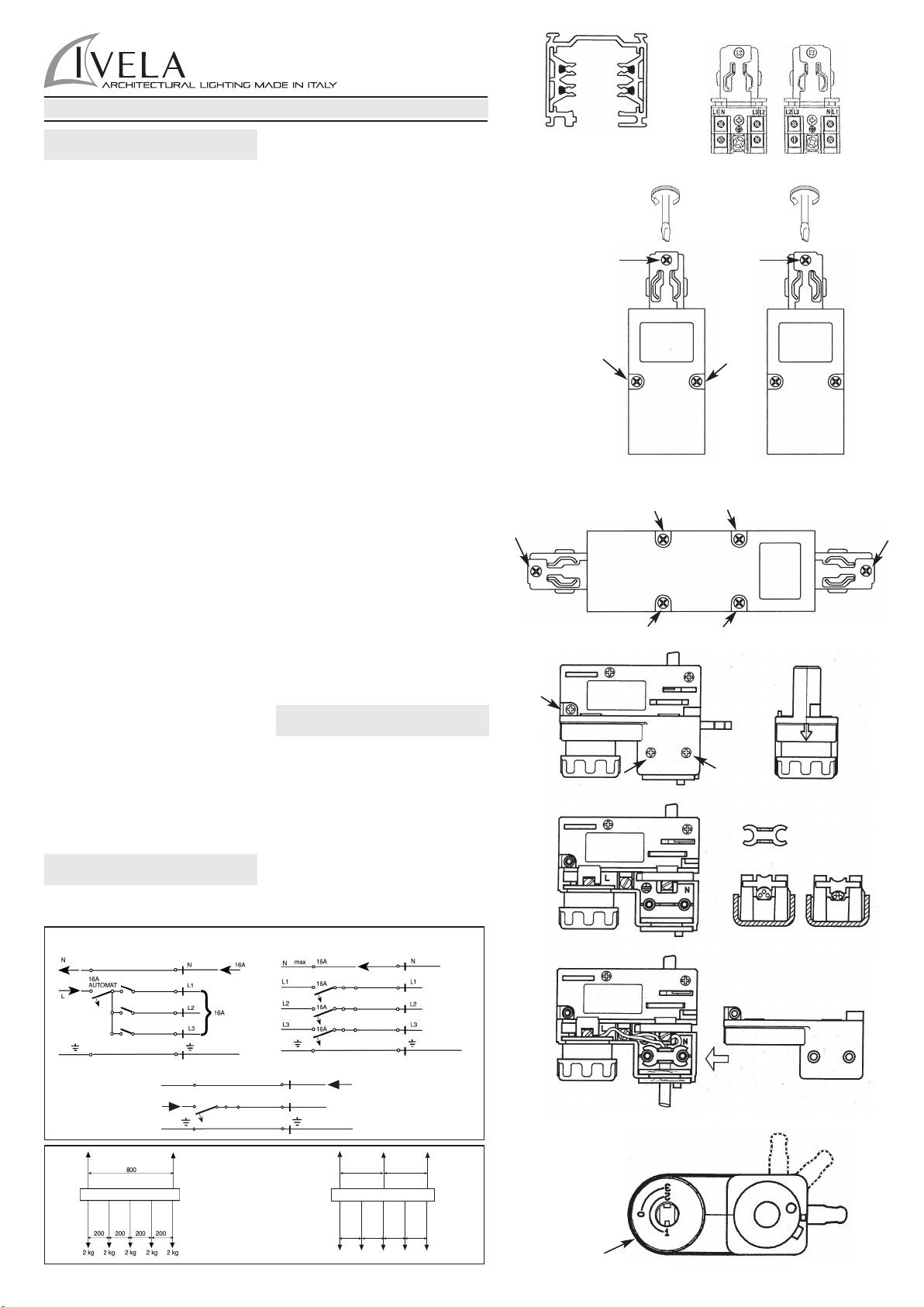
Alimentation médiane art. 7653 440 V 16A
Branchement:
Ouvrir le bôitier des contacts, dévissant les quatre vis comme dans la fig. 3.
Percer la pre-ouverture prévue pour le passage du câble, brancher les
conducteurs, faisant attention à la légende N L1 L2 L3 T et successivement les
fixer par le dispositif serre-câble.
Montage:
Insérer le connecteur dans le rail, faisant attention à l’orientation correcte (Dx ou
Sx) et après le fixer par les vis A comme dans la fig. 3.
Adaptateur pour rail art. 7601 250V 6A
Branchement:
Dévisser les trois vis comme dans la fig. 4A. Insérer le câble de l’appareil dans le
trou de la douille de rotation et le fixer par le dispositif correspondant, comme dans
la fig. 4D. Brancher les trois conducteurs faisant attention à la légende L N T
comme dans la fig. 4B et 4C.Remonter et fixer le couvercle. L’emploi est limité au
systéme rail spécìfié
Montage:
Insérer l’adaptateur dans le rail avec le levier D orienté comme dans la fig. 6,
position F, et après le fixer par la rotation de la position F à la position G. Après
sélectionner la phase désirée par la poignée E, comme dans la fig. 6. N’installez
pas d’appareils de poids supérieur à 50 N.
Montage à mur
En case de montage à mur avec le rail en position horizontale, n’appliquez pas à
l’adaptateur un moment de flexion supèrieur à 1 Nm. En cas de montage à mur
avec le rail en position verticale, la rainure de guide du profilé du rail doit être à
droite; n’appliquez pas à l’adaptateur un moment de flexion supérieur à 2 Nm.
Attention! Pour l’installation de spots de poids supérieur à 50 N, ou dépassant les
moments de flexion respectivement de 1 Nm et 2 Nm, employer l’adaptateur
mécanique art. 7625.
Installer/utiliser le produit autre que celle prescrit implique la perte de
caractéristiques techniques/mécaniques, par conséquent, annuler la garantie.
D - DREIPHASENSTROMSCHIENE ART. 7511
440V 16A CL1
Die Stromschiene und ihre Komponenten, inbegriffen die Adapter in Kl I, sind nicht
auswechselbar mit Stromschienesysteme in KI. III oder mit Zubehören, die kein
Qualitätzeichen zeigen. Der Benutzer ist dafür verantwortlich, die elektrische,
mechanische und thermische Kompatibilität zwischen den Stromschienesystemen
und den verbundenen Strahlern zu sichern. Eingriffe in die Elektroanlage ist nur
rechtlich qualifiziertem Fachpersonal erlaubt.
Montage
Installieren Sie die Stromschiene durch die auf dem Profil vorgebohrten Löcher,
oder benutzen Sie die Zubehöre Art. 7606 - Stahlseil-Abhänger oder Art. 7606 -
Kit für Decke, indem Sie die Ladengrenzen wie aus Bild 5 beachten.
Einspeisungsstücke art. 7652 Sx 440V 16A
Verbindung:
Öffnen Sie das Kontaktsgehäuse, indem Sie die zwei Schrauben wie im Bild 2
abschrauben. Schlagen Sie den Boden der vorbereiteten Öffnung aus, um das
Kabel durchzuziehen; verbinden Sie die Leitungen, indem Sie auf die Aufschrift N
L1 L2 L3 T achtgeben. Dann befestigen Sie sie durch die Klemme.
Montage:
Stecken Sie das Einspeisungsstück in die Stromschiene, indem Sie auf die
richtige Orientierung (Dx oder Sx) achtgeben, und dann befestigen Sie es mit der
Schraube A wie aus Bild 2.
Mittleres Einspeisungsstück Art. 7653 440V 16A
Verbindung:
Öffnen Sie das Kontaktsgehäuse, indem sie die vier Schrauben wie aus Bild 3
abschrauben. Schlagen Sie den Boden der vorbereiteten Öffnung aus, um das
Kabel durchzuziehen; verbinden Sie die Leitungen, indem Sie auf die Aufschrift N
L1 L2 L3 T achtgeben, und dann befestigen Sie sie mit der Klemme.
Montage:
Stecken Sie das Einspeisungsstück in die Stromschiene, indem Sie auf die
richtige Orientierung (Dx oder Sx) achtgeben, und dann befestigen Sie es mit den
Schrauben A wie aus Bild 3.
Steckadapter Art. 7601 250V 6A
Verbindung:
Schrauben Sie die drei Schrauben wie aus Bild 4A ab. Stecken Sie das Kabel des
Strahlers ins Loch der Büchse und befestigen Sie es mit der besonderen
Vorrichtung wie aus Bild 4D. Verbinden Sie die drei Leitungen, indem Sie auf die
Aufschrift L N T wie aus Bild 4B und 4C achtgeben. Legen Sie die Decke wieder
auf und befestigen Sie sie. Die Benutzung wird zurn angegebenen
Schienensystem eingeschränkt
Montage:
Stecken Sie den Adapter in die Stromschiene mit dem Hebel D wie aus Bild 6,
Lage F, gerichtet, dann befestigen Sie ihn, indem Sie den Hebel von der Lage F
zur Lage G drehen. Dann wählen Sie die gewünschte Phase durch den Griff E wie
aus Bild 6 aus. Installieren Sie keine Strahler mit einem Gewicht größer als 50 N.
Montage an der Wand
Wenn Sie die Stromschiene horizontal an die Wand installieren, legen Sie dem
Adapter ein Moment von Biegung nicht größer als 1 Nm an. Wenn Sie die
Stromschiene senkrecht an die Wand installieren, muß die Führungsnut des
Profils der Stromschiene rechts sein: legen Sie dem Adapter ein Moment von
Biegung nicht größer als 2 Nm an.
Achtung! Benutzen sie den mechanischen Adapter Art. 7625, um Strahler mit
einem Gewicht größer als 50 N zu installieren, oder wenn sie die Momente von
Biegung beziehungsweise von 1 Nm und 2 Nm übersteigen.
Installieren/Benutzen Sie das Produkt anders als verschrieben Beinhaltet den
Verlust von technischen/mechanischen Eigenschaften, damit die Garantie erlischt.
E - VÍA TRIFÁSICA Art. 7511
440V 16A CL1
La vía y sus componentes, incluidos los adaptadores de clase 1 no son
intercambiables con sistemas de vía de clase III o con accesorios que no posean
la Marca de Calidad.El usuario tiene la responsabilidad de garantizar la
compatibilidad eléctrica, mecánica y térmica entre los sistemas de vía y los
aparatos conectados a ella. Está permitido intervenir sobre la instalación eléctrica
solamente a personal competente legalmente reconocido.
Montaje
Instale la vía mediante los agujeros que ya están predispuestos en el perfil o bien
utilizando los accesorios Art. 7606 - Kit de suspensión o bien Art. 7607 - Kit techo,
con los límites de carga indicados en la fig. 5. Conectores de alimentación Art.
7652 Der. Art. 7652 Izq. 440V 16A
Conexión:
Abra el espacio portacontactos, destornillando los dos tornillos tal como se indica
en la fig. 2.
Penetre la pre-rotura para el paso del cable, conecte los conductores prestando
atención a la inscripción N L1 L2 L3 T y luego bloquéelo mediante la grampa
sujeta-cable.
Montaje:
Introduzca el conector en la vía prestando atención a que esté orientado
correctamente (Der. o Izq.) y luego bloquéelo con el tornillo A como en la fig. 2.
Alimentación central Art. 7653 440V 16A
Conexión:
Abra el espacio portacontactos destornillando los cuatro tornillos tal como se
indica en la fig. 3. Penetre la pre-rotura para el paso del cable, conecte los
conductores prestando atención a la inscripción N L1 L2 L3 T y luego bloquéelo
mediante la grampa sujeta-cable.
Montaje:
Introduzca el conector en la vía prestando atención a que esté orientado
correctamente (Der. o Izq.) y luego bloquéelo con los tornillos A como se indica en
la fig. 3.
Adaptador para vía Art. 7601 250V 6A
Conexión:
Destornille los tres tornillos como se indica en la fig. 4A. Introduzca el cable del
aparato a través del agujero del casquillo de rotación y fíjelo mediante la
correspondiente grampa como se indica en la fig. 4D. Conecte los tres
conductores prestando atención a la inscripción L N T como se indica en las
figuras fig. 4B y 4C. Monte nuevamente y fije la tapa. El uso queda limitado al
sistema vía especificado
Montaje:
Introduzca el adaptador en la vía con la palanca D orientada como se indica en la
fig. 6 posición F y luego bloquéela girándola de la posición F a la posición G.
Luego seleccione la fase deseada mediante el botón E como se indica en la fig. 6.
No aplique aparatos de un peso que supere los 50N.
Montaje de pared:
En el caso del montaje de pared con la vía en posición horizontal, no aplique al
adaptador un momento flector superior a 1Nm. En el caso de montaje de pared
con la vía en posición vertical, la ranura de guía del perfil de la vía debe estar a la
derecha; no aplique al adaptador un momento flector superior a 2Nm.
¡Atención! Para la instalación de focos que posean un peso superior a los 50N o
que superen los momentos flectores, respectivamente, de 1Nm y 2Nm, utilice el
adaptador mecánico Art. 7625.
Instalar/usar el producto que no sea como se prescrito implica la pérdida de las
características técnicas/mecánicas, por tanto invalidar la garantía.
NL - DRIEFASE RAILS art. 7511
440V 16A CL1
De rails en zijn uitrusting, inbegrepen de adapters van klasse I, zijn niet te
vervangen met railssystemen van klasse III of accessoires die niet van het
Kwaliteitsmerk voorzien zijn. De gebruiker is verantwoordelijk voor de elektrische,
mechanische en thermische compatibiliteit tussen de railssystemen en de
daaraan gesloten apparatuur. Het is alleen aan wettelijk erkend, gekwalificeerd
personeel toegestaan aan de electrische installatie te werken.
Montage
De rails via de al aangebrachte gaten op het profiel monteren of een van de
volgende accessoires gebruiken art. 7606 – Ophangkit, of art. 7607 – Plafondkit,
volgens de in fig. 5 aangegeven maximale belastbaarheid. Voedingsconnectoren
art. 7652 Dx art. 7652 Sx 440V 16A
Aansluiting:
De contacthouder ruimte openen door de twee schroeven los te draaien, zoals
aangegeven in fig. 2. De breekdeksel voor de kabeldoorvoer verwijderen, de
geleiders aansluiten, door goed op de opschrift N L1 L2 L3 T te letten, en ze met
de kabelstrip blokkeren.
Montage:
De connector in de juiste richting (Rechts of Links) in de rails steken en met de
schroef A blokkeren, zoals in fig. 2 aangegeven. Voeding vanuit het midden art.
7653 440V 16A
Aansluiting:
De contacthouder ruimte openen door de vier schroeven los te draaien, zoals
aangegeven in fig. 3. De breekdeksel voor de kabeldoorvoer verwijderen, de
geleiders aansluiten, door goed op de opschrift N L1 L2 L3 T te letten, en ze met
de kabelstrip blokkeren.
Montage:
De connector in de juiste richting (Rechts of Links) in de rails steken en met de
schroeven A blokkeren, zoals in fig. 3 aangegeven.
Adapter voor rails art. 7601 250V 6A
Aansluiting:
De drie schroeven overeenkomstig fig. 4A losdraaien. De kabel van het apparaat
door het gat in het draaiblokje steken en met de betreffende strip blokkeren, zoals
aangegeven in fig. 4D. De drie geleiders aansluiten door op de opschrift L N T te
letten, zoals in de figuren 4B en 4C aangegeven. De deksel weer aanbrengen en
bevestigen. Alleen voor het gespecificeerde railssysteem geschikt.
Montage:
De adapter in de rails steken, met de hendel D overeenkomstig fig. 6 in stand F,
en de adapter blokkeren door de hendel van de stand F in de stand G te draaien.
De gewenste fase met de knop E, overeenkomstig fig. 6, kiezen. Geen zwaarder
apparatuur dan 50N aansluiten.
Wandmontage
Voor montage aan de wand met de rails in horizontale positie, geen groter
buigingsmoment dan 1Nm aanbrengen. Voor montage aan de wand met de rails
in verticale positie, met de groef van het profiel van de rails altijd aan de
rechterkant, geen groter buigingsmoment dan 2Nm aanbrengen.
Opgelet! Voor de installatie van spots met een gewicht dat 50N overschrijdt, of
met grotere buigingsmomenten dan respectievelijk 1Nm en 2Nm, de mechanische
adapter art. 7625 toepassen.
Installeer/gebruik het product op andere wijze dan voorgeschreven Betrekt het
verlies van technische/mechanische eigenschappen, dus vervalt de garantie.
P - BINÁRIO TRIFASE art. 7511
440V 16A CL1
O binário e seus componentes, incluídos os adaptadores em classe I não são
intercambiáveis com sistemas a binário de classe III ou com acessórios sem a
Marca de Qualidade. È responsabilidade do usuário garantir a compatibilidade
eléctrica, mecânica e térmica entre os sistemas a binário e os aparelhos
conectados. Todas as ligações eléctricas devem ser efectuadas apenas por
pessoas qualificadas e legalmente reconhecidas.
Montagem:
Instalar o binário através dos furos já predispostos sobre o perfilado ou utilizando
os acessórios art. 7606 – kit de suspensão ou art. 7607 – kit teto, com limites de
carga indicados na fig. 5.
Conectores de alimentação art. 7652 Dir. Art. 7652 Sx 440V 16A
Conexão:
Abrir o armário portacontactos, soltando os dois parafusos como indicado na fig.
2. Desfundar a pre-ruptura para a passagem do cabo, conectar os condutores
prestando atenção à escrita N L1 L2 L3 T e bloqueá-los depois através da garra
bloqueio cabo.
Montagem:
Introduzir o conector no binário prestando atenção ao correto orientamento (dir.
ou esq.) e depois bloqueá-lo com o parafuso A come na fig. 2
Alimentação central art. 7653 440V 16A
Conexão:
Abrir o armário portacontactos desparafusando os quatro parafusos como
indicado na fig. 3. Desfundar a pre-ruptura para a passagem do cabo, conectar os
condutores prestando atenção à escrita N L1 L2 L3 T e bloqueá-los depois
através da garra bloqueio cabo.
Montagem:
Introduzir o conector no binário prestando atenção ao correto orientamento (dir.
ou esq.) e depois bloqueá-lo com os parafusos A come na fig. 3
Adaptador para binário art. 7601 250V 6A
Conexão:
Desparafusar os três parafusos como na fig. 4A. Introduzir o cabo do aparelho
através do furo da bússola de rotação e fixá-lo com a aposita garra como na fig.
4D. Conectar os três condutores prestando atenção à escrita L N T como na fig.
4B e 4C. Re-montar e fixar a tampa. O uso é limitado ao sistema binário descrito.
Montagem:
Introduzir o adaptador no binário com a alavanca D orientada como na fig. 6
posição F e depois bloqueá-lo levando a alavanca da posição F à posição G.
Selecionar então a fase desejada através do manípulo E como na fig. 6. Não
aplicar aparelhos de peso superior a 50N.
Montagem na parede:
No caso de montagem na parede com binário em posição horizontal, não aplicar
ao adaptador um momento de flexão superior a 1Nm
No caso de montagem na parede com binário em posição vertical, a guia do
perfilado do binário deve ser à direita; não aplicar ao adapatdor um momento de
flexão superior a 2Nm
Atenção! Para a instalação de projetores com um peso superior a 50N ou que
superam os momentos de flexão respectivamente de 1Nm e 2Nm, utilizar o
adapatdor mecânico art. 7652.
Instalar/utilizar o produto de forma diferente, como prescrito envolve a perda de
características técnicas/mecânica, conseqüentemente invalidam a garantia.
PL - I-SZYNA TRÓJFAZOWA art. 7511
440V 16A CL1
Szyna i jej komponenty, włącznie z adapterami klasy 1 nie sąwymienialne z
systemami szynowymi klasy III lub z akcesoriami, które nie posiadająMarki
Jakości. Użytkownik jest odpowiedzialny za zapewnienie kompatybilności
elektrycznej, mechanicznej i termicznej między systemami szynowymi i
urządzeniami do nich przyłączonymi. Interwencje na instalacji elektrycznej są
dozwolone tylko dla autoryzowanego wykwalifikowanego personelu.
Montaż
Zainstalowaćszynęza pomocąotworów przygotowanych na kształtowniku albo
używając akcesoria art. 7606 – Zestaw do zawieszania art. 7607 – Zestaw do
sufitu, z ograniczeniem obciążenia wskazanym na rys.5.
Łączniki zasilające art. 7652 Prawy art. 7652 Lewy 440V 16A
Połączenie:
Otworzyćschowek z kontaktami, odkręcając dwie śruby, tak jak wskazane na rys.
2. Wybićotwór do przeprowadzenia przewodu, połączyćprzewody uważając na
napisy N L1 L2 L3 T i następnie zablokowaćje mostkiem docisku kabla.
Montaż:
Włożyćłącznik w szynęuważając na poprawne ukierunkowanie (Prawe lub Lewe)
i następnie zablokowaćgo śrubąA tak jak na rys. 2.
Zasilanie centralne art. 7653 440V 16A
Połączenie:
Otworzyćschowek z kontaktami, odkręcając cztery śruby, tak jak wskazane na
rys.
3. Wybićotwór do przeprowadzenia przewodu, połączyćprzewody uważając na
napisy N L1 L2 L3 T i następnie zablokowaćje mostkiem docisku kabla.
Montaż:
Włożyćłącznik w szynęuważając na poprawne ukierunkowanie (Prawe lub Lewe)
i następnie zablokowaćgo śrubąA tak jak na rys. 3.
Adapter do szyny art. 7601 250V 6A
Połączenie:
Odkręcićtrzy śruby tak jak na rys. 4A. Włożyćprzewód urządzenia przez otwór
tulei obrotowej i umocowaćgo za pomocąmostka tak jak na rys. 4D. Połączyć
trzy przewody uważając na napisy L N T tak jak na rys. 4B i 4C-
Zamontowaći umocowaćpokrywę. Użycie jest ograniczone do specyficznego
systemu szynowego
Montaż:
Włożyćadapter w szynęz dźwigniąD ukierunkowanąjak na rys. 6 pozycja F i
następnie zablokowaćgo obracając jąz pozycji F do pozycji G. Następnie wybrać
żądanąfazęza pomocąpokrętła E tak jak na rys. 6. Nie zakładaćurządzeńo
wadze przekraczającej 50N.
Montażna ścianie
W przypadku montażu na ścianie z szynąw pozycji poziomej, nie aplikowaćna
adapter momentu gnącego powyżej 1Nm. W przypadku montażu na ścianie z
szynąw pozycji pionowej, rowkowania prowadzące kształtownika szyny muszą
byćpo prawej stronie; nie aplikowaćna adapter momentu gnącego powyżej 2Nm.
Uwaga! Do instalacji reflektorów mających wagępowyżej 50N lub które
przekraczająmomenty gnące poszczególnie 1Nm i 2Nm, używaćadapter
mechaniczny art. 7625.
Zainstalować/używaćproduktu, inne niżprzepisywany wiąże sięz utratą
właściwości techniczne/mechaniczne, aw konsekwencji utratęgwarancji.
99-06040-31 – LT 183 - 13/06/2013