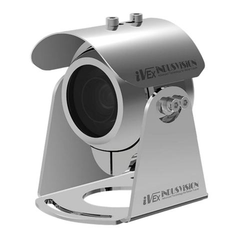
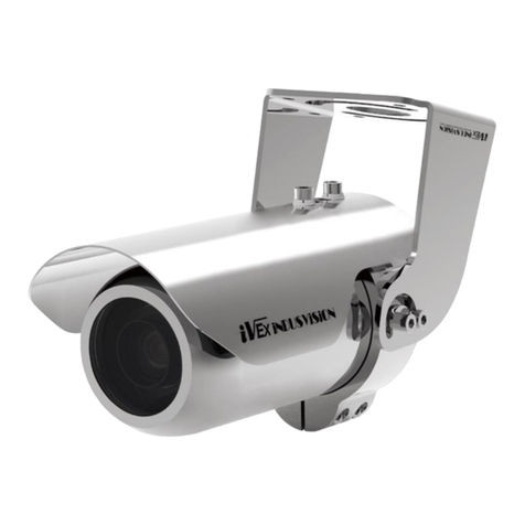
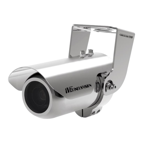
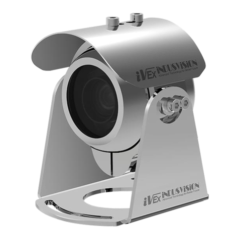
iVex Indusvision IVEX-FZ User manual

IVEX-FZ User Manual
Explosion proof Security Camera
Be sure to read this manual before installing or using the product.

02
1. Safety Instruction
2. Typical Features
3. Components
4. Part Names
5. How to Install
3
4
5
5
6
5-1. Separating a front Cover from Housing Body
5-2. Installing a Camera into the Housing
5-3. Main Board Configuration
5-4. Main Board Setting
5-5. Connecting Main Board
5-6. Basic Installation
5-7. Cable Configuration
6. Checklist Before Installation
7. Specifications
8-1. Dimension
8-2. Dimension
6
7
8
9
10
11
12
13
14
15
16
Address IP : 192.168.1.2
ID/Password : root / pass
If you install a camera not manufactured by INDUSVISION,
the default IP and ID / Password may be changed.
Contents

03
1. Safety Instruction
1. Install and use this system after reading these safety instruction thoroughly.
2. Keep these instructions after reading.
3. On installing this product, use all kinds of screws and bolts made of stainless steel to
asten the mount to outdoor surfaces and have to use explosion proof certified
accessories for installing.
4. Only use replacing parts recommended by the manufacturer.
5. The maximum ambient temperature range is -40℃ to 67℃ (-40℉ ~ 152.6℉).
6. Refer all servicing to qualified service personnel. Servicing is required when the apparatus
has been damaged in any way, such as power supply cord or plug is damaged,
liquid has been spilled or objects have fallen into the apparatus, the apparatus has been
exposed to rain or moisture, does not operate normally, or has been dropped.
7. The weight of the product is heavy, so be careful when lifting the product. It is highly
recommended to wear non-slip gloves during installation.
8. Receiving this product before installation, please check the system and working according
to the “chapter 7. checklist before installation”
CAUTION
TO REDUCE THE RISK OF ELECTRIC SHOCK.
DO NOT REMOVE COVER(OR BACK). NO
USER SERVICEABLE PARTS INSIDE REFER
SERVICING TO QUALIFIED SERVICE
PRERSONNEL
CAUTION
RISK OF ELECTRIC SHOCK
DO NOT OPEN
WARNING : This symbol indicates that dangerous voltage constituting a risk
of electric shock is present within this unit.
WARNING : Do not open when an explosive atmosphere may be present.
WARNING : To reduce the risk of ignition of hazardous atmospheres,
disconnect the equipment from the supply circuit before
opening. Keep assembly tightly closed when operating.
WARNING : To reduce the risk of ignition of hazardous atmosphere, all
conduit runs must have sealing fitting or cable gland placed
within 3/4”of the enclosure.
WARNING : Do not open when an explosive atmosphere may be present.
04
2. Key Features
IVEX-FZ Type
• Ex Certification : IECEx / ATEX / KCs / NEPSI / CE / FCC / KC
• Ex Grade : Ex d IIC T6 Gb. Zone 1 & 2, Ex tb IIIC T85˚C Db. Zone 21 & 22
• AISI 316L Stainless Steel Construction
• IP67 Protection Degree
• Germanium Glass, Protection Grid(FZ-40/41) / Fully Tempered Glass
• Operating Temperature : -40°C ~ +67°C
• Operating Humidity : Less than 90%RH
• Pan/Tilt Travel Range : ±60º(Manual) / ±45º(Manual/Protractor)
• Cable Outlet : 1 EA(NPT 3/4“)
• Option : Wiper / Fan / Heater / Window defroster
• Support RS-485 Protocol
• ONVIF Support
This Product is Equipped with a Protractor to
Allow Manual Rotation of 60 Degrees left and
Right and 45 Degrees Up and Down, and a
Built-in Camera for Viewing Images.
Sunshield Protects the Product From Damage
Caused by Radiant heat or rain.
A Wiper is Mounted on the Front of the Camera
Window to Maintain a clean image.

05
3. Components
1. Camera 2. Sun-shield 3. User’s Manual
4. Part Names
1. Camera Housing Cover
2. Camera Housing Body
3. Sun-shield
4. Accessories 5. SMPS(Power supply) 6. Connecting Cable
(3)
(5)
(2)
4. Cable Entry, NPT 3/4 inch
5. Protractor
(1)
(4)

06
5. Installation
5-1. Separating a Front Cover From Camera Housing
1 2
3 4
Sunshield Remove the top two M5xL10 bolts to
Separate the sunshield from the housing body.
Remove all eight M5xL20 bolts from the front of
the housing cover using a hexagonal wrench(4mm).
(A) Turn two bolts M4xL40 in the accessory pack
to the clockwise with a balance then the screw
bolts push the cover from the housing.
Separate the front cover from the housing body
carefully.
M5 X L10
(Spring Washer + Flat Washer) 2set M5 X L20
(A)
(A)
M4 X L40
(B)

07
5. Installation
5-2. Assembling Camera into the Housing
1 2
3 4
Assemble the camera to the slide bracket of the
Camera with a supplied M6 x L6 bolt
Assemble the sliding bracket having a
Camera loosely with supplied four H3 x L8 bolts to
A temporary position on the main bracket
After sticking a lens of the camera to the front
Tempered glass, tighten the main bracket of the
camera with four M4 x L10 bolts
M6 x L6(Spring Washer) 1set
H3 x L8
(Spring Washer) 4set
Camera
Main Bracket
Mount Bracket for BOX Camera

MAIN BOARD
08
5. Installation
5-3. Main Board Configuration
MAIN BOARD
MAIN BOARD
No Name No Name
1Data Communication (RS-485)
Port_2 Pin (2port) 9Wiper Motor Power Port_2 Pin
2Main Input Power Port(DC12V)_2 Pin
Camera Output Power (DC12V)_2 Pin 10 Temperature Sensor Port_2 Pin
3Wiper Sensor Port_3 Pin 11 Heater Power Port_2 Pin
4Relay AUX Port_3 Pin 12 Fan Power Port_2 Pin
* Caution : On input power to Main power port (No.2), it needs to supply enough currents
power to work for main board and camera at the same time.
Ex) On working for Camera, Wiper, Fan, Heater at the same time, needs DC12V, 2.5A.

09
5. Installation
5-4. Main Board Setting
Function Setting and Functions
No. 9.
Selectable
Board
Rate
10.
Address
Setting
Factory
Default
Wiper On : 85 + Preset, Off : 69 + Preset
Relay
Output
(Aux)
On : 86 + Preset, Off : 79 + Preset
Fan/
Heater
Fan : On, if the inside temperature is more than 30°C & heater working
Heater : On, if the inside temperature is less than 5°C
The Address can be set No. 0 to No. 99
The left switch (SW#1) is tenth digit and right switch (SW#2) is unit digit in the both rotary switches
Ex)

10
5. Installation
5-5. Connecting Main Board
RS-485 TX(2Pin) Input Main Power(2Pin)
Input zoom
Camera(2Pin)
Wiper Sensor(3Pin)
Fan(2Pin)
Heater(2Pin)
Temp. Sensor(2Pin)
Wiper Motor(2Pin)
AUX(Relay)(3Pin)

11
5. Installation
5-6. Basic Installation
1. (A) Please check the status thread of the nut if there is dusts or regular condition for hex.
Stainless steel bolt or wrench bolt (M8x1.25Px20L) and fix it with washer/spring-washer to keep
locking the bolts on the product.
2. According to the environment, it can be changed brackets
(to be Wall Mount Type or Pedestal Type), (refer to the “Chapter.8 Dimension”)
3. (B) Check the thread of the sealing fittings if there is dust or good status for using.
4. (C) Connect a nipple with thread of cable entry and tighten flexible cable in the sealing fitting.
In here, all cables have to come out though sealing fitting and all of sealing fitting, cable grand,
and flexible cable must be certified the explosion proof standards.
[C]
[B]
[A]
NPT 3/4“-14 Cable grand
Ex-proof Sealing fitting
Filter Finishing material Cable
(M8 x 1.25P x 20L) x 4 set
NPT 3/4”-14
Nipple(including)
NPT 3/4“-14
Sealing fitting
(Non-including)
Ex-proof
Flexible cable
(Non-including)

MAIN BOARD
12
5. Installation
5-7. Cable Configuration
3M ±0.2
Wire Color Function Description
Red
Black
Power Input
(DC 24V)
+
-
*Black
(UTP) HD Video/Data RJ45
Black/Brown
Red/Orange Control Data RS485 Data +
RS485 Data -
Yellow Analog Video out BNC
Power(DC24V)
Network(RJ45)
Data(RS-485)
Video(BNC)

13
6. Checklist Before Installation
No. Check Point Check
1Please use the power supply (SMPS) that is supplied from factory or your
provider and be careful to connect specification of the power supply.
(DC24V, AC220V / AC110V)
2Please connect exactly polarity (+/-) of the Data Cable (RS-485).
3Please check the video quality by connecting video cable(BNC Connector)
to DVR or Monitor.
4After connecting CAT. 5 cable (RJ-45 Jack) to network port, please check the
video, data control and other conditions in the normal network condition.
5Please set the protocol and baud rates as following:
- Protocol/Baud Rate : Pelco-D / 9600 bps
- ID Address : No. 1 (Default)
6In IP Network Camera, please set and save exactly PELCO-D, 9600 bps and
ID Address in the supplied CMS or NVR software.
7Check WIPER operation (Left/Right)
(Press No.85 and Preset-key: ON, Press No. 69 and Preset-key : OFF)
1. When you receive, please check the product according to the following checklist before
installation in the site and if you find the normal for all, please install the goods.
2. Please be noted it could be charged for some service if you don’t remind the checklist.
out of check list.)
INDUSVISION INC / CS Technical Team : +82-32-623-0750

14
7. Specifications
CAMERA SPECIFICATION
Model IVEX-FZ Series
Ex Certification IECEx / ATEX / KCs / NEPSI / CE/ FCC / KC
Ex Grade Ex d IIC T6 Gb, Zone 1 & 2
Ex tb IIIC T85˚C Db. Zone 21 & 22
Material AISI 316L Stainless Steel
Window Material Germanium glass, Protection Grid(FZ-40, 41) /
Fully Tempered Plate Glass
Protection Degree IP67
Operation Temperature -40°C ~ +67°C
Operation Humidity Less than 90%RH
Communication RS-485
Pan/Tilt Range ±60º(Manual) / ±45º(Manual/Protractor)
Lens(FZ-30) F= 7mm ~ 84 mm / F1.5(wide) ~ F1.9(tele)
Cable Outlet 1 EA(NPT 3/4”)
Fan/Heater Option
Power Consumption Approx. 50 W
Power DC 12V, 50/60Hz
Size 172(W) x 235(H) x 380(L)mm
Weight Approx. 10 kg

15
8-1. Dimension
DIMENSION
Unit : mm

16
8-2. Dimension
IVEX-FZ-WB
Unit : mm
Table of contents
Other iVex Indusvision Security Camera manuals

iVex Indusvision
iVex Indusvision IVEX-PLs-3101R User manual

iVex Indusvision
iVex Indusvision IVEX-PLs-3001R User manual

iVex Indusvision
iVex Indusvision IVEX-PL-3111R User manual

iVex Indusvision
iVex Indusvision IVEX-PL-3011R User manual

iVex Indusvision
iVex Indusvision IVEX-PLs-3001S User manual

iVex Indusvision
iVex Indusvision IVEX-PTZ Series User manual

iVex Indusvision
iVex Indusvision IVEX-PTZ-A Series User manual