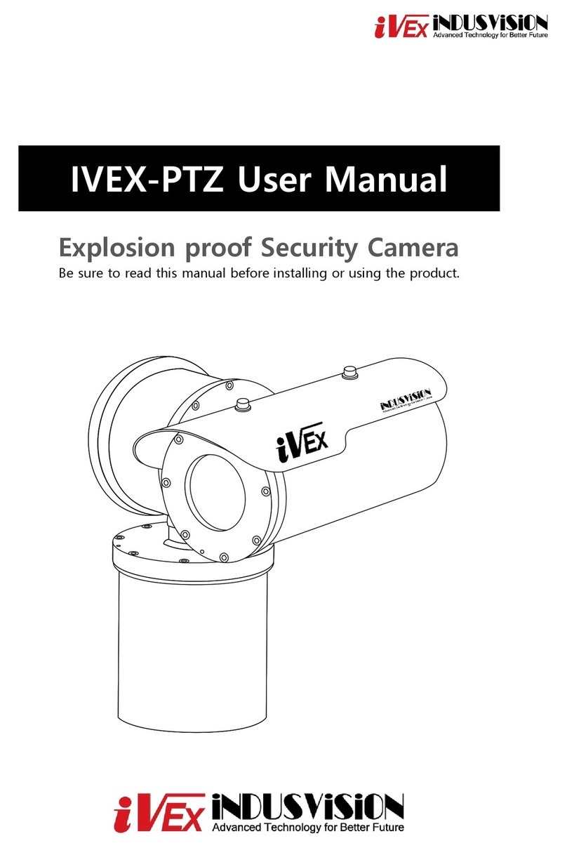
iVex Indusvision IVEX-PTZ-A Series User manual

IVEX-PTZ-A Series
IVEX-PTZR-A Series
http://www.indusvision.com
User Manual

01IVEX Series Explosion Proof Camera Manual
IVEX-PTZ-A Series
IVEX-PTZR-A Series
User Manual
Copyright
©2021 INDUSVISION Inc. All rights reserved.
Notes on the use of copyrights and trademarks
The names of products and companies mentioned in this manual are trademarks
or registered trademarks belonging to the company. It is a trademark.
Warranty
If the product does not operate properly even though the product is operated under normal
conditions of use, The manufacturer will repair it for free.
The warranty period is 2 years and the following circumstances are excluded from the warranty.
1. When the system operates incorrectly by executing a program not related to the system operation.
2. Changes in the product over time or abnormalities caused by natural wear during use.
※Product appearance and specifications are subject to change without prior notice to improve performance.
Every 3 months to protect personal information safely and prevent personal information theft damage
Change your password periodically.
Users are responsible for security and other issues caused by careless password management.
Be very careful.

02IVEX Series Explosion Proof Camera Manual
목차
Summary
03
04
05
07
09
12
16
18
21
22
23
25
27
•Components
•Part names
•Safety Rules
•Identification method
•Precautions before installation
•How to Installation
•Camera self-installation
•NETWORK setting
•Firmware update
•Maintenance
•Troubleshooting
•Technical drawing
•Product warranty
PC system recommended specifications
•CPU : Intel Core 2 Duo 2.4 GHz or more (1920x1080 30fps Use)
Intel Core i7 2.8 GHz or more (1920x1080 60fps Use)
•Resolution : 1280x1024 or more (32 bit color)
•Memory : 2GB or more
•Supported OS: Windows XP, VISTA, 7, 8, 10 / Mac OS 10.7 more
•Support web browser: Microsoft Internet Explorer (Ver. 8~11),
Mozilla Firefox (Ver. 9~19) New 85
Google Chrome (Ver. 15~15) New 88
Apple Safari (Ver. 6.0.2) New 14
-Windows 8 is only supported in desktop mode.
-Beta or developer versions other than those released on the
official website are not supported.
-Windows 7 or higher is recommended for IPv6 connection.
-Safari Browser is only supported on Mac OS X.
•Video memory: 256MB or more
-If the driver of the video memory card is not installed correctly or
is not the latest version, the video may not play properly.
-If more than one monitor is used, playback performance may decrease
depending on the system specifications.

03IVEX Series Explosion Proof Camera Manual
*2
*1
*1
*1
*1 *1 *1 *1
*1
별도 구매품
*1 *2
+
M5 M4 M3 M2.5 M1.5
*1
M4*8
M4*40
M8*15 SET 0.75W
Basic Components
Components
Before starting the installation,
remove the following components enclosed in the product box.
Please check carefully to ensure that there are no missing parts during
installation.
SMPS
Sun shield Multi cable User Manual
Cable gland L wrench set Wrench bolt
Plug
Hex Bolt Set Lug
Cross bolt RJ-45 socket
Pedestal mount
or
Wall Bracket Set Anchor
•Cable glands and plugs may not be provided or may be replaced
with sealing fittings depending on some models.
•Sun shield is provided only for IVEX-PTZ-A Series.
(IVEX-PTZR-A Series is installed on the product and shipped.)
•SMPS is provided in 24V for IVEX-PTZ-A and PTZR-A series.
•The camera sponge and camera mount SET are exclusive
accessories for the PTZ-31-A.
•When purchasing pedestal mount and wall mount bracket,
set anchor 4EA or 6EA is provided as standard.
Component Notes
L Wrench (Hexagonal) Standard
M5
M4
M2.5
M1.5
M4(Cross bolt)
M5
M3

04IVEX Series Explosion Proof Camera Manual
IVEX-PTZR-A Series
IVEX-PTZ-A Series
①Camera Housing Cover
②Camera Housing Body
③Sun Shield
④Tilt Flange
⑤Tilt Body
⑥Tilt Cover
⑦Pan Flange
⑧Pan Entry
⑨Pan Cover
⑩Cable Entry, NPT ¾” *2
⑪Pan Body-PB
①
②
③
④
⑤
⑥
⑦
⑧
⑨⑩
⑪
①
②
③
④
⑤
⑥
⑦
⑧
⑨
⑩
⑪⑬
⑫
①Camera Housing Cover-R
②Camera Housing Body-R
③Sun Shield
④Tilt Flange-R
⑤Tilt Body
⑥Tilt Flange-L
⑦Camera Housing Body-L
⑧Camera Housing Cover-L
⑨Pan Flange
⑩Pan Entry
⑪Pan Cover
⑫Pan Body-PB
⑬Cable Entry, NPT ¾” *2
Part Names
Part names for each product are important to provide fast and accurate
service for each part, so please be aware of it.

05IVEX Series Explosion Proof Camera Manual
Safety rules
Please read the product instruction manual carefully before installing and
using this product.
Keep the manual in a separate place for future reference.
•This product must be installed and maintained by qualified
personnel according to national standards such as
EN/IEC 60079-14, EN/IEC 60079-17, etc.
•Do not open the product with power applied in the
explosion-proof area.
•Installation of the product should be carried out using suitable tools.
•The manufacturer recommends the use of explosion-proof tools.
•Connection testing and maintenance work in non-hazardous areas
is recommended.
•Grounding is essential to reduce the risk of ignition of
products installed in explosive environments.
•The device must be connected to a protective earth.
•At this time, it is recommended to use an approved material for
the grounding cable.
•Before turning on the product in a potentially explosive location,
make sure that the connections, such as cable glands,
are properly closed.
•When the surface temperature of the device rises due to direct
sunlight exposure, the surface temperature rating of the device is
judged only by the ambient air temperature without taking into
account direct sunlight.
•Make sure all devices are certified for the application and the
environment in which they are installed.
•Any changes not approved by the manufacturer are not guaranteed.
Danger of explosion
Be sure to read this to reduce the risk of explosion.
•When installing or performing maintenance while the breaker is ON,
Make sure the product is turned off.
•The power-off device must be included in the electrical installation,
ensuring that it is recognizable very quickly and turns off when
necessary.
•For the electrical installation to which the device is connected,
a maximum of 16A earth leakage breaker is recommended.
The minimum spacing between circuit breaker contacts should be
3 mm (0.1”).
•Do not use worn or corroded cables.
•During installation and operation, check whether the characteristics
of the power supply provided by the facility match the characteristics
of the power supply required by the product.
•This product is not suitable for use in locations where children
may be present.
Risk of electric shock
To avoid the risk of electric shock, make sure that voltage
is applied to the product before performing any work.

06IVEX Series Explosion Proof Camera Manual
•Make sure the installation method meets the explosion protection
regulations and specifications.
•After connection, it is recommended to test and install in
a non-explosion-proof area before installing in the field.
•Use a suitable cable that can withstand the operating temperature.
•All unused cables must be electrically insulated.
•This product can only be installed in a standard location.
•Make sure the device is securely fixed before applying power.
•When the power is turned on, this product performs several
automatic calibration/inspection tasks.
Do not stand near the device when power is applied.
•Unauthorized modification, use of non-genuine spare parts,
and unauthorized modification by the manufacturer.
We are not responsible for any damage to the equipment caused
by installation, maintenance and repair by unskilled personnel.
•For technical service, refer only to qualified technicians.
•This product should only be repaired by trained personnel
or under the supervision of the manufacturer's personnel.
•When repairing, use only genuine Indusvision parts.
•Strictly follow the maintenance instructions given in these
operating instructions.
Caution when working
Operation is very important for the correct functioning of
the system. Please proceed with the installation
in the order indicated in the product instruction manual.
Safety rules
Please read the product instruction manual carefully before installing and
using this product.
Keep the manual in a separate place for future reference. •Considering the characteristics of the product, use an appropriate
transport and handling system.
The installer must comply with general accident prevention standards
when handling the product.
•Before proceeding with the installation, compare/check with the
components in the user's manual to check whether they match.
•Equipment installation in hazardous areas is carried out by
specialized technical personnel.
•The manufacturer assumes no responsibility for any damage arising
from improper use of the devices mentioned in this manual.
We also reserve the right to change some parts without mentioning.
•The manufacturer does not accept any responsibility arising from
improper use of the device.
•Since it is the user's responsibility to select the surface on which
the product will be fixed, no fasteners are provided to attach the
product to a specific surface.
It is the responsibility of the installer to select a fixture suitable
for that particular application.
Use installation methods and materials that can support at least
four times the weight of the product.
•Contact the manufacturer for exact explosion-proof joint dimensions
information.
•For all product maintenance, it is recommended that the product be
repaired by sending the product to the manufacturer.
•This product is controlled remotely, and movement may occur during
operation.It must be installed so that no one is injured by moving
products. Be careful not to hit other objects or create a dangerous
situation while the product is moving.
•This is a Class A product. In residential environments,
this product may cause radio interference.
In this case, a suitable electromagnetic shielding method may be
required by the user.
•It is recommended to use an uninterruptible power supply (UPS)
in case of a temporary power outage.
Product feature description
Please read the information below to understand the
installation process.
07IVEX Series Explosion Proof Camera Manual
①
②
③
④
⑤
⑥
⑨
⑩
⑦
⑧
[KOR Ver.] [ENG Ver.]
①
②
③
④
⑤
⑥
⑧
⑦
⑨
⑩
Product specification inspection
Identification method
①Precautions
②Manufacturer and address
③Model name
④Serial number: It consists of a 9-digit system excluding the
model name, and the 6 digits from the left mean
the year, month, and day of production, and
the 3 digits after that represent the product No.
assigned to that year.
⑤Rated operating voltage: It means the rated voltage of the product,
and Class3 =15W.
⑥Operating temperature: ambient temperature
(-25˚C≤Ta≤+65˚C, -25˚C≤Ta≤65˚C or Tx˚C)
⑦T Class (Tx or Tx... Tx)
⑧Maximum surface temperature (Tx˚C or Tx˚C... Tx˚C)
⑨Safety certification issuing organization
⑩Safety certification number
Certification IVEX-PTZ, PTZR Series Certification Number
IECEx IECEx KGS 14.0001X
ATEX KRH 14 ATEX 1013X
NEPSI GYJ14.1418X
KCs 14-GA2BO-0288X
16-GA2BO-0166X
20-GA2BO-0560X~0565X
IK IK10 : 19-079699-01-1

08IVEX Series Explosion Proof Camera Manual
Single Lineup
IVEX-PTZ-A Series
Dual Lineup
IVEX-PTZR-A Series
Tempered glass only
-IVEX-PTZ-30A, 31A
-IVEX-PTZR-40A, 41A, 44A
Tempered glass + wiper
-IVEX-PTZ-30AW, 31AW
-IVEX-PTZR-40AW, 41AW, 44AW
Tempered glass + infrared LED
-IVEX-PTZ-30AIR, 31AIR
-IVEX-PTZR-40AIR,41AIR, 44AIR
Germanium glass only
-IVEX-PTZ-41A, 44A
-IVEX-PTZR-41A, 44A
Tempered glass + wiper + infrared LED
-IVEX-PTZ-30AWIR, 31AWIR
-IVEX-PTZR-40AWIR, 41AWIR, 44AWIR
Identification method
The explosion-proof certification number may change depending on the
manufacturer's product upgrade status.
Therefore, please refer to the manufacturer's website for exact specifications.
Classification by model
•The selection of glass cover types for each product line can
be combined with the glass types listed on the left.
•Please contact the manufacturer for details.

09IVEX Series Explosion Proof Camera Manual
Check the packing box
!
Precautions before installation
Before proceeding with the installation of the product, carefully read the
chapter'Safety Rules' in the product manual.
Information provided on the
box label
-Model name
-Serial number of the product
-IP address
-ID / Password
-etc
•When delivering the product, check that the packaging is intact,
and that there are no drops or tears.
•In the case of returning a broken product, it is recommended
to use the packaging box provided for transportation.
•The box label affixed to the product box contains the information
shown above. Before discarding the box, please back up the
information entered on the label to prevent product operation
problems.
Check the contents
•Refer to the component information on page 3 and check that
the contents match.
Safe disposal of packaging materials
•Among the packaging materials, PE foam other than paper is
subject to separate discharge.
Therefore, please separate and dispose according to the
separate collection method and regulations.
Check before installation
•It is recommended to use only the brackets and accessories
approved by the manufacturer for the brackets required for
installation.
•The manufacturer is not responsible for any damage caused
by the use of brackets not provided by the manufacturer.
How to install
•This system can only be installed in a standard location.

10IVEX Series Explosion Proof Camera Manual
Mounting and fixing to the pole
Before proceeding with the installation of the product, carefully read the
chapter'Safety Rules' in the product manual.
Fixed to vertical wall
Pedestal mount
•Using the provided hexagon bolt SET, fasten the bolts to the
bolt hole between the pedestal mount and the product.
•At this time, check that there are no foreign substances in
the thread or the product's fastening hole.
•Before tightening the bolts, apply enough locking compound
(Loctite 263, medium-strength thread locker) to the bolting holes.
•The thread compound should solidify for an hour, during which
time the installation should be completed.
•Fix the assembled device to the railing or ceiling using the hole
outside the adapter. Use screws that can withstand at least four
times the weight of the device.
•When tightening the bolts, tighten the torque to 35Nm.
Set anchor
Bracket from top to bottom
•The wall mount bracket can be fixed to a vertical wall.
•Fix the bracket to the wall with the provided set anchor that
can withstand at least 4 times the weight of the device.
Then use the provided hexagon bolt SET to fix the device
to the bracket.
•At this time, check that there are no foreign substances in the thread
or the product's fastening hole..
•Apply enough locking compound (Loctite 263) on the two screws
and lock the screws.
•The thread compound should solidify for an hour,
during which time the installation should be completed.
•When tightening the bolt, tighten the torque to 35Nm.
Precautions before installation

11IVEX Series Explosion Proof Camera Manual
Removal of PE foam for fixing TILT
Before proceeding with the installation of the product, carefully read the
chapter'Safety Rules' in the product manual.
Fastening of the sun shield
PE foam for fixing TILT
Remove
•After confirming that the product is firmly fixed to the bracket
or flat surface, be sure to remove the PE foam for TILT
fixing.
•Applying power without removing the PE foam for TILT fixing
may cause product failure.
•When the sun shield provided as an accessory is shipped from
the factory, fix the wrench bolt (M6 SET) fastened to the top of the
housing using the L wrench (M5) to the housing.
•Before bolting, apply enough locking compound (Loctite 263)
to the bolting hole.
•The thread compound should solidify for an hour,
during which time the installation should be completed.
•When tightening the bolts, tighten the torque to 15Nm.
Precautions before installation

12
Open connection
•Loosen the M3 tanning bolts in the position ①on the top and bottom
of the device using an L wrench (M 1.5).
At this time, be careful not to lose the tanning bolt.
•The tanning bolt is used to prevent the PAN Cover from loosening.
•Remove the PAN Cover by turning it firmly by hand as shown
in the picture in ②.
•When removing the PAN Cover, be careful not to damage the thread
and O-rings.
•Remove 2EA of the protective plug for the input part of the
NPT cable of ③by hand.
-Keep the protective plug at the input of the NPT cable for
future service.
①
②
③
③
IVEX Series Explosion Proof Camera Manual
How to Installation
It is strongly recommended that all devices be carried out after final testing
prior to installation at the final installation site.
Ground installation method
•M4*8 Cross bolt
•M5 Lug
•The product must be grounded with an external cable
(16AWG) with a 4mm² cross section.
•Use the ground lug provided with the product and
M4*8 (Cross bolt) screws to fix the lug to be used for
power connection to the grounding hole with the L wrench
provided.
•A separate press is required to press the lugs.
•At this time, the presser is not provided separately.

13
•In the case of the cable gland, it is screwed into the NPT ¾ hole
of the device. At this time, do not tighten hard to enter the cable.
When the cable entry is complete, tighten it with a
monkey spanner.
•At this time, apply enough locking compound (Loctite 263)
to the fastening holes.
•Tighten the opposite side of the unused part in the same way as
the cable gland fastening method using the enclosed plug.
•In the case of sealing fitting, fasten the NPT ¾ nipple of ①first,
and then fasten the sealing fitting of ②to the opposite side
of the nipple. Next, when cable entry is complete,
a compound (pipe sealant) is injected to close the inside
of the sealing fitting.
•At this time, apply enough locking compound (Loctite 263)
to the fastening hole.
•Use the enclosed plug (③) on the opposite side of the unused
part to tighten it in the same way as the sealing fitting.
①
②
Loctite 263
③
Loctite 263
①
②
IVEX Series Explosion Proof Camera Manual
Sealing fitting connection
It is strongly recommended that all devices be carried out after final testing
prior to installation at the final installation site.
Cable gland installation method
•When using the sealing fitting,
it is possible to use it normally
when the inside of the sealing fitting
is finished with a compound
as shown in the picture.
How to Installation

14
Cable entry
Connector connection
•Insert the cable from the outside of the device to the inside of
the PAN Cover as shown in the figure.
•Be careful not to damage the sheath of the cable core wire
when entering.
•Remove the core wire protection tape after entering the cable.
•For connector connection, refer to 'Connector Connection’
on the right.
After disassembling the cable gland by parts, insert the cable.
Power(DC24V)
Network(RJ45)
Data(RS-485)
Sensor In
①
②
③④
⑤
⑥
⑦
⑧
No. Detailed function
1RJ-45 NETWORK INPUT
2RS-485 & ALARM INPUT/OUTPUT
3DC-24V INPUT
4DC-24V OUTPUT
5ADDRESS *10 UNITS
6ADDRESS * 1 UNIT
7RELAY 1,2,3
8FUNCTION SW
IVEX Series Explosion Proof Camera Manual
485+
485- X1
It is strongly recommended that all devices be carried out after final testing
prior to installation at the final installation site.
How to Installation

15
Closing the junction box
•When the cable installation and the explosion-proof flexible
installation are completed, close the PAN Cover of ①as shown
in the figure.
•Before closing the PAN Cover, check that there are no foreign
substances on the lid.
•Lubricate the threads with grease conforming to IEC/EN60079-14
so that the PAN Cover can be closed smoothly.
•When closing the threaded PAN cover in the junction box,
arrange the cables so that they do not get in the way.
•Turn the PAN Cover with the screw thread of the junction box
by hand until the O-ring is not visible.
•Tighten the M3 tanning bolts of ②and ③using the L wrench
(M1.5) included with the product.
(At this time, the PAN Cover of ①must be locked as far as possible)
•After all installation is complete, install the product and enclosed
SMPS inside the explosion-proof enclosure, and install necessary
devices such as network and other RS-485 controllers.
•Carefully connect +,-of the DC-24V power supply and apply
the power.
•Carefully check all connections to the product before applying
power.
•When power is applied, the system goes into a warm-up
state and automatically checks all items related to PAN/TILT
and camera.
•At this time, if there is no abnormality during the inspection,
it is connected to the network and it is in a state that can be
used normally.
•Immediately after detecting an abnormality in the initial state,
turn off the power and contact the manufacturer.
②
①
③
DC24V
NETWORK
etc.
IVEX Series Explosion Proof Camera Manual
220V GND 24V-24V+
It is strongly recommended that all devices be carried out after final testing
prior to installation at the final installation site.
SMPS connection in explosion-proof
enclosure
How to Installation

16
②③
①
IVEX Series Explosion Proof Camera Manual
①
③
④
②
Camera self-installation
Open Camera Housing Cover
When replacing or installing the camera, be sure to work in a safe area
outside of the explosion-proof area.
•For camera mounting, remove and store 8EA of M5*10
wrench bolts on the camera housing cover using L wrench (M4).
•To open the camera housing cover of the product,
use the M4*40 wrench bolt provided as a component as shown
in ②and fasten it to the 2 points of M3 thread.
•Tighten two M4*40 wrench bolts with an L wrench (M3) alternately,
so that the camera housing cover is little by little away from
the body.
•When a certain part of the camera housing cover is far from
the body, pull the camera housing cover by hand as shown
in ③to completely separate the camera housing cover.
IVEX-PTZ, PTZR Series Mounting of other
companies' cameras and connecting cables
Connected to
the Tilt part
※Offset Bracket installation
required according to camera height
•As shown in ①, check if the camera is aligned with the
camera housing cover. If the height is low, use the Offset Bracket to
match the height and mount it on the IP bracket.
Otherwise, place the camera directly on the IP bracket.
•As in ②, use a Phillips screwdriver to match the mounting hole
of the camera and fasten it.
•Connect the 30Pin Cable to the main board as shown in ③.
(Separation can be done in the reverse order of fastening.)
•As shown in ④, pay attention to the cable and put the direction
into the camera housing body and assemble in the reverse order
of disassembly.

17IVEX Series Explosion Proof Camera Manual
Related to the installation of third-party
cameras on the IVEX Series
•When a third-party camera is mounted, the manufacturer excludes
the camera part except for the housing body and its moving body.
•Therefore, the user is responsible for all use of a third-party camera,
and refer to the third-party camera manufacturer's manual for
information on camera setting manual and IP setting.
When replacing or installing the camera, be sure to work in a safe area
outside of the explosion-proof area.
Camera self-installation

18IVEX Series Explosion Proof Camera Manual
Web browser access
①In Internet Explorer's address bar, enter the IP address
you checked in ‘Checking the packaging box’ on page 10.
②When the web page shown in the picture above appears,
enter your ID and PW, and click the OK button.
③If you log in successfully, you will be taken to the system
settings page.
How to connect for the first time in
Google Chrome
①
②
③
admin
1234
Input new PW
NETWORK setting
After sufficiently checking the IP-related information that can be checked in
‘Checking the packing box’ on page 10, proceed to the following.
The connection is not set to private.
Hacker may betrying to steal information(ex: password,message, creditcard, etc.)
from 192.168.10.100Learn more
Advanced Click
Help us improveSafe Browsing by sendingsome system informationand page content to Google.
Privacy Policy
Return to safety page
Live System setting
Server 10.20.30.40 is requesting username and
password.
That server also reports "GoAhead".
Remember my credentials
Confirm Cancel
Windows s ecurity
Caution
Privacy error
Chrome is not set as the default browser. Set as default browser
D
It cannot be verified that this server is 192.168.10.100,
and it is not a security certificate trusted by the computer operating system.
This may be because the server is configuredincorrectly,
or an illegal user is interceptingthe connection.
Go to 192.168.10.100 (not secure) Click
admin
1234 D
Login
Input new PW

19IVEX Series Explosion Proof Camera Manual
IP address change
•When selecting Fixed IP in IP setting, all settings except
DNS must be entered in the setting window as shown in the
figure above.
•At this time, the gateway of the PC to which the router
and web viewer are to be connected must match the camera.
•The IP address must also match the camera with all numbers
except for the 4th digit address, such as 192.168.1.X.
•It takes about 30-40 seconds for the settings to be applied.
If you do not want to apply the changed contents, you can
cancel the changed contents by clicking the Back button.
•Dynamic IP (DHCP) setting does not require the above IP setting.
Change Web Port
•Go to Basic Setting → IP Address.
Service
IP Address 192.168.1.20
Subnet Mask 255.255.255.0
Gateway 192.168.1.1
DNS 1 168.126.63.1
DNS 2 168.126.63.2
IPv4
Apply
Fixed IP Dynamic IP
HTTP
HTTP Enable
HTTP Port 80 (Default: 80, 80 ~ 65535)
HTTPS
HTTPS Enable
HTTPS Port 443 (Default: 443, 443 ~ 65535)
SHA256
SHA256 Enable
Used
Used Not Used
Not Used
Used Not Used
•Go to Basic Setting → Web Port.
Apply
Return
•The default setting of Web Port is as shown in the figure.
•The HTTP port is for web access, video streaming,
and playback.
•The HTTP port is the network port that the PC uses to access
the product's web page, and can be used by specifying a port
in the range of 80 to 65535.
The default is 80
•The above setting can be changed by the user,
but the port is a general setting, so the manufacturer is
not responsible for any problems caused by the change.
•SHA256: Set whether to use SHA256 encryption.
•Both HTTP Port and HTTPS Port cannot be set to Disable.
Either of them must be enabled.
NETWORK setting
This manual suits for next models
11
Table of contents
Other iVex Indusvision Security Camera manuals

iVex Indusvision
iVex Indusvision IVEX-PLs-3101R User manual

iVex Indusvision
iVex Indusvision IVEX-PL-3111R User manual

iVex Indusvision
iVex Indusvision IVEX-PLs-3001S User manual

iVex Indusvision
iVex Indusvision IVEX-PLs-3001R User manual

iVex Indusvision
iVex Indusvision IVEX-PTZ Series User manual

iVex Indusvision
iVex Indusvision IVEX-PL-3011R User manual

iVex Indusvision
iVex Indusvision IVEX-FZ User manual