IWAKI EK Series User manual

Read this manual before use of product
IWAKI
Electromagnetic Metering Pump
EK Series
Instruction Manual

Contents
IMPORTANT INSTRUCTION ....................................................... 1
Safety Instructions ........................................................................ 2
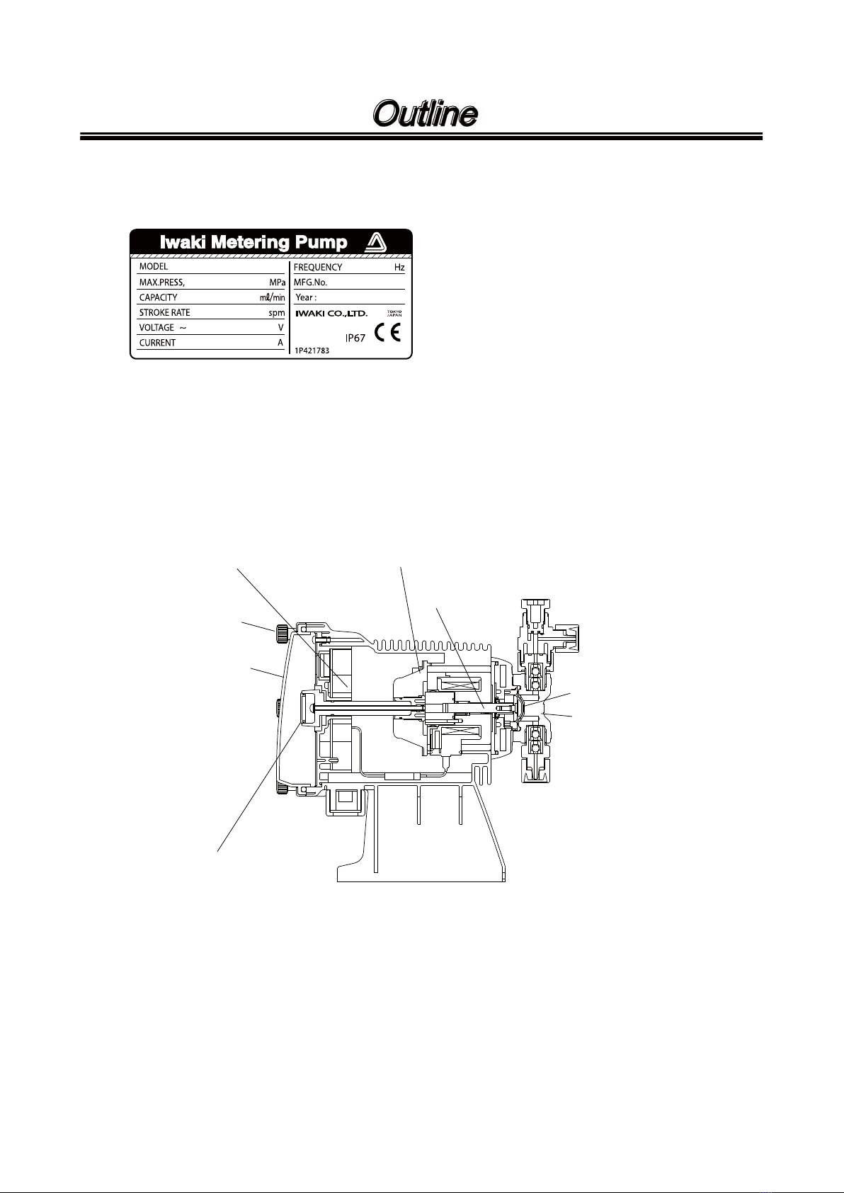
Outline........................................................................................ 5
1. Unpacking & Inspection ............................ 6
2.OperationPrinciple
................................... 6
3. Identification Codes
.................................. 7
4.Features
................................................... 8
5.MainParts
................................................ 8
6.Specifications
........................................... 9
7.OperatingFunction
.................................. 11
8.STOPFunction
....................................... 11
Installation .................................................................................. 12
1. Before Use
.............................................. 13
2.NotesonOperation................................. 13
3. Installation
.............................................. 14
4.Dimensions
............................................. 15
5. Piping
..................................................... 18
6.ElectricalWiring
...................................... 19
Operation ................................................................................... 21
1. Bleeding
.................................................. 22
2. Flow rate Adjustment .............................. 24
3.Operation
................................................ 25
4. Waterproof cover Mounting
..................... 29
Maintenance ............................................................................... 30
1. Troubleshooting
...................................... 31
2. Maintenance & Inspection ....................... 32
3. Wear Parts
............................................. 33
4. Disassembly & Assembly ........................ 34
5. Exploded View ........................................ 38
6. Accessories
............................................ 42
This instruction manual should be kept on hand by the end user for quick reference. It is
recommended that each user, after reading the instruction manual thoroughly, place it in a
position close to the pump system and where it may be easily accessed by any user at any
time whenever necessary.
Thank you for selecting the electromagnetic metering pump EK series. This instruction
manual deals with “Safety Section” “Product outline” “Installation Section” “Operation
Section” and “Maintenance Section”.
Please read through this manual carefully to ensure the optimum performance, safety and
service of the EK series.

- 1 -
Nonobservance or misapplication of the contents of
“Caution” section could lead to a personal injury or
damage to the product.
For the Safe and
Correct Handling of the pump
●"Safety Instruction" section deals with important details about handling of the product. Before
the use of the pump, read this section carefully for the prevention of personnel injury or loss.
●Observe the instructions accompanied with "WARNING" or "CAUTION" in this manual. These
instructions are very important for protecting pump users from dangerous situations.
●The symbols on this instruction manual have the following meanings:
WARNING
Nonobservance or misapplication of the contents of
“Warning” section could lead to a serious accident
which may result in death.
CAUTION
Types of Symbols
Indicates that “Warning” or “Caution” must be exercised. Inside this triangle, a con-
crete and practical image provided as a warning or caution message is depicted.
Indicates a prohibited action or procedure. Inside or near this circle, a concrete and
practical image of the activity to be avoided is depicted.
Indicates an important action or procedure which must be performed or carried out
without fail. Failure to follow the instructions herein can lead to malfunction or
damage to the pump.
Important Instructions

- 2 -
WARNING
CAUTION
●Turn off the power supply
Working without disconnecting the power supply may cause an electrical shock.
Before engaging upon any working procedures involving the pump, make sure to turn
the power supply switch off and to stop the pump and other related devices.
●Terminate operation
When you detect or become aware of a dangerous sign or abnormal condition during
operation, terminate the operation immediately and start it from the beginning again.
●For specified application only
The use of a pump in any application other than those clearly specified may result
in injury or damage to the pump. Use the pump strictly in accordance with the pump
specifications and application range.
●No remodeling
Never remodel a pump. Otherwise, a serious accident may result. Iwaki will not be
responsible for any accident or damage of any kind which is caused by the user
remodeling the pump without first obtaining permission or instructions from Iwaki.
●Do not submerge
The pump is not a submergible pump. Do not submerge the pump in the water or liq-
uid.
●Wear protectors
If you touch or come in contact with any type of hazardous chemical liquid, including
but not limited to chemicals, you may experience a serious injury. Wear protective gear
(protective mask, gloves, etc.) during the pump operation.
●Qualified operators only
The pump operator and pump operation supervisor must not allow any operators who
have little or no knowledge of the pump to run operate the pump. Pump operators
must have a sound knowledge of the pump and its operation.
●Specified power only
Do not operate the pump on voltage which is not specified on the nameplate. Failure to
do so may result in damage or fire. Only the specified power level is to be applied.
●Do not run the pump dry
Do not run the pump dry (without liquid inside the pump). Heat generated as a result of
abrasion between elements inside the pump during operation without liquid may dam-
age the inside of the pump.
No Remodeling
Prohibited
Electrical Shock
Prohibited
Prohibited
Prohibited
Prohibited
Wear protective
gear
Safety instructions

- 3 -
CAUTION
●Ventilate
Poisoning may result during an operation which involves toxic or odorous liquid.
Ventilate the operating site sufficiently.
●Damaged pump
Never operate a damaged pump. A damaged pump may cause leakage or electrical
shock.
●Do not damage power cable
Do not scratch, damage, process, or pull the power cable forcibly. An extra load onto
the cable, such as heating the cable or placing something heavy on the cable, may
damage the cable and finally cause a fire or an electrical shock.
●Arrange grounding
Do not operate the pump without connecting the grounding wire. Otherwise, an electri-
cal shock may result. Make sure the grounding wire is connected with the grounding
terminal.
●Install an earth leakage breaker (option)
The operation of a pump without using an earth leakage breaker may cause an electri-
cal shock. Please purchase an optional leakage breaker and install in the system.
●Handling of power cable
Use of a defective or damaged power cable may result in a fire or electrical shock.
Handle the power cable carefully.
●Follow the instruction manual
Replace the consumable parts by following the descriptions in the instruction manual.
Do not disassemble any part of the pump if the disassembling procedure for the part in
question is not included in the instruction manual.
●Limited operating site and storage
Do not install or store the pump in the following places:
* Places where a flammable gas or material is used or stored.
* Places where the ambient temperature is extremely high (50°C or higher) or extreme-
ly low (0°C or lower).
* Locations which receive direct sunlight.
* Locations subject to high temperatures and high humidity.
●Disposal of used pump
Disposal of used or damaged pumps must be done in accordance with the relevant
local laws and regulations. (Consult a licensed industrial waste products disposing
company.)
Prohibited
Electrical Shock
Prohibited
Electrical Shock
Caution
Grounding
Caution
Safety instructions

- 4 -
CAUTION
●Waterproof cover mounting
The waterproof property of IP67 is maintained as long as the waterproof cover is prop-
erly mounted. The waterproof cover has the direction for mounting. Do not mount it
upside down. The cover must be fixed securely with six thumb bolts.
If the pump is used without the waterproof cover or with the cover wrongly mounted,
the waterproof property of IP67 is not maintained resulting in pump failure. Water tight-
ness is not maintained either when the six bolts are not tightened securely.
●Frequent ON and OFF of pump must be done by STOP function (ON and OFF to
STOP terminal). If you are forced to stop and start pump by turning on and off
of power source, turning on and off must be limited to less than six times an
hour.
●Do not make key operation with wet hand
If the control panel gets wet and liquid enters the controller, the pump may malfunction.
Wipe the control panel immediately if it gets wet.
Safety instructions

- 5 -
1.Unpacking & Inspection ........................ 6
2.Operation Principle .............................. 6
3.Identification Codes ............................. 7
4.Features................................................ 8
5.Main Parts............................................ 8
6.Specifications ....................................... 9
7.Operating Function.............................. 11
8.STOP Function................................... 11
Outline

- 6 -
1. Unpacking & Inspection
After unpacking the pump, check the following
points to ascertain that the product is exactly
as you ordered. If you find anything wrong,
please get in touch with your dealer.
[1] Do the model, discharge pressure, voltage,
etc., shown on the nameplate represent
what you ordered?
[2] Has the pump been damaged in transit?
Are the bolts and nuts loose?
NOTE: The pump is not designed for
submergible use. Do not sub-
merge the pump in the water or
liquid.
Outline
2. Operation Principle
Bleed valve
Discharge port
Suction port
Diaphragm
Pump head
Electromagnet
driving unit
Pump shaft
Stroke length
adjusting dial
Control unit
Waterproof cover
Thumb bolt
With bleed valve
A pump shaft put in the electromagnet driving unit makes reciprocating movement which is brought by pulse
current from controller. This reciprocating movement is transferred to the diaphragm which open and close
by turns the discharge and suction valves to discharge the liquid. The speed of reciprocating movement
(stroke rate per minute) can be changed by changing the pulse frequency of controller. The length of recip-
rocating movement (stroke length) can be adjusted by stroke length adjusting dial to adjust the discharge
capacity per stroke. These two adjustments of stroke length and stroke speed enable fine adjustment of
flow rate.

- 7 -
Outline
3. Identification Codes
(Example)
EK - B 11 PC - 20E P R 2 -
(1) (2) (3) (4) (5) (6) (7) (8) (9)
(1) Pump Series
(2) Drive unit : B Average power consumption 20W
C Average power consumption 22W
(3) Diaphragm diameter (Nominal mm)
11: 10mm, 16: 15mm, 21: 20mm, 31: 30mm, 36: 35mm
(4) Wet-end material
1. PTFE is coated on EPDM for the material of diaphragm.
2. Material symbol PVC : Transparent hard polyvinyl chloride
GFRPP : Glass fiber reinforced polypropylene
CE : Alumina ceramic
HC : Hastelloy C 276
EPDM : Ethylene propylene diene methylene
FKM : Fluoroelastomer
PTFE : Polytetrafluoroethylene
PCTFE : Polychlorotetrafluoroethylene
(5) Power source
100 : AC100V/110V/115V 50/60Hz
20E: AC220V/230V/240V 50/60Hz
(6) Power cord
(7) Controller type R : R type
(8) Connection hose
(9) Special version code
Symbol Cord end
Press-fit terminal
With plug
No symbol
P
Symbol Hose diameter (mm)
4 × 9
4 × 6
6 × 8
8 × 13
9 × 12
Rc1/4” (Female)
1
2
3
4
5
10 × 126
9
Parts Diaphragm type
VC
PVC GFRPP
PTFE PTFE
PTFE PTFE
VH PC PH SH
SUS316
HC
SUS316
PTFE
–
PTFE
TC
PVDF
CE
FKM
PTFE
FKM
PTFE
CE HC CE HC
FKM EPDM FKM EPDM
FKM EPDM FKM EPDM
Pump head
Valve
Valve seat
Valve gasket
O ring
Diaphragm

- 8 -
4. Features
1) EK Series pump is a totally enclosed and water-proof construction (IP67 certified) type electromagnetic
metering pump. The waterproof property of IP67 is maintained as long as the waterproof cover is prop-
erly mounted.
2) The pump is water-proof construction and can be installed outdoor. Electronics parts and print circuit
board are moulded by plastic resin to avoid the deterioration by humidity.
3) Many kinds of control can be done easily because of CPU built-in controller. Touch key operation ena-
bles easy setting of stroke rate.
Automatic control by external pulse signal.
Pump can be stopped by external contact signal.
4) The waterproof cover prevents liquid from entering the controller.
5. Main Parts
Discharge
port
Suction
port
Air vent port
Nameplate
Pump head
Control panel
Driving unit
50
70
60
90
100%
80
40
30
20
0
STOP
ON
STROKE RATE
STROKE LENGTH
IWAKI
360
Power cord
Stroke length
adjusting dial
Control panel
Base
Waterproof cover
Thumb bolt
Lock nut for external
signal terminal
Outline

- 9 -
6. Specifications
■Wet-end material codes : VC, VH, PC, PH
Model B11
40
2.4
0.11
1.0
B16
65
3.9
0.18
0.7
B21
115
6.9
0.31
0.4
B31
210
12.6
0.58
0.2
8 × 13,
9 × 12
4 × 6,
4 × 9,
6 × 8
C16
80
4.8
0.22
1.0
C21
145
8.7
0.40
0.7
C31
270
16.2
0.75
0.35
C36
420
25.2
1.17
0.2
1.0 (Effective adjusting range : 40-100%)
20
2.8 3.7
4 × 6, 4 × 9, 6 × 8 8 × 13, 9 × 12
22
1-360
Refer to item 3. “Identification Codes” on page 7.
Insulation class E, With thermal overload protector, With 2.0m long power cord
1.25 (Effective adjusting range : 30-100%)
mL/min
L/hr
Max. disch. capacity
Disch. capacity per shot mL/shot
Max. disch. pressure MPa
Stroke length mm
Stroke rate spm
Power source
Insulation, etc.
Average input power W
Connection (hose dia.) mm
Mass kg
Model B11
40
2.4
0.11
1.0
1.0(Effective adjusting range :
40-100%)
20
3.9
Rc1/4 female threads
22
1-360
Refer to item 3. “Identification Codes” on page 7.
Insulation class E, With thermal overload protector, With 2.0m long power cord
1.25 (Effective adjusting range : 30-100%)
mL/min
L/hr
Max. disch. capacity
Disch. capacity per shot mL/shot
Max. disch. pressure MPa
Stroke length mm
Stroke rate spm
Power source
Insulation, etc.
Average input power W
Connection
Mass kg
B21
115
6.9
0.31
0.4
C21
135
8.1
0.38
0.7
C31
270
16.2
0.75
0.35
C36
400
24.0
1.11
0.2
4.7 5.5 5.8
Outline
■Wet-end material code : SH

- 10 -
Model B11
40
2.4
0.11
1.0
1.0 (Effective adjusting range :
40-100%)
20
3.1 3.9 4.0
4 × 6 10 × 12
22
1-360
Refer to item 3. “Identification Codes” on page 7.
Insulation class E, With thermal overload protector, With 2.0m long power cord
1.25 (Effective adjusting range : 30-100%)
mL/min
L/hr
Max. disch. capacity
Disch. capacity per shot mL/shot
Max. disch. pressure MPa
Stroke length mm
Stroke rate spm
Power source
Insulation, etc.
Average input power W
Connection (hose dia.) mm
Mass kg
B21
115
6.9
0.31
0.4
C21
135
8.1
0.38
0.7
C31
270
16.2
0.75
0.35
C36
400
24.0
1.11
0.2
■Wet-end material code : TC
NOTE 1. Max. discharge capacity and discharge capacity per shot are based on pumping clear water at
ambient temperature.
2. Max. discharge capacity is the value at max. discharge pressure and stroke rate. Discharge
capacity increases when the discharge pressure is low.
3. Handled liquid temperature : 0 – 60 deg. C (0 – 40 deg. C for wet-end material codes VC, VH)
4. Ambient temperature : 0 – 50 deg. C (0 – 45 deg. C for wet-end material codes VC, VH)
5. Ambient humidity : 35 – 95% RH (No dew drop should be inside the pump)
6. Temperature to be stored : -10 – 50 deg. C
Outline

- 11 -
■Controller specifications
1. Operation function
Manual operation Stroke rate : 1 – 360 spm
External signal operation 1) Operation by external pulse signal : Synchronous operation (one shot per
pulse) with external pulse signal.
2) Stop function : to stop pump operation by external stop signal.
2. Input signal
Pulse signal Pulse frequency : 0 – 6 Hz (0 – 360 pulses/min.)
Potential free contact or open collector (Max. charge voltage : DC5V, 1.1 mA)
(NOTE)
Stop signal Pump stops when contact is opened, or, pump stops when contact is closed.
Potential free contact or open collector (Max. charge voltage : DC5V, 1.1 mA)
(NOTE)
3. Operation panel
UP key To set value
DOWN key To set value
START/STOP key To start and stop pump at manual operation mode
4. Display
LCD 4 digits indication for stroke rate, operation mode etc.
ON lamp Green LED : Lit synchronous with stroke
STOP lamp Red LED : Lit when stop signal is input.
5. Power source
Power source voltage 100: AC100V/110V/115V 50/60Hz
20E : AC220V/230V/240V 50/60Hz
NOTE : In case a contact type contact such as relay or so is used, use the one of mini-
mum applicable load of 1mA or less.
Outline
1. Manual operation
1. At M – OF setting
Pump operation
Operation Operation
Stop
Key operation
STOP signal
Pump
operation
The pump does not make a
shot during the STOP signal.
With (UP) and (DOWN) keys, set stroke rate
for 1 - 360 spm range and with (Stop/start) key
start and stop pump. Setting of stroke rate can be
done while pump is running or stops.
When STOP signal comes (contact closed), stop pump.
When STOP signal is cancelled, pump operates.
Pump
operation
EXT input
Operation Stop
Pump operates synchronous with EXT pulse by 1:1
rate. Upper limit pump operation stroke rate (360
spm) can be set. If EXT input exceeds upper limit
stroke rate, pump operates at upper limit stroke rate.
2. EXT operation
STOP signal
Pump operation
Pump operates while STOP signal comes (contact
closed). When pump operates in EXT mode, pump
operates synchronous with EXT input only while
STOP signal is coming.
2. At M – ON setting
6. Operating Function
7. STOP Function

- 12 -
Installation
1.Before Use...................................... 13
2.Notes on Operation....................... 13
3.Installation....................................... 14
4.Dimensions..................................... 15
5.Piping............................................... 18
6.Electrical Wiring............................. 19

- 13 -
1. Before Use
"Strictly observe the following points."
Read through this instruction manual before installation. Do not run the pump with a poor understanding.
EK Series is an enclosed and water-proof construction, however use the pump observing the following con-
ditions.
1) Do not submerge the pump. This pump is not a submergible pump.
2) Do not splash a chemical liquid. Otherwise, Pump body or wires/cords may be corroded.
3) It is not recommended the pump is installed at the place where it is exposed to sunlight.
4) Be sure to mount the waterproof cover. Note that the waterproof cover has a mounting direction. Tighten
six thumb bolts securely.
Installation
WARNING
●Turn off power
Working with power ON may cause an electrical shock. Before working on the pump, make
sure turn off main power.
●Terminate operation
On detecting or becoming aware of any abnormal condition, stop the operation immediately
and remove problems.
●Specified power only
Be sure to connect earth wire. Do not apply any power other than specified one on nameplate.
●Keep the pump away from heat or flame
Do not place any dangerous materials or flammable objects near the pump for safety.
●Damaged pump
Never use any damaged pump. Use of a damaged pump may result in leakage or electrical
shock.
2. Notes on Operation
●Dropping the pump or subjecting it to strong impacts may result in faulty performance.
Handle the pump with care.
●Select an installation site convenient for future maintenance & inspection. Always fix
the pump on a flat floor free of vibrations.
●Maintain ventilation
Poisoning may result when toxic/odorous liquid is used. Ventilate the operating site suf-
ficiently.
●Do not wet the pump
If an electric part or wiring gets wet with the liquid spilled over accidentally, a fire or
electrical shock may be caused. Install the system in a place free from liquid spillage or
leakage.
●Install an earth leakage breaker
Pump operation without an earth leakage breaker may lead to an electrical shock.
Purchase an optional leakage breaker and install it in the system.
Prohibited

- 14 -
Installation
3. Installation
1) Ambient conditions
Temperature : 0 – 50 deg. C (0 – 45 deg. C for PVC type)
Humidity : 35 – 95% RH (No dew drop should be inside the pump.)
Storage temperature : -10 – 50 deg. C
2) Install the pump at horizontal place where no vibration is generated.
3) Keep the space for maintenance works around the pump.
4) Install the pump as close to the supply tank as possible. It is recommended that the pump is installed
below the liquid level of the tank.
5) Suction side piping should be as short as possible. (Less than 2 m)
6) When handling chemicals which generate bubbles such as sodium hypochlorite or hydrazine, install the
pump and tank at cool and dark place. Otherwise, the pump may be air-locked due to the bubbles.

- 15 -
EK-B31 and C31 Types-(VC, VH, PC, PH, TC)
Installation
13
150
(232)
(68)
(28)(145)
(16)
(241.5)
2017201745
(197.5)
8
80
100
110
122
6
OUT
IN
4. Dimensions
EK-B11, B16, B21, C16 and C21 Types (VC, VH, PC, PH, TC)
IN
AIR
OUT
(197.5)
(260.5)
122
100
(26)
110
6
82045 17 2017
(145)
80
(37)
(210)
(244)
150
(86)
13

- 16 -
EK-B11, B21, C21 Types (SH)
Installation
IN
OUT
ODØ4
(197.5)
(237.5)
122
100
(25)
110
6
8
20
45 17 20
17
(145)
80
(15)
(205)
(251)
150
(94)
13
Rc1/4 (9)
Rc1/4 (9)
EK-C36 (VC, VH, PC, PH, TC)
13
150
(232)
(68)
(27.5)(145)
(16)
(241)
20
17
20
1745
(197.5)
8
80
100
110
122
6
IN OUT

- 17 -
Installation
EK-C36 Type (SH)
EK-C31 Type (SH)
13
150
(217)
(84)
(26.5)(145)
(15)
(239)
2017201745
(197.5)
8
80
100
110
122
6
Rc1/4 (9)
(263)
Rc1/4 (9)
IN
OUT
ODØ4
13
150
(220)
(82)
(26.5)(145)
(15)
(239)
2017
20
1745
(197.5)
8
80
100
110
122
6
IN
Rc1/4 (9)
OUT
ODØ4
(265.5)
Rc1/4 (9)

- 18 -
■Connection of hose for material codes
VC, VH, PC, PH, TC
1) After the hose is put on the connection port and
the fitting nut is tightened by hand, tighten the nut
by half turns by wrench. Securely tighten the nut so
that the liquid can not leak nor suck the air.
CAUTION
Since the fitting nut and connection port are
made of plastic resin, do not fasten the nut
too tightly. Otherwise, they may be broken.
2) Connect a hose to the air vent port. Return another
hose end to the tank.
3) Adjust the direction of air vent port. It can be
directed freely.
a. Loosen by wrench a lock nut below the air vent
body A turning it to left.
b. Position the direction of air vent port.
c. Tighten the lock nut holding by hand the air vent
body A.
d. Tighten further the lock nut by wrench by 1/4 turns.
CAUTION
Diaphragm type of EK-31 and 36 are not
equipped with the air vent valve.
■
Connection of hose for material code SH
1) Connection port is Rc1/4 female threads. Use
proper size of pipe and securely connect pipe so
that liquid can not leak or air can not be sucked in.
2) Screw the attached male connector in the bleed port.
3) Connect hose of 4 mm dia. to the male connector.
Return the hose end to the tank.
4) Adjust the direction of discharge port to any
desired direction.
a. Turn the lock nut to counter clockwise with
wrench to loosen it.
b. Adjust the direction of discharge port.
c. Holding the air vent body A by hand, turn the
lock nut to clockwise to tighten it.
d. Turn the lock nut to clockwise by one fourth turn
with wrench to retighten it.
■Check valve
Check valve is to be mounted in the discharge piping
to avoid siphon phenomenon and over-feeding. Do
not fail to install the check valve in case :
1) Discharge end is lower than liquid level of tank. (To
avoid siphon phenomenon.)
2) Too low discharge pressure (To avoid over-feeding)
In case the discharge pressure is lower than 0.13
MPa for EK-B11/B16/B21/C16/C21/C31 and 0.049
MPa for EK-B31/C36.
Check valve must be installed at the end of dis-
charge hose and at a distance of 1 meter or more
apart from the pump.
Fitting nut
Connection port
Hose
Air vent adjusting knob
Air vent hose
Discharge
port
Suction
port
Air vent body A
Suction port
Rc 1/4
Lock nut
Discharge port
Rc 1/4
Male connector
Air vent body A
Installation
5. Piping
Other manuals for EK Series
1
Table of contents
Other IWAKI Water Pump manuals

IWAKI
IWAKI MDM Series User manual

IWAKI
IWAKI APN-05-W User manual

IWAKI
IWAKI APN-30GD3-W User manual

IWAKI
IWAKI MDG-M2 User manual

IWAKI
IWAKI TC-X152A User manual

IWAKI
IWAKI APN-S041-D3 User manual

IWAKI
IWAKI EHN-B21SH User manual

IWAKI
IWAKI EH-E 31 User manual

IWAKI
IWAKI TC-X102P Series User manual

IWAKI
IWAKI EH-E User manual

IWAKI
IWAKI EK Series User manual

IWAKI
IWAKI MDW Series User manual

IWAKI
IWAKI TC-X400A M Series User manual

IWAKI
IWAKI IX-C060 S6 R-TB User manual

IWAKI
IWAKI LK-A/-B TC User manual

IWAKI
IWAKI TC-X030V User manual

IWAKI
IWAKI EW Series User manual

IWAKI
IWAKI MX-70 User manual

IWAKI
IWAKI EWN-B31 VC User manual

IWAKI
IWAKI TC-X030VT Series User manual