Assembly Manual - HD Washing just behind Eviscerator in & outside - super narrow - art.no. HD.500.BHEV.4x4
INTRODUCTION
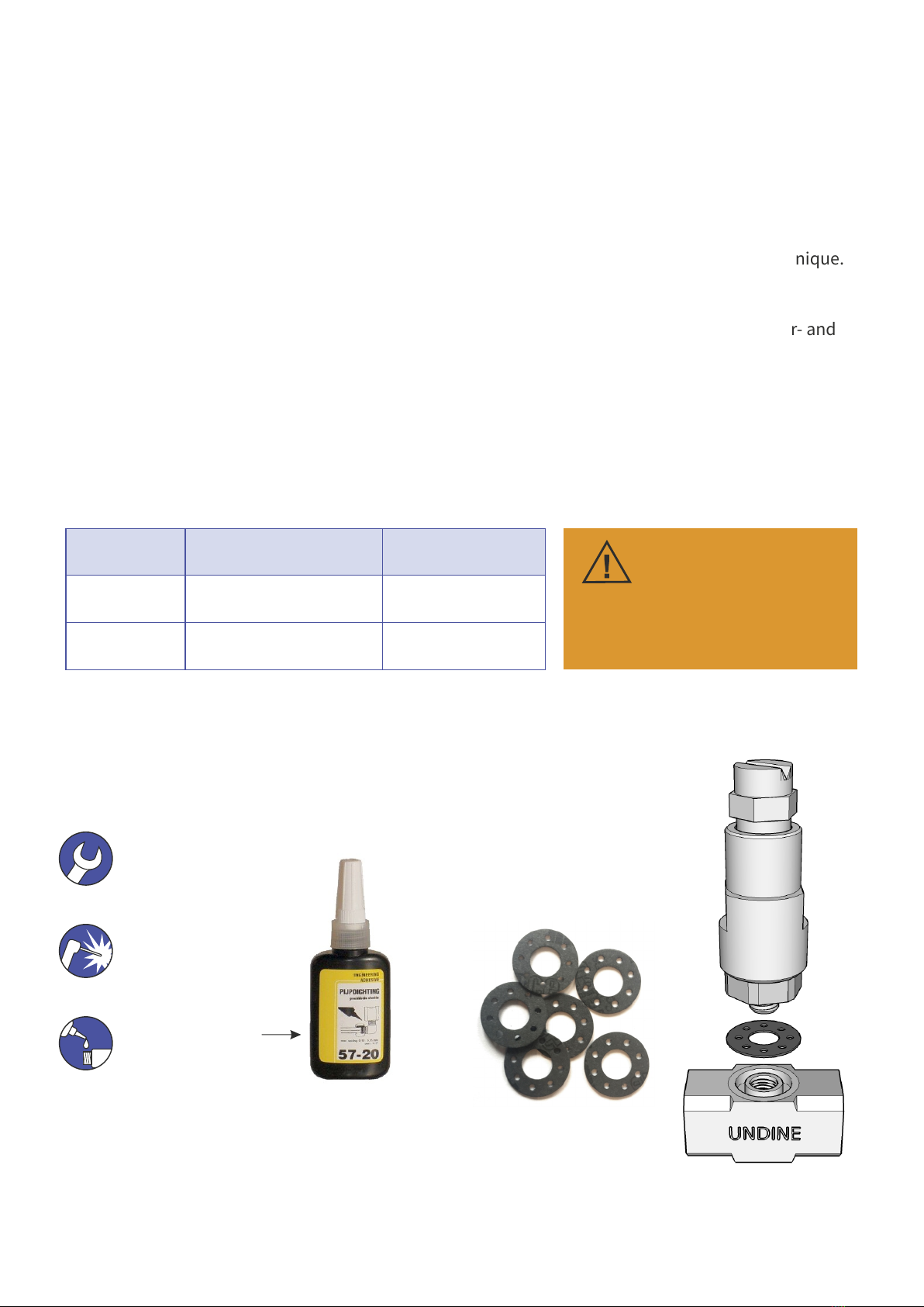
ASSEMBLY GUIDE SYMBOLS
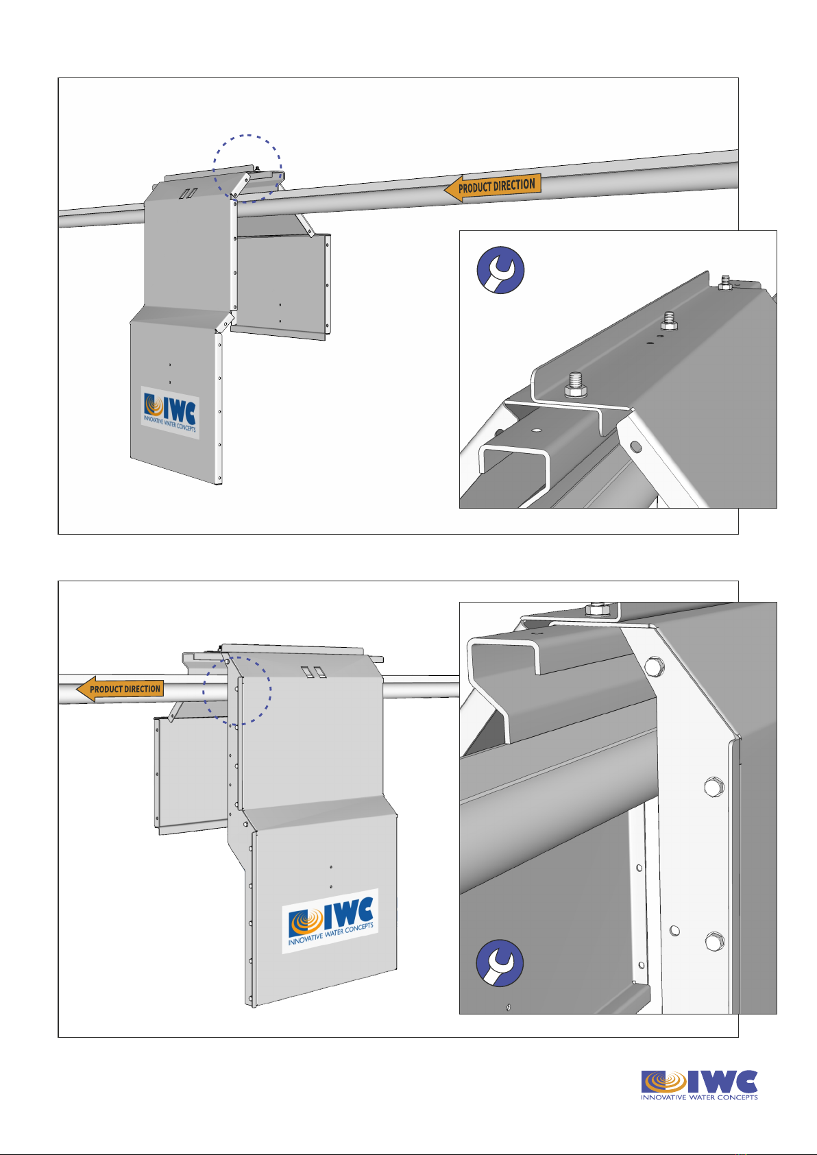
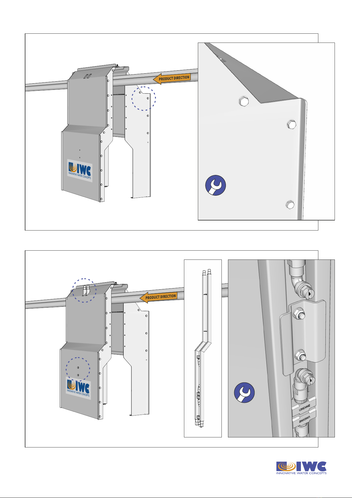
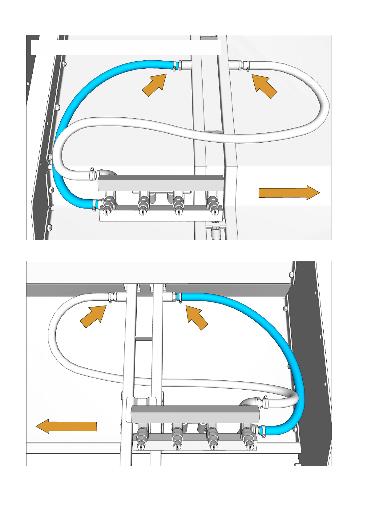
Bolt/screw
Welding
Liquid gasket
(included in package)
Spare gasket rings
for use in the UNDINE®
unit are included.
MAINTENANCE
This is the assembly manual for the:
HD Washing just behind Eviscerator in & outside - super narrow
Article No. HD.BHEV.4x4
The working principle of this equipment is based on the unique UNDINE® water/air mixing technique.
See for details of this technique our introduction movie at www.iwc-international.com
Installation must be performed by qualified technical personnel familiar with poultry slaughter- and
cleaning systems.
Start by checking all parts are available as mentioned in the part list on the next page.
SPECIFICATIONS
Consumption Pressure
Water 1.750 - 2.250 ltrs/hour 10 bar
Air 400 ltrs/min 6 - 8 bar
(actual size)
If the water- and airpressure as
advised are not applied,
the equipment may not function in
accordance with your requirements.
IMPORTANT NOTICE
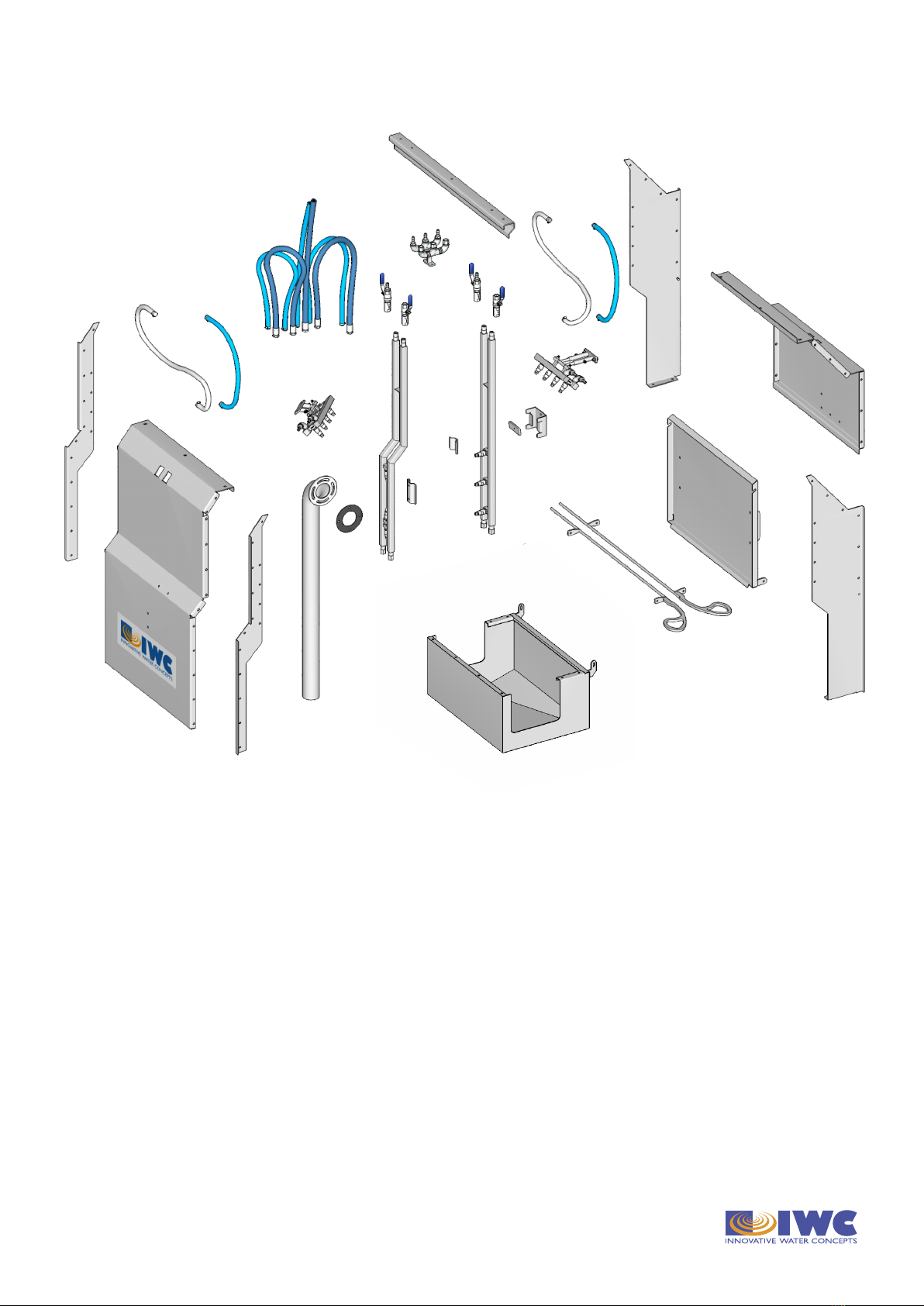
PARTS MOUNTING MATERIAL
1. G-rail
2. Le cabin cover
3. Right cabin cover
4. Back cover LHS
5. Back cover RHS
6. Front cover LHS
7. Front cover RHS
8a. Manifold LHS
8b. Mounting plate
9. Mounting bracket
10a. Manifold RHS
10b. Mounting plate
10c. Mounting plate
11. Upper manifold LHS
12. Upper manifold RHS
13. Inside air/water hoses LHS
14. Inside air/water hoses RHS
15. Air ball/safety valve (2x)
16. Water ball/safety valve (2x)
17. Divider manifold
18. Hose assembly
19. Guide rails (2x)
20. Drip tray
21a. Drain pipe
21b. Drain pipe gasket
22. Door
Bolt M8 x 15 34
Bolt M8 x 20 20
Bolt M8 x 30 7
Safety nut M8 58
Washer M8 119
Bolt M10 x 30 5
Nut M10 3
Safety nut M10 2
Washer M10 5
1
2
6
8a
8b
9
19
20
21a
21b
22
10a
13
14
11
15
15
16
16
12
17
18
10b
10c
7
4
5
3