Step 5 Press “V/A” or “mV/mA” to confirm the set,
it will return to step 4 for reentering if this
voltage value exceed the maximum output
voltage.
SET VOLT=
24.00VNEW= 18
It will exit the setting up voltage operation at any procedure by press ESC
button
For example, how to set up the output voltage at 24.3V
1. To set up by using number keyboard
1. Press the “V-set” button,
2. Enter the password by using the number keypad (if the keypad is unlocked, please do step 4)
3. Press the “Enter” button (if the password is wrong, please do step2 for reentering)
4. Press “2”, “4”, “.” and “3” button to enter the voltage value
5. Press the “V/A” button to confirm the voltage value.
2. To set up by using Rotary knob
1. If the keypad is unlocked by the password, directly rotate the “Rotary knob”, and the voltage will
be continually changed from the previews value according the rotation. At the beginning, the
cursor will be shown on the last number of the value which is indicated on the LCD, you can move
the cursor to the first number, second number etc by using “ ” and “ ” buttons, and then rotate
to change each number, and let it stay at 24.3 V, then confirm the value by pressing “V/A” button.
2. If the keypad is locked by password then press the “V-set” button. Enter the password by using
the number keypad. Press the “Enter” button. Rotate the Rotary knob button to change the value.
Press the “V/A” button to confirm the voltage value.
2.3.2 Set up current
PGPS-36V3A power supply can be set up for a constant current or a maximum current, please see the
following example.
Conditions: voltage=24V, load R=12Ohm, then V/R=2 A, this represents the power supply providing the
load with 2A current. If the current value is set to 2.50A, the power supply works in CV mode, the actual
current value should be displayed on the screen as 2.00A. If the load resistor becomes lower, the current
will increase. When the current exceeds 2.5A, the power supply will change to CC mode, and the output
voltage will drop down to maintain the actual current value to 2.5A.
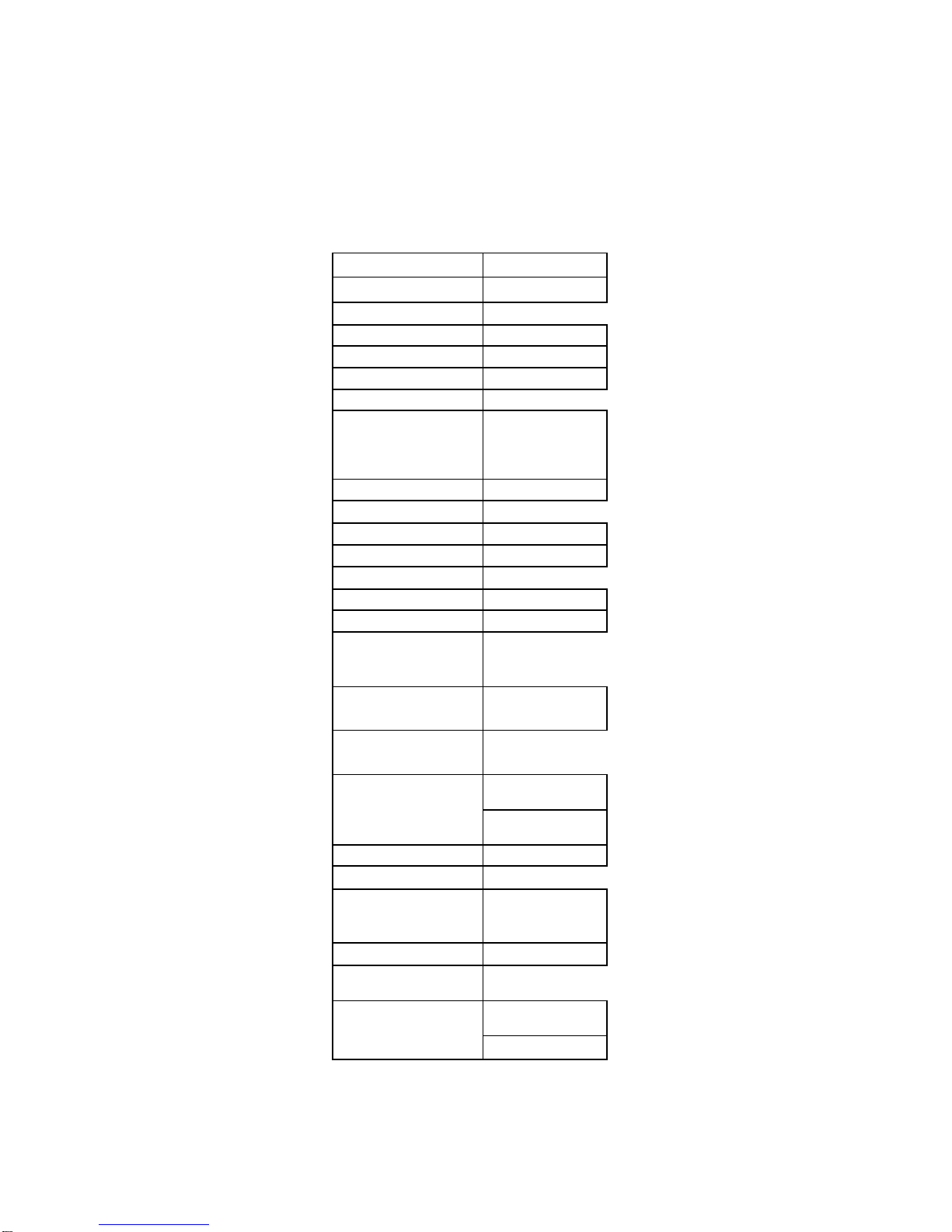
Set up current procedure as follows:
Procedure Operation details LCD display
Step 1 Press “I-set” ENTER
PASSWORD
Step 2 Enter the password ( Or jump to step 4 if
the keypad is unlocked)
ENTER
PASSWORD
Step 3 Press “Enter” button ( it will return to step
2 if your password is wrong for
reentering)
ENTER
PASSWORD****
Step 4 Press “I-set”. Set up a constant current or
a maximum current by using number key
or the rotary knob.
SET
CURR=0mANEW=3
Step 5 Press “V/A” or “mV/mA” to confirm the
set. It will return to step 4 for reentering if
the current value exceeds the maximum
output current.
SET
CURR=0mANEW=
15.0
It will exit the setting up current operation at any procedure by press ESC
button
2.3.3 Enable/disable the output
By default, the power supply is disabled after power on; users can change the output status by using
ON/OFF button.
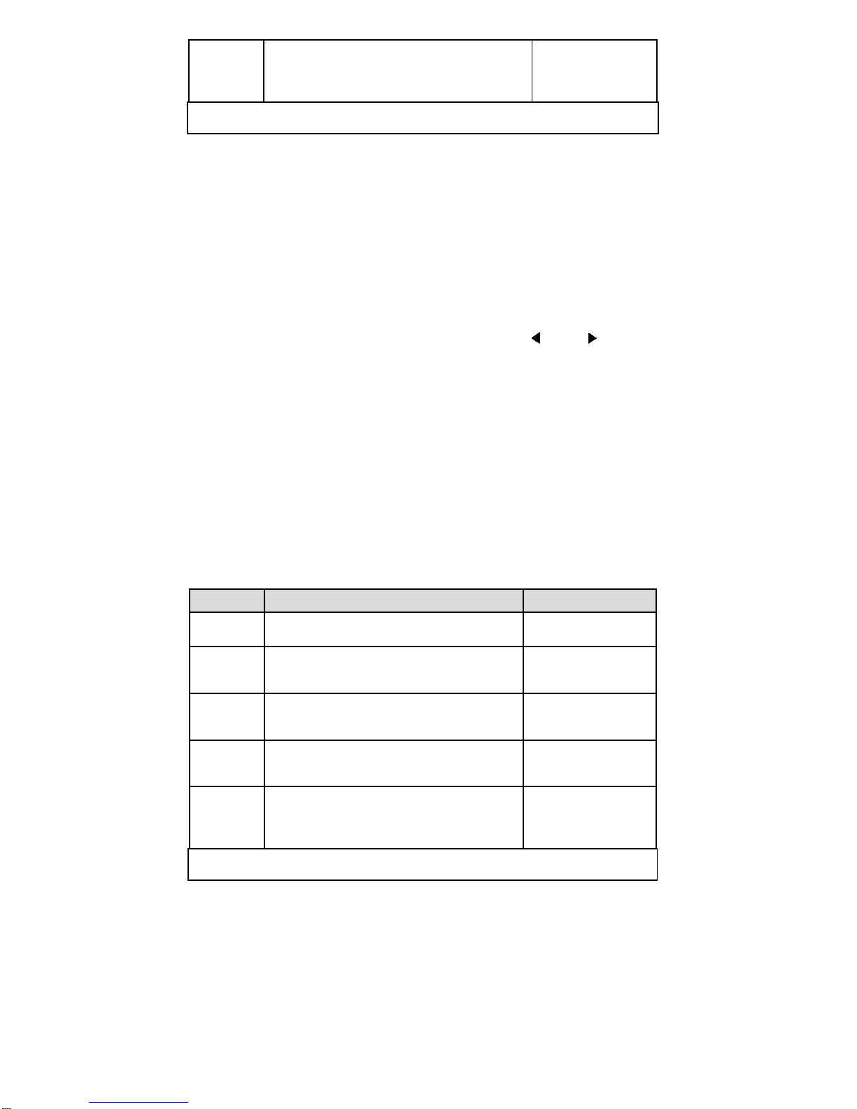
2.3.4 Store parameters
If you often use a voltage and a current of 24V and 2A or 12V and 2.3A, etc., you just need to set up the
data the first time and then store the data in the power supply. When you need it, recall it. The PGPS-
36V3A power supply can store up to 10 sets of parameters.
The parameters include 1) Voltage value; 2) Current value; 3) Maximum voltage; 4) Locked / unlocked
keypad; 5) Maximum power; 6) Baud rate; 7) Communication address.