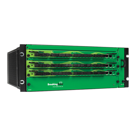
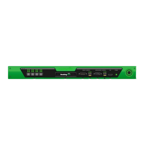
IXIA UHD100T32 User manual

UHD100T32
Release 1.3
Getting Started Guide
913-2626-01
Document version: 202104170944+05:30

Notices
Copyright Notice
© Keysight Technologies 2018–2021
No part of this document may be
reproduced in any form or by any means
(including electronic storage and retrieval
or translation into a foreign language)
without prior agreement and written
consent from Keysight Technologies, Inc.
as governed by United States and
international copyright laws.
Warranty
The material contained in this document is
provided “as is,” and is subject to being
changed, without notice, in future
editions. Further, to the maximum extent
permitted by applicable law, Keysight
disclaims all warranties, either express or
implied, with regard to this manual and
any information contained herein,
including but not limited to the implied
warranties of merchantability and fitness
for a particular purpose. Keysight shall not
be liable for errors or for incidental or
consequential damages in connection with
the furnishing, use, or performance of this
document or of any information contained
herein. Should Keysight and the user have
a separate written agreement with
warranty terms covering the material in
this document that conflict with these
terms, the warranty terms in the separate
agreement shall control.
Technology Licenses
The hardware and/or software described
in this document are furnished under a
license and may be used or copied only in
accordance with the terms of such license.
U.S. Government Rights
The Software is "commercial computer
software," as defined by Federal
Acquisition Regulation ("FAR") 2.101.
Pursuant to FAR 12.212 and 27.405-3 and
Department of Defense FAR Supplement
("DFARS") 227.7202, the U.S. government
acquires commercial computer software
under the same terms by which the
software is customarily provided to the
public. Accordingly, Keysight provides the
Software to U.S. government customers
under its standard commercial license,
which is embodied in its End User License
Agreement (EULA), a copy of which can be
found at
http://www.keysight.com/find/sweula.
The license set forth in the EULA
represents the exclusive authority by
which the U.S. government may use,
modify, distribute, or disclose the
Software. The EULA and the license set
forth therein, does not require or permit,
among other things, that Keysight: (1)
Furnish technical information related to
commercial computer software or
commercial computer software
documentation that is not customarily
provided to the public; or (2) Relinquish
to, or otherwise provide, the government
rights in excess of these rights customarily
provided to the public to use, modify,
reproduce, release, perform, display, or
disclose commercial computer software or
commercial computer software
documentation. No additional
government requirements beyond those
set forth in the EULA shall apply, except to
the extent that those terms, rights, or
licenses are explicitly required from all
providers of commercial computer
software pursuant to the FAR and the
DFARS and are set forth specifically in
writing elsewhere in the EULA. Keysight
shall be under no obligation to update,
revise or otherwise modify the Software.
With respect to any technical data as
defined by FAR 2.101, pursuant to FAR
12.211 and 27.404.2 and DFARS 227.7102,
the U.S. government acquires no greater
than Limited Rights as defined in FAR
27.401 or DFAR 227.7103-5 (c), as
applicable in any technical data. 52.227-14
(June 1987) or DFAR 252.227-7015 (b)(2)
(November 1995), as applicable in any
technical data.
– ii – 913-2626-01

This page intentionally left blank.
913-2626-01 – iii –

Documentation conventions
The following documentation conventions are used in this guide:
Describing interactions with the UI
You can interact with products by using different input methods: keyboard, mouse, touch, and more. So
in most parts of the user documentation, generic verbs have been used that work with any input method.
In cases where input-neutral verbs do not work, mouse-specific verbs are used as the first choice,
followed by touch-specific verbs as the second choice.
See the following table for examples on how you can interpret the different input methods.
Input-neutral Mouse Touch
Select Modify. Click Modify. Tap Modify.
Select Accounts > Other
accounts > Add an account.
Click Accounts > Other
accounts > Add an account.
Tap Accounts > Other
accounts > Add an account.
To open the document in Outline
view, select View > Outline.
To open the document in Outline
view, click View > Outline.
To open the document in
Outline view, tap View >
Outline.
Select Protocols. Click the Protocols tab. Tap Protocols.
-NA- Double-click the Client wizard. Double-tap the Client wizard.
Open the Packages context
menu.
Right-click Packages to open
the shortcut menu.
Long tap Packages to open the
shortcut menu.
Deprecated words
The following words have been replaced with new words, considering the audience profile, our modern
approach to voice and style, and our emphasis to use input-neutral terms that support all input methods.
Old usage... New usage...
shortcut menu, right-click menu context menu
click, right-click select
drag and drop drag
Documentation conventions
913-2626-01 – v –

CONTENTS
Contacting Us iv
Documentation conventions v
Symbols and their meanings x
Product Safety Information xii
Informations sur la sécurité du produit xiii
About This Guide xiv
Record product information xv
Chapter 1 About UHD100T32 1
Overview 1
Specifications 1
Chapter 2 Prerequisites 5
Hardware requirements 5
Software requirements 5
Chapter 3 Getting started workflow 7
Chapter 4 How do I... 9
Unpack UHD100T32 9
Rack mount UHD100T32 10
Connect UHD100T32 14
Sign in to UHD100T32 15
Configure UHD100T32 19
Connect to UHD100T32 24
Restart UHD100T32 25
Shut down UHD100T32 25
– vi – 913-2626-01

Chapter 5 FAQs 27
Appendix A KCOS CLI command reference 31
kcos date-time commands 33
kcos date-time date set 34
kcos date-time date show 35
kcos date-time ntp-servers delete 36
kcos date-time ntp-servers set 37
kcos date-time ntp-servers show 38
kcos date-time ntp disable 39
kcos date-time ntp enable 40
kcos date-time time-zone set 41
kcos date-time time-zone show 42
kcos date-time time set 43
kcos date-time time show 44
kcos deployment commands 45
kcos deployment offline-install 46
kcos deployment packages show 47
kcos deployment progress show 48
kcos exit 49
kcos firewall commands 50
kcos firewall disable 51
kcos firewall enable 52
kcos firewall show 53
kcos networking commands 54
kcos networking dns-servers add 55
kcos networking dns-servers delete 56
kcos networking dns-servers show 57
kcos networking hostname set 58
kcos networking hostname show 59
913-2626-01 – vii –

kcos networking ip set 60
kcos networking ip show 61
kcos shell 62
kcos snapshot commands 63
kcos snapshot create 64
kcos snapshot delete 65
kcos snapshot restore 66
kcos snapshot show 67
kcos system commands 68
kcos system poweroff 69
kcos system reboot 70
kcos system welcome-screen show 71
INDEX 73
– viii – 913-2626-01

This page intentionally left blank.
913-2626-01 – ix –

Symbols and their meanings
The following notational conventions are used in this guide.
Text is bolded to highlight important information.
The caution symbol denotes information that is of critical importance to the operation of
UHD100T32.
The electrical hazard symbol indicates that the power supplies in your system may produce high
voltages and energy hazards, which can cause bodily harm.
The hot surface symbol indicates that a surface or component is hot.
The electrostatic discharge (ESD) symbol indicates proper antistatic precautions should be taken
to avoid damaging electronic equipment including printed circuit boards and components that are
sensitive to static electricity.
The pointer symbol indicates that the information that follows provides helpful tips on how to use
and configure UHD100T32.
Note: Notes are written like this.
– x – 913-2626-01

This page intentionally left blank.
913-2626-01 – xi –

Product Safety Information
Before installing the unit, read all product safety instructions contained in this document.
These instructions contain specific safety messages that will alert you to any hazards
associated with the installation and proper operations of the equipment. Failure to follow
those instructions can result in serious injury or death.
The unit is a 100GE Test System for enhancing network reliability and powered by 2
redundant, load-sharing hot-swappable power supplies, rated 100-240VAC, 50-60Hz, 12-5A
per PS.
Disconnect both power supply cords before servicing.
CAUTION: Risk of Explosion if Battery is replaced by an Incorrect Type. Dispose of Used
Batteries According to the Instructions.
Rack Mount Instructions
1. Elevated Operating Ambient Temperature: If installed in a closed or multi-unit rack
assembly, the operating ambient temperature of the rack environment may be greater
than room ambient temperature. Therefore, consider installing the equipment in an
environment that is compatible with the maximum allowable ambient temperature
specified for the equipment (35° C).
2. Reduced Air Flow: Installation of the equipment in a rack should be such that the
amount of air flow required for safe operation of the equipment is not compromised.
3. Mechanical Loading: Mount the equipment so that it is level in the rack and that a
hazardous condition is not caused.
4. Circuit Overloading: Consideration should be given to the connection of the equipment
to the supply circuit and the effect that overloading of the circuits might have on
overcurrent protection and supply wiring. Appropriate consideration of equipment
nameplate ratings should be used when addressing this concern.
5. Reliable Earthing: Maintain reliable earthing (grounding) of rack-mounted equipment.
Equipment frame should be screwed down to racks to ensure proper grounding path. In
addition, pay special attention to supply connections other than direct connections to
the branch circuit (such as use of power strips).
– xii – 913-2626-01

Informations sur la sécurité du produit
Avant d'installer l'unité, lisez toutes les instructions de sécurité du produit contenues dans ce
document. Ces instructions contiennent des messages de sécurité spécifiques qui vous
alerteront de tout risque associé à l'installation et au bon fonctionnement de l'équipement. Si
ces instructions ne sont pas respectées, cela peut entraîner des blessures graves, voire
mortelles.
L’unité est un système de test 100GE destiné à améliorer la fiabilité du réseau et est
alimentée par 3 blocs alimentations, 100-240 VCA, 50-60 Hz, 12-5 A par PS.
Débranchez les deux cordons d'alimentation avant l'entretien.
CAUTION: Risque d'explosion si la batterie est remplacée par un type incorrect. Jetez les
piles usagées conformément aux instructions.
Instructions de montage en rack
1. Température ambiante de fonctionnement élevée: si installé dans un ensemble en rack
fermé ou multi-unités, la température ambiante de fonctionnement de l'environnement
du rack peut être supérieure à la température ambiante de la pièce. Par conséquent,
envisagez d'installer l'équipement dans un environnement compatible avec la
température ambiante maximale autorisée spécifiée pour l'appareil (35 ° C).
2. Débit d'air réduit: L'installation de l'équipement dans un rack doit être telle que la
quantité d'air requise pour un fonctionnement en toute sécurité de l'équipement ne soit
pas compromise.
3. Chargement mécanique: montez l'appareil de manière à ce qu'il soit de niveau dans le
rack et qu'aucune condition dangereuse ne soit provoquée.
4. Surcharge du circuit: Il convient de prendre en compte le raccordement de
l'équipement au circuit d'alimentation et les effets qu'une surcharge des circuits peut
avoir sur la protection contre les surintensités et le câblage d'alimentation. Lors de la
résolution de ce problème, il convient de prendre en compte les caractéristiques de la
plaque signalétique de l'équipement.
5. Mise à la terre fiable: Maintenez une mise à la terre fiable des équipements montés en
armoire. Le cadre de l'appareil doit être vissé sur les racks pour assurer un bon chemin
de mise à la terre. De plus, faites particulièrement attention aux connexions
d’alimentation autres que les connexions directes au circuit de dérivation (telles que
l’utilisation de barrettes d’alimentation).
Informations sur la sécurité du produit
913-2626-01 – xiii –

About This Guide
The Getting Started Guide provides instructions for the basic set up and configuration of the UHD100T32
fixed chassis.
Notes, Cautions, Warnings
Icons are used throughout the documentation to draw attention to caution and warning statement, and to
highlight information that can help you make more effective use of your system.
Note: Provides information that needs special attention within text.
Provides information that is needed to avoid potential harm to equipment or the environment.
Provides information needed to prevent certain harm to a person, piece of equipment, or the
environment.
UHD100T32 on ixiacom.com
The Ixia UHD100T32 Solution Brief, plus related information, is available from the Ixia website:
https://www.ixiacom.com/products/uhd100t32
Additional information
See the following document for additional information about the UHD100T32 fixed chassis:
lUHD100T32 User Guide
– xiv – 913-2626-01

Record product information
You need to record the product information required during initial system configuration (and for future
reference).
lThe Host Name is the Serial Number, located on a label on the bottom of the unit, and also on the
green pull tab on the right side of the faceplate.
lThe Part Number and Product Key are printed on the label on the back of the unit.
lThe IP address is either assigned by the network's DHCP server or statically assigned by a system
administrator.
Host Name:
Part Number:
IP address:
Record product information
913-2626-01 – xv –

CHAPTER 1 About UHD100T32
This section contains an overview of the UHD100T32 fixed chassis and its specifications.
Section contents:
Overview 1
Specifications 1
Overview
UHD100T32 is the industry’s highest density 100GE test solution that addresses the density challenges of
validating 100GE devices and networks in a cost-effective way. In just a 1U form-factor, the fixed chassis
provides 32 QSFP28 100GE ports, ready for use cases ranging from white box production-line testing to
data center pre-deployment and post-deployment testing.
This fixed chassis supports 100GE, 50GE, 40GE, 25GE, and 10GE fan-out speed test capabilities. It also
includes Keysight’s proven technology for layer 2 to 3 traffic generation and analysis. Optional routing
protocols are available that include OSPF, BGP, and ISIS and RFC 2544 benchmark test capabilities.
Specifications
This section describes the specifications, switch, power, and LED controls of the UHD100T32 fixed
chassis.
Hardware specifications
The current datasheet containing detailed specifications is available on the website:
https://www.ixiacom.com/products/uhd100t32-32-port-100ge-test-system
Front Panel
Front Panel (100G Unit)Layer 2-3 Protocol Support
The UHD100T32 100GE High Density 32-port QSFP28 front panel image is as follows:
– 1 – 913-2626-01

BMC Console
OOB Ethernet
Type-A USB
2x16 QSFP Ports
Status LED
Debug Connector
Channel Status Lamps
A group of four triangular lamps is present between the top and bottom or an odd and even pair of
QSFP ports. These are the port channel status lamps.
Based on the setting that you have chosen by using the port LED selector button, the four lamps indicate
either the state of the MAC channels on the QSFP ports above the lamps, or the states of the MAC
channels on the QSFP ports below the lamps.
The following image shows the port channel status lamps:
LED Selector Button and Bank Indicator Lamps
The port LED Selector button is located at the lower right of the front panel, and is labeled LED Select.
There are two bank indicator lamps labeled TOP and BOT to the right of the button. These lamps indicate
whether all the port lamps are showing the port state for TOP or BOT.
You can press the LED Selector button to toggle between the two states.
Chapter 1 About UHD100T32
913-2626-01 – 2 –

The following image show the LED Selector button and the bank indicator lamps:
The following is an example of how the bank indicator lamps work:
See the leftmost top and bottom pair of QSFP ports on the front panel and assume a configuration of 4 ×
25G on each QSFP port (four MAC channels of 25G each). If you select the TOP bank, the four lamps show
the state of the top QSFP port's four channels from left to right as follows:
lQSFP Port 1/MAC Channel 1
lQSFP Port 1/MAC Channel 2
lQSFP Port 1/MAC Channel 3
lQSFP Port 1/MAC Channel 4
Port Status LED
The LED port channel status lamp indicates the following:
Color Port Status
Green Port/Channel is active (link is up)
Blue Port/Channel is enabled but the link is not up
Orange Port/Channel is disabled by an administrator
LED Off Port/Channel is not enabled or has not been added
Rear Panel
The UHD100T32 100GE High Density 32-port QSFP28 rear panel image is as follows:
Chapter 1 About UHD100T32
– 3 – 913-2626-01

RS485 1 (Do not use)
RS485 3 (Do not use)
RS485 2 (Do not use)
GPI0 1 (Do not use)
Chapter 1 About UHD100T32
913-2626-01 – 4 –

CHAPTER 2 Prerequisites
This section contains the prerequisites to configure and to get started with the UHD100T32 fixed chassis.
Section contents:
Hardware requirements 5
Software requirements 5
Hardware requirements
You need a management workstation (such as a laptop) for a serial connection or a monitor and keyboard
to perform the initial system configuration.
For a serial connection, the workstation requires the following:
lA 9-pin serial port or a USB-to-Serial converter
lAn RJ-45 100 M/1G/10G Ethernet port
lTerminal emulation software that supports SSH and serial connections (we recommend you to use
PuTTY as an open source option). Configure the terminal software as follows:
nUse UTF-8 character set with VT100 terminal (HyperTerminal, PuTTY, TeraTerm, or
equivalent)
nSelect the corresponding COM port number for your serial port (for example, COM1)
nSpeed: 9600
nData bits: 8
nStop bits: 1
nParity: None
nFlow Control: None
Software requirements
The UHD web application uses the UHD100T32 fixed chassis traffic ports. This section outlines the
supported versions of these applications.
Support for UHD100T32 is provided in the following applications for the indicated software versions:
Application Version
– 5 – 913-2626-01
Table of contents
Other IXIA Network Hardware manuals
Popular Network Hardware manuals by other brands

Grandstream Networks
Grandstream Networks UCM Series Security Manual

Atlantis Land
Atlantis Land DiskMaster NASG302D user manual

Paradyne
Paradyne Hotwire 5620 installation instructions

Idis
Idis DR-1204P Operation manual

Overtech
Overtech Ov-W650 user guide

Clearfield
Clearfield WaveSmart Circulator installation manual