Fig. 22
Power
cable
Fig. 16
Template Guide
Part number 611028_A
Approved by the appropriate
electrical supply authorities.
I N H O M E
WARR ANTY
questions or warranty matters:
Sampford IXL Pty Ltd
Service Department
Phone: 1300 727 421
Fax:
1300 727 425
aftersalesser
www.ixlappliances.com.au
Fig. 13: Use template to mark position of module
Installation
The Neo modules may be installed between joists
using the spring clips, clearances must be maintained
as per Fig. 2b, 2c & 2d.
IMPORTANT:
cut or notched to install the appliance.
Joists, beams and rafters shall not be
Depending on your model, the modules have a weight
of 1.0 – 2.6 kg (see below). If adequate support is not
available for the modules, it may be necessary to
provide extra strengthening.
If ceiling battens have been cut to install this
then ensure that the cut ceiling battens are
adequately secured to rafters.
product
NOTE: This product must be installed by a qualified
installer. Ensure power is off to location of Tastic.
Cut out hole for Neo module
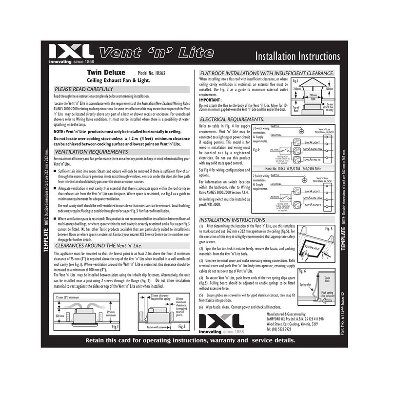
After determining the location of the Neo module,
mark out and cut aperture in ceiling using the
appropriate template. Trim the template to the outside
of the black outline.
Vent and Vent n Lite modules (models
34101, 34102, 35101 & 35102)
1.
mm dia. ducting. Determine the length of ducting
required ensuring that the length is as short as
possible. Refer to Fig’s 19-21 to attain optimum
performance.
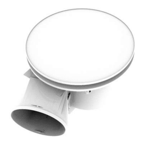
2. Tape a length of ducting 1 m long (max) to the
blower inlet. Tape remaining length of ducting to
exit of blower.
3. Feed ducting and blower through hole in ceiling.
While feeding ducting into ceiling direct it towards
the installation position of the outlet grille. Position
blower so that the short length of ducting and
stripped wire (models 34101 & 34102) is sitting
next to the hole as per Fig. 22.
4. Make the necessary electrical connections. Refit
terminal cover.
5. Tape short length of ducting, from blower inlet, to
transition.
6. Push unit into ceiling aperture, allowing metal
springs to snap open. As the unit is raised into the
ceiling, ensure electric cable do not rest on the
unit.
7. To secure the unit in position, push lower ends of
springs apart (Fig 16.). Ceiling board thickness
should be adjusted to enable springs to be fitted
without excessive force.
8. Bring fascia up to unit and connect the earthing
wire (models 34101 & 34102). Clip fascia into the
unit. Fig 17.
9. Remove downlight mounts and fit down lights.
Connect lamp holders to downights and refit
downlight mounts (models 34101 & 34102).
10. Turn on the power at the isolating switch and
check operation of the unit.
These products have been designed to suit 150
Fig. 19: Straight ducting
Performance
Fig. 20: Gradual bends,
ducting stretched straight.
100%
Performance
Neo Light small – approx 1.0 kg
Neo Light large – approx 1.3 kg
Neo Vent n Lite - approx 1.9 kg
Neo Vent - approx 1.5 kg
Neo Heat - approx 2.6 kg
Installation Installation
Fig. 23
Fig. 21: Tightly compressed bends
Performance
100%
Fig. 17
Modules - Heat • Vent • Light
Model: 33132 Neo Light Small Silver - Hardwired
Model: 33141 Neo Light Large White - Hardwired
Model: 33142 Neo Light Large Silver - Hardwired
Model: 34101 Neo Vent n Lite White - Hardwired
Model: 34102 Neo Vent n Lite Silver - Hardwired
Model: 33131 Neo Light Small White - Hardwired
Electrical Rating: 230~240 V. 50 Hz.
Model: 35101 Neo Vent White - Hardwired
Model: 35102 Neo Vent Silver - Hardwired
Model: 36111 Neo Heat White - Hardwired
Model: 36112 Neo Heat Silver - Hardwired
Heat module (models 36111 & 36112)
IMPORTANT: Under no circumstances shall this
appliance be covered with insulating material or
similar material.
1. Unscrew terminal cover and make necessary
electrical connections. Refit terminal cover. Do
not turn on power to unit.
2. Push unit into ceiling aperture, allowing metal
springs to snap open. As the unit is raised into the
ceiling, ensure electric cable does not rest on the
unit.
3. To secure the unit in position, push lower ends of
springs apart (Fig 16.). Ceiling board thickness
should be adjusted to enable springs to be fitted
without excessive force.
4. Bring fascia up to unit and connect the earthing
wire. Clip fascia into the unit. Fig 17.
5. Using care, fit the tubular heat lamps into the
lamp holders. Be careful not to touch the glass
surface as oils from skin can shorten the life of
the glass lamp. A clean soft cloth or tissue is
recommended. Ensure that the white reflective
layer on the tubular heat lamp is on the upper side
of the lamp, ie lamp is pointing downwards.
6. Fit the glass sheets to the heat lamp reflector
bodies Fig. 18.
7. Turn on the power at the isolating switch and
check operation of the unit.
Installing the Grille
1.
wall. Feed ducting out through this hole and tape
to the Grille baseplate.
2. Feed the ducting back through the hole so that the
Grille base is against the eaves or outer wall.
3. Fix Grille base with four 6 G screws and snap ft
the Grille louvres over the Grille base as shown in
Fig. 23.
Note: A piece of fly screen can be fitted to the Grille
base prior to fitting the Grille louvre.
Cut a hole 160 mm in diameter in eaves or outer
13
2
Fig. 18
TEMPLATE MODELS: 36111 & 36112 TEMPLATE MODELS: 34101, 34102, 35101 & 35102
Cut-out size: 292mm x 332mm Cut-out size: 214mm x 332mm
Model: 33131, 33132, Neo Light Small Model: 33141, 33142, Neo Light Large
Model: 36111, 36112, Neo Heat Model: 34101, 34102, Neo Vent n Lite Model: 35101, 35102, Neo Vent
T
rim to outside of black line.
T
rim to outside of black line.
IXL Pty Ltd
Service Department
Free Call: 1300 727 421
www.ixlappliances.com.au
Model: 34101 Neo Vent n Lite White - Hardwired
Model: 34102 Neo Vent n Lite Silver - Hardwired
Model: 35101 Neo Vent White - Hardwired
Model: 35102 Neo Vent Silver - Hardwired
Model: 36111 Neo Heat White - Hardwired
Model: 36112 Neo Heat Silver - Hardwired
Electrical Rating 230 ˜ 240 V. 50 Hz


