manuals.online logo
Brands
  1. Home
  2. •
  3. Brands
  4. •
  5. IXL
  6. •
  7. Ventilation Hood
  8. •
  9. IXL tastic LUMINATE 34401 User manual

IXL tastic LUMINATE 34401 User manual

C
D
F
E
All appliances must be mounted so that the lowest
point is at least 2.2m above the floor. The Vent
body and ducted blower is designed to fit a ceiling
cavity or between – floor space with a minimum
height of 245 mm. The modules may be installed
between joists using the spring clips (Fig. 2c).
Ensure that the outlet of the Vent unit is directed
towards the outer wall. If the desired orientation of
the Vent unit directs the ducting across ceiling joists
ensure that the closest ceiling joist is not within
150 mm of the Vent outlet.
Figure 2a - Minimum Blower Clearances
Figure 2b - Minimum Unit Clearances
Figure 2c
C: Models: 34401, 34402, 35401 & 35402-50 mm
Models: 36411 & 36412 - 75 mm
D: Models: 34401, 34402, 35401 & 35402-195 mm
Models: 36111 & 36112 - 151 mm
E: Models: 34401, 34402, 35401 & 35402-35 mm
to structural member
Models: 36411 & 36412 - 50mm to
structural members.
F: Models: 34401, 34402, 35401 & 35402-150 mm.
Models: 34401, 34402, 35401 & 35402-35 mm
min.clearance is required near all joists
Models: 36411 & 36412-50 mm min.
clearance is required near all joists.
Fig. 2b: Minimum clearances for installation
Fig. 2c: Minimum clearances for installation
Overview
Electrical Requirements
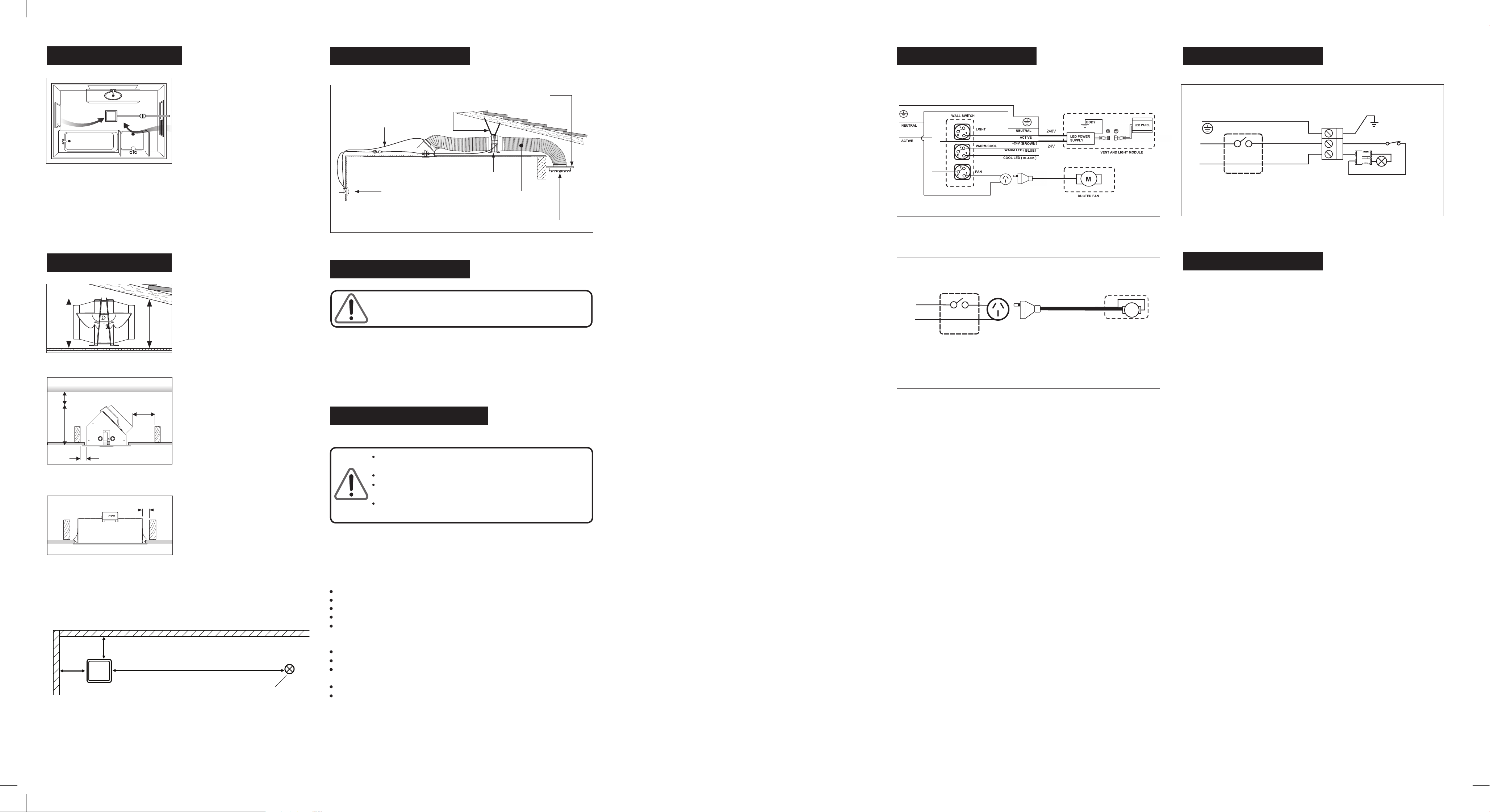
Fig. 6: Wiring diagram for models 34401 and 34402, Luminate Vent & Light
Modules may be connected to a lighting or power circuit if loading permits. These models are for
wired-in installation and wiring must be carried out by a registered electrician. Switches and a
wall plate are not provided with the Vent & Heat Luminate modules. Do not use these products
with any solid state speed control or commercial dimming device.
Luminate Vent & Light module is fitted with a custom LED panel.
For Luminate modules fitted with LED centre lamps. To ensure
correct operation and to prolong the life of the LEDs please wire as
per the following wiring diagrams for the appropriate model.
Wiring Diagr ams
Fig. 8: Wiring diagram for model 36411 and 36412, Luminate Heat.
Wiring – Aust & NZ
For the heat module (models 36411, 36412) a local isolating switch (not supplied) must be
incorporated in the fixed wiring to the appliance to allow disconnection of supply during
maintenance. A local isolating switch (not supplied) must be incorporated in the fixed wiring
to the appliance to allow disconnection of supply during maintenance.
The Tastic Luminate is classified as a Room Heater and as such:
In accordance to AS/NZS 3000 this isolating switch shall be -
(a) installed immediately adjacent to an entrance to, or within, the room where the room heater
is located; or
(b) installed on the switchboard at which the room heater final subcircuit originates.
Refer to AS/NZS 3000 for further regulations regarding isolating devices.
It must not be installed where it can be reached from the bath or shower recess or enclosure
(see AS/NZS 3000 Section 7).
Vent & Vent & Light models 34401, 34402, 35401 & 35402:
Switch the power outlet for the Inline Blower with a wall switch (not supplied with Vent Module)
as per the Wiring Diagrams. Do not mount the power outlet for the Inline Blower more than 200 mm
from the Inline Blower.
Fig. 7: Wiring diagram for model 35401 and 35402, Luminate Vent
E
35401 & 35402: 0.3A 50Hz
M
DUCTED FAN
ACTIVE
NEUTRAL
36411 & 36412: 3.3A 50Hz
BODY
ACTIVE
NEUTRAL
TERMINAL BLOCK
THERMAL SWITCH 65°C
HEAT L AMP
Wiring Diagr ams
Fig. 4: Layout of Luminate Vent & Light
Neo Models: 34401, 34402, 35401, 35402
Wall switch (not supplied)
Inline Ducted Blower
Ducting
Air outlet grille
positioned in eaves lining
Exterior
of home
Eaves
lining
Vent unit
Flexible support
Vent & Light Cable Wall Switch (not supplied)
Wall Switch (not supplied)
Recommended Ceiling Heights
Minimum ceiling height for all models Tastic
Luminate is 2.2m.
Ensure that the exhaust outlet of the Tastic is
directed towards the outer wall.
For maximum efficiency and fan performance
there are a few key points to
keep in mind when installing your Tastic.
Sufficient air inlet into room
Steam will only be removed if there is sufficient
flow of air through the room.
Ensure generous inlets exist through windows,
vents or under the door.
Airflow path from inlet to fan should ideally
pass over the steam sources (see Fig.1)
Bathrooms which have high ceilings, are larger
then average, or have an open
shower may all require an additional ventilation
fan to be installed.
We recommend that you visit our website for
further details and suggestions on
effectively ventilating your bathroom.
Clearances
Ventilation Requirements
Fig. 2a: Minimum blower clearances
215
mm
Blower
Height
min.
overall
height
230mm
15mm clearance above unit
Fig.1: Ideal placement of Tastic.
Min
300mm Min
1500mm
Wall
Wall
Min
300mm
Sprinkler System / Smoke Detector
Fig 3. Clearance to walls
Luminate Heat Module Clearances
Safety
Safety Features
Thermal Switch (Heat Module only)
When for any reason the temperature inside the unit reaches 65°C, the thermal switch will cut off
power to the Tastic Luminate. When the temperature drops, the thermal switch will automatically reset
and reconnect the power.
Do not look directly into heat lamps when in use.
Tastic products are not tanning lamps.
Make sure the lamps have cooled and power is off to the Tastic before removing lamps for replacement.
Do not operate this appliance without the fascia or glass panels in position.
This appliance is not intended for use by persons (including children) with reduced physical, sensory or
mental capabilities, or lack of experience and knowledge, unless they have been given supervision or
instruction concerning use of the appliance by a person responsible for their safety.
Young children should be supervised to ensure they do not play with the appliance.
This appliance must be mounted with the lowest point at least 2.2 metres from the floor.
If the supply cord is damaged, it should be replaced by the IXL Home or its service agent or a
similarly qualifed person in order to avoid a hazard.
This appliance must not be mounted immediately below a socket outlet.
Regulations concerning the discharge of air have to be fulfilled.
WARNING: Curtains or combustible material may ignite if in contact or close proximity with the heater.
NOTE: This product must be installed by a qualified installer.
Locate the Tastic in accordance with the requirements of the current Australian/New Zealand Wiring
Rules AS/NZS 3000 relating to damp situations.
In some installations this may mean that no part of these Tastic may be located directly above any part
of a bath or shower recess or enclosure. For unenclosed showers refer to Wiring Rules conditions.
Switches and other controls must not be located where they can be touched by a person in the bath
or shower.
Read through these instructions completely before commencing installation.
When installed, the Tastic Luminate appliance shall, under no
circumstance, be covered with insulating material or similiar material.
This Tastic unit must be installed horizontally in the ceiling.
There is no IP rating on the Luminate Heat module. Vent and Vent
& Light modules have IPX4 rating.
To prevent overheating do not place any object within 1 metre
of heat lamps.
Luminate Vent Area Suitability:
8.3m2with shower / 20.8m2without shower
Based on standard 2.4m ceiling height
Luminate Vent & Light Area Suitability:
8.3m2with shower / 20.8m2without shower
Exhaust Fan Capacity 400m3/hr
Recommended Room Size
Fig. 19
Power
cable
Fig. 12
Part number 611054_A
Fig. 11: Use template to mark position of module
Installation Installation Installation
The Luminate modules may be installed between joists
using the spring clips, clearances must be maintained
as per Fig. 2b, 2c & 2d.
IMPORTANT:
cut or notched to install the appliance.
Joists, beams and rafters shall not be
Depending on your model, the modules have a weight
of 1.5 – 2.8 kg (see below). If adequate support is not
available for the modules, it may be necessary to
provide extra strengthening.
If ceiling battens have been cut to install this
then ensure that the cut ceiling battens are
adequately secured to rafters.
product
NOTE: This product must be installed by a qualified
installer. Ensure power is off to location of Tastic.
Cut out hole for Luminate module
After determining the location of the Luminate module,
mark out and cut aperture in ceiling using the
appropriate template. Trim the template to the outside
of the black outline.
Vent and Vent & Light modules (models
34401, 34402, 35401 & 35402)
1.
2. Cut and tape a length of ducting 1 m long (maximum)
to the blower inlet. If the exhaust air is to exit outside,
tape remaining length of ducting to exit of blower.
3. Feed ducting and blower through hole in ceiling directing
it towards the installation position of the outlet grille.
Position blower so that the short length of ducting and
power supply cable (models 34401 & 34402) is sitting
next to the hole as per Fig. 19.
4. Make the necessary electrical connections per
wiring diagrams. on the reverse of this sheet
Note the wall switch (included) wiring for the warm/
cool LED in the vent & Light module (34401/34402)
5. Tape short length of ducting, from blower inlet, to
transition.
6. Push unit into ceiling aperture, allowing metal
springs to snap open. As the unit is raised into the
ceiling, ensure electric cable do not rest on the
unit.
7. To secure the unit in position, push lower ends of
springs apart (Fig 12.). Ceiling board thickness
should be adjusted to enable springs to be fitted
without excessive force.
8. Clip fascia into the unit. Fig 13.
9. Turn on the power at the isolating switch and
check operation of the unit.
These products have been designed to suit 150
mm dia. ducting. Determine the length of ducting
required ensuring that the length is as short as
possible. Refer to Fig’s 16-18 to attain optimum
performance.
Fig. 16: Straight ducting
Performance
Fig. 17: Gradual bends,
ducting stretched straight.
100%
100%
Performance
Luminate Vent & Light - approx 2.8kg
Luminate Vent - approx 1.5 kg
Luminate Heat - approx 2.6 kg
Fig. 20
Fig. 18: Tightly compressed bends
Performance
100%
Fig. 13
Heat module (models 36411
& 36412)
IMPORTANT: Under no circumstances shall this
appliance be covered with insulating material or
similar material.
1. Unscrew terminal cover and make necessary
electrical connections. Refit terminal cover. Do
not turn on power to unit.
2. Push unit into ceiling aperture, allowing metal
springs to snap open. As the unit is raised into the
ceiling, ensure electric cable does not rest on the
unit.
3.
4.
To secure the unit in position, push lower ends of
springs apart (Fig 12.). Ceiling board thickness
should be adjusted to enable springs to be fitted
without excessive force.
Clip fascia into the unit. Fig 13.
Installing the Grille
1.
wall. Feed ducting out through this hole, cut to
the minimum duct length, and tape to the
Grille baseplate.
2. Feed the ducting back through the hole so that the
Grille base is against the eaves or outer wall.
3. Fix Grille base with four 6 G screws and snap ft the
Grille louvres over the Grille base as shown in
Fig. 20.
Note: A piece of fly screen can be fitted to the Grille
base prior to fitting the Grille louvre.
Cut a hole 160 mm in diameter in eaves or outer
TEMPLATE MODELS: 36401, 36402 TEMPLATE MODELS: 34401, 34402, 35401 & 35402
Cut-out size: 292mm x 332mm Cut-out size: 214mm x 332mm
Fitting Heat Lamps
NOTE: Natural skin oils and salts damage new halogen
lamps and shorten their life. Only handle a new heat
lamp with soft, dry, clean, lint-free cloth or paper.
You can wear gloves, cover your fingers or wrap the
heat lamp until it is installed (so long as you remove
all cloth or paper when finished). If your skin touches
a new heat lamp, wipe it gently with alcohol-moistened
cloth or paper.
The heat lamp is half coated with a white reflector.
When you grasp the heat lamp, face the back of the
reflector to the ceiling (so you can see the heat
lamp’s filament). Not doing this will reduce
performance. (Fig 14)
5. Ensure power is off at the isolating switch
6. Fit one end of the heat lamp into a socket and
gently push it away from the other socket. (Fig 14)
7. When there is enough room, fit the other end of
the heat lamp into its socket.
8. Gently rotate the heat lamp to ensure it is correctly
seated (i.e. it looks like the old one did before
you removed it).
9. Fit the glass sheets to the heat lamp reflector
bodies Fig. 15.
10.Turn on the power at the isolating switch and
check operation of the Tastic.
Fig.14
Fig. 15
13
2
Filament
Socket
Heat Lamp
Reflector
Installation Guide
Model: 34401 Luminate Vent & Light
White Module
Model: 34402 Luminate Vent & Light
Silver Module
Model: 36411 Luminate Heat
White Module
Model: 36412 Luminate Heat
Silver Module
Model: 35401 Luminate Vent
White Module
Model: 35402 Luminate Vent
Silver Module
Electrical rating: 230~240 V. 50 Hz.
VENT & LIGHT VENT MODULE
HEAT MODULE
LUMINATE®
Approved by the appropriate
electrical supply authorities.
For comments, questions or warranty matters:
IXL Home Pty Ltd
Australia
Free Call: 1300 727 421
Fax: 1300 727 425
[email protected]
www.ixlappliances.com.au
© Copyright IXL Home, 2018
New Zealand
Free Call: 0800 727 421
[email protected]
www.ixlappliances.co.nz

This manual suits for next models

5

Other IXL Ventilation Hood manuals

IXL 10330 Ventflo Mounting instructions

IXL

IXL 10330 Ventflo Mounting instructions

IXL 10380 User manual

IXL

IXL 10380 User manual

IXL Tastic 31211 Neo Single User manual

IXL

IXL Tastic 31211 Neo Single User manual

Popular Ventilation Hood manuals by other brands

Beko CCB 5140 XA user manual

Beko

Beko CCB 5140 XA user manual

Zanussi Professional Export 642382 Specifications

Zanussi

Zanussi Professional Export 642382 Specifications

Amica OSC6212 Series operating instructions

Amica

Amica OSC6212 Series operating instructions

Windster WALL MOUNT Series user manual

Windster

Windster WALL MOUNT Series user manual

AIRLUX AHMI971BK manual

AIRLUX

AIRLUX AHMI971BK manual

Faber INCA HC SS installation instructions

Faber

Faber INCA HC SS installation instructions

Franke 400 User instructions

Franke

Franke 400 User instructions

Klarstein 10011462 Information booklet

Klarstein

Klarstein 10011462 Information booklet

Award PPS902SI instruction manual

Award

Award PPS902SI instruction manual

Bosch DHD3614UC installation instructions

Bosch

Bosch DHD3614UC installation instructions

Whirlpool AKR902TBIX Instructions for use

Whirlpool

Whirlpool AKR902TBIX Instructions for use

Logik LCH655SSE Instruction book

Logik

Logik LCH655SSE Instruction book

Smeg KSEV97X-2 instruction manual

Smeg

Smeg KSEV97X-2 instruction manual

Hoover HDSV985W Installation and user manual

Hoover

Hoover HDSV985W Installation and user manual

Electrolux EFV536K user manual

Electrolux

Electrolux EFV536K user manual

montpellier CHG613MB-EDGE Installation and operating instructions

montpellier

montpellier CHG613MB-EDGE Installation and operating instructions

Miele DAS 4630 Operating and installation instructions

Miele

Miele DAS 4630 Operating and installation instructions

Hotpoint HE61 Instructions for installation and use

Hotpoint

Hotpoint HE61 Instructions for installation and use

manuals.online logo
manuals.online logoBrands
  • About & Mission
  • Contact us
  • Privacy Policy
  • Terms and Conditions

Copyright 2025 Manuals.Online. All Rights Reserved.