J-Alert JA-2030 User manual

Operators Manual
Model JA-2030
April 2012 Ver 1.4


___________________________________________________________
This document contains designs and other information which are the property of Dyplex
Communications Limited. Except for rights expressly granted by contract, this document may not,
in whole or in part, be duplicated, disclosed or used without the prior written permission of Dyplex
Communications Limited. pg. 1
INDEX
Overview ……..………………………………………………. 2
Theory of operation ...…………………………………… 3
Front Panel controls …………………………………….. 5
Rear Panel connections ………………………………… 7
Installation and Operation ..…………………………. 8
Support & Service ………………………………………… 17
Warranty ………………………………………………………. 18
Examples of Jamming Devices ……………………. 20

___________________________________________________________
This document contains designs and other information which are the property of Dyplex
Communications Limited. Except for rights expressly granted by contract, this document may not,
in whole or in part, be duplicated, disclosed or used without the prior written permission of Dyplex
Communications Limited. pg. 2
Jammer Detector
Models JA-2030
OVERVIEW
The J-Alert is multi-band receiver capable of detecting
Radio Frequency Jamming. The J-Alert uses signal
analysis to identify valid communications and
differentiate them from malicious Radio Frequency
Jamming signals.
When Jamming is detected, visual alerting of the
jammed radio spectrum is identified on the front of the
unit and the RSSI (received signal strength indication)
LED’s on the front display are activated as well as an
audible beep will also be heard. The LED activity will
indicate target vehicle position relative to the J-Alert
equipped vehicle.

___________________________________________________________
This document contains designs and other information which are the property of Dyplex
Communications Limited. Except for rights expressly granted by contract, this document may not,
in whole or in part, be duplicated, disclosed or used without the prior written permission of Dyplex
Communications Limited. pg. 3
Theory of Operation
The J-Alert contains a number of sensitive radio frequency
receivers tuned to specific radio bands.
Model JA-2030 (Europe & Brazil)
GPS – L1
GSM /900 – GSM/1800 MHz
UMTS
These radio receivers are tuned to the Downlink (Site)
frequencies of their respective cellular bands. Very fast scanning
within the bands is used with an adaptive signal analysis to
identify jamming signals from legitimate radio signals. When
jamming is detected the receiver identifying the jammed signal
will indicate band jamming on the front panel illuminating the
respective led’s.

___________________________________________________________
This document contains designs and other information which are the property of Dyplex
Communications Limited. Except for rights expressly granted by contract, this document may not,
in whole or in part, be duplicated, disclosed or used without the prior written permission of Dyplex
Communications Limited. pg. 4
(BAND JAMMING LED INDICATORS)
Cell Jamming
When cellular jamming is detected on any of the cellular bands,
the Cell LED will illuminate. RSSI LED indication will be displayed
indicating the strength of the Cellular Jammer received signal.
GPS Jamming
When jamming of the GPS L-1 frequency is detected, the GPS
LED will illuminate and tracking using the RSSI LED display is
active.

___________________________________________________________
This document contains designs and other information which are the property of Dyplex
Communications Limited. Except for rights expressly granted by contract, this document may not,
in whole or in part, be duplicated, disclosed or used without the prior written permission of Dyplex
Communications Limited. pg. 5
Front Panel
(RSSI LED’S)
Front Panel Controls
Ext/Off/Bat : 3 position power switch
Ext – power is provided via usb plug on the back of the
unit 5vdc direct or a 12v to 5v Cigarette lighter/convertor
plug
Off – Unit is turned off.
Bat – Internal 5v Li-polymer rechargeable battery is used.
JA-2030 will operate for approximately 2 hours.
Charging of the internal battery occurs when the external
power is connected.
PWR: Red LED illuminates when J-Alert is turned on and power
is supplied.

___________________________________________________________
This document contains designs and other information which are the property of Dyplex
Communications Limited. Except for rights expressly granted by contract, this document may not,
in whole or in part, be duplicated, disclosed or used without the prior written permission of Dyplex
Communications Limited. pg. 6
Cell: Yellow led illuminates when Jamming is indicated
on at least one of the Cellular frequency Bands.
GPS: Yellow led illuminates when Jamming is indicated
on the GPS L1 frequency.
Signal Strength/RSSI
6 LED display that will indicate the RSSI of the GPS
L1 or Cellular frequency that is being jammed.
Used for tracking the jammer.

___________________________________________________________
This document contains designs and other information which are the property of Dyplex
Communications Limited. Except for rights expressly granted by contract, this document may not,
in whole or in part, be duplicated, disclosed or used without the prior written permission of Dyplex
Communications Limited. pg. 7
Rear Panel
Rear Panel Connections
Relay Out 2.5mm Stereo jack providing a 3 wire N/O N/C dry
contacts for remote triggering of external devices.
On valid alarm sense the relay will activate and
latch for 10 sec.
Antennas SMA whip antenna
USB Supply USB connection for external power input 5v dc.
JA-2030

___________________________________________________________
This document contains designs and other information which are the property of Dyplex
Communications Limited. Except for rights expressly granted by contract, this document may not,
in whole or in part, be duplicated, disclosed or used without the prior written permission of Dyplex
Communications Limited. pg. 8
Installation and Operation
Package Contains
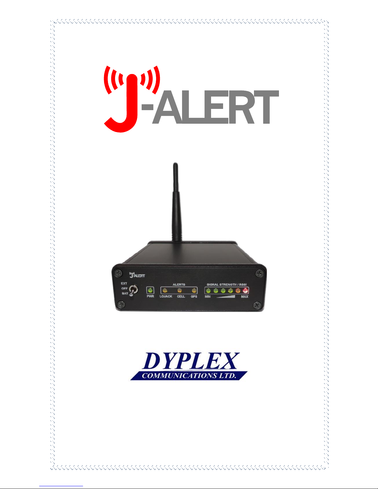
1- J-Alert Model JA2030 (EU & BR)
1- DC to DC convertor 12/24 to 5 v dc.
1- 220v AC to 5 v dc adaptor
1- Whip antenna
4- Pieces of 3M Dual Lock adhesive strips for unit mounting
1) Install J-Alert Model JA-2030 in a dry location either at a fixed
location or inside a vehicle to suit the requirements of your
operation. Antenna location should be at a line of level to
intercept signals from the suspect vehicle either at Dashboard or
Sun Visor level. Numerous configurations of equipment in
vehicles pre-exist therefore ensure antennas are located above
dashboard height and the device is secured to the vehicle in a
manner to prevent movement during driving maneuvers 4 strips
of 3M Dual Lock recloseable tape are provided, 2 for the J-Alert
and 2 for the surface to be attached to in the vehicle. The JA-
2030 is a small and light weight device allowing for the
application of double sided tape or Velcro for the purpose of
mounting the unit within the vehicle and this method also

___________________________________________________________
This document contains designs and other information which are the property of Dyplex
Communications Limited. Except for rights expressly granted by contract, this document may not,
in whole or in part, be duplicated, disclosed or used without the prior written permission of Dyplex
Communications Limited. pg. 9
allows for the JA-2030 unit to removed from the vehicle for the
purposes of taking on foot to confirm location of a jammer.
2) Insert the in-car power adapter or ac power adapter to
provide power via the rear USB charging port.
3) Turn on the J-Alert by switching the power switch to Ext for
use in a fixed location or in a vehicle where an external power
source is available or to Bat if taking the unit on foot using the
internal battery. (When powered the LED’s will all illuminate on
the face of the J-Alert and then after 2 sec. only the power LED
will be illuminated.
The device is now operational.
When a jamming device is detected operating in a Radio
Frequency band monitored by the J-Alert, the Led corresponding
to the band being jammed will illuminate on the front of the
device.

___________________________________________________________
This document contains designs and other information which are the property of Dyplex
Communications Limited. Except for rights expressly granted by contract, this document may not,
in whole or in part, be duplicated, disclosed or used without the prior written permission of Dyplex
Communications Limited. pg. 10
Jammer locating
(Mobile)
When jamming is detected, the Cell and GPS LED illuminates, an
audible alert will be heard and the received signal strength from
the jammer will be displayed. The received signal strength will
vary according to the proximity of the offender to the J-Alert.
When maximum Received Signal Strength is indicated on the
RSSI display, you can confirm the location of the jammer by
removing the J-Alert from the vehicle, switching the power to
battery and walk towards the offending vehicle or location.
Walk in the direction which indicates maximum signal.
(Fixed)
When jamming is detected using a J-Alert operating at a fixed
location (pinch point). Insert a 2.5 mm stereo plug into the rear
of the J-Alert relay out. Using the N/O (normally open) or the
N/C (normally closed) dry contacts you can trigger an external
device such as an alarm or a video camera to record the
offending vehicle or person.
•Using a transmitting cellphone within 24” of a J-Alert can
cause false sensing.

___________________________________________________________
This document contains designs and other information which are the property of Dyplex
Communications Limited. Except for rights expressly granted by contract, this document may not,
in whole or in part, be duplicated, disclosed or used without the prior written permission of Dyplex
Communications Limited. pg. 11
J-Alert Operation from a Highway Median

___________________________________________________________
This document contains designs and other information which are the property of Dyplex
Communications Limited. Except for rights expressly granted by contract, this document may not,
in whole or in part, be duplicated, disclosed or used without the prior written permission of Dyplex
Communications Limited. pg. 12
J-Alert Operation while mobile, Jammer vehicle
oncoming

___________________________________________________________
This document contains designs and other information which are the property of Dyplex
Communications Limited. Except for rights expressly granted by contract, this document may not,
in whole or in part, be duplicated, disclosed or used without the prior written permission of Dyplex
Communications Limited. pg. 13
J-Alert Operation while mobile, Jammer vehicle
approaching from behind

___________________________________________________________
This document contains designs and other information which are the property of Dyplex
Communications Limited. Except for rights expressly granted by contract, this document may not,
in whole or in part, be duplicated, disclosed or used without the prior written permission of Dyplex
Communications Limited. pg. 14
J-Alert Operation while stationary, jammer vehicle
approaching from behind a fixed structure

___________________________________________________________
This document contains designs and other information which are the property of Dyplex
Communications Limited. Except for rights expressly granted by contract, this document may not,
in whole or in part, be duplicated, disclosed or used without the prior written permission of Dyplex
Communications Limited. pg. 15
J-Alert confirmation of stopped Jamming vehicle

___________________________________________________________
This document contains designs and other information which are the property of Dyplex
Communications Limited. Except for rights expressly granted by contract, this document may not,
in whole or in part, be duplicated, disclosed or used without the prior written permission of Dyplex
Communications Limited. pg. 16
J-Alert Operation using a moving vehicle and then on
foot to confirm location of a Jamming vehicle

___________________________________________________________
This document contains designs and other information which are the property of Dyplex
Communications Limited. Except for rights expressly granted by contract, this document may not,
in whole or in part, be duplicated, disclosed or used without the prior written permission of Dyplex
Communications Limited. pg. 17
Support & Service
We offer extensive support and service for your new J-ALERT
device.
Please contact us at
Dyplex Communications Ltd
107 Woodbine Downs Blvd Unit 6
Toronto Ontario M9W6Y1 Canada
Phone: 416-675-2002
Fax: 416-675-1822
General email:info1@dyplex.com
Tech Support email dloignon@dyplex.com

___________________________________________________________
This document contains designs and other information which are the property of Dyplex
Communications Limited. Except for rights expressly granted by contract, this document may not,
in whole or in part, be duplicated, disclosed or used without the prior written permission of Dyplex
Communications Limited. pg. 18
Warranty
This product is warranted by Dyplex Communications Ltd. against
manufacturing defects in material and workmanship under normal use for one
(1) year from the date of purchase from Dyplex Communications.
Except AS PROVIDED HEREIN, Dyplex Communications Ltd. SHALL HAVE NO
LIABILITY OR RESPONSIBILITY
TO CUSTOMER OR ANY OTHER PERSON OR ENTITY WITH RESPECT TO ANY
LIABILITY, LOSS OR DAMAGE CAUSED DIRECTLY OR INDIRECTLY BY USE OR
PERFORMANCE OF THE PRODUCT OR ARISING OUT OF ANY BREACH OF THIS
WARRANTY, INCLUDING, BUT NOT LIMITED TO, ANY DAMAGES RESULTING
FROM
INCONVENIENCE, LOSS OF TIME, DATA, PROPERTY, REVENUE, OR PROFIT OR
ANY INDIRECT, SPECIAL, INCIDENTAL, OR CONSEQUENTIAL DAMAGES, EVEN IF
Dyplex Communications Ltd. HAS BEEN ADVISED OF THE POSSIBILITY OF SUCH
DAMAGES.
In the event of a product defect during the warranty period, ship the product
back to Dyplex Communications Limited will, at its option, unless otherwise
provided by law: (a) correct the defect by product repair without charge for
parts and labor; (b) replace the product with one of the same or similar design.
Repaired or replaced parts and products are warranted for the remainder of
the original warranty period. You will be charged for repair or replacement of
the product made after the expiration of the warranty period. This warranty
does not cover: (a) damage or failure caused by or attributable to acts of God,
abuse, accident, misuse, improper or abnormal usage, failure to follow
instructions, improper installation or maintenance, alteration, lightning or
other incidence of excess voltage or current; (b) any repairs other than those
provided by a Dyplex Communications Ltd. Service Facility; (c) consumables
such as fuses or batteries; (d) cosmetic damage; (e) transportation, shipping or
insurance costs.
Dyplex Communications Ltd.
#6-107 Woodbine Downs Blvd,
Toronto, Ontario Canada M9W 6Y1
Phone 416-675-2002
Table of contents