J.E. Adams 75000-SWL Series User manual

1
Model –75000-SWL*
Product Information Page 2
Important Safety Information Page 3
Specifications Page 3
Dimensions Page 4
Location & Preparation Page 5-6
Installation Page 7-23
- Vacuum ground or post mount Page 8-10
- Spring Centering Option Page 19-21
Trash Can Lock, Mat Rack Option Page 24-25
Maintenance Page 26
Parts List Page 27-31
REV 12-1-20

2
PRODUCT INFORMATION
Please take a moment to fill out the information below in order to aid us with any future sales
or service inquiries. Model number and serial number information can be found on the
serial tag located inside the control box and/or on the lower exterior of the can. Key
number can be found on the tag that comes attached to the keys. There may be more than
one key number depending on unit.
Please keep this information with your records.
MODEL#:____________________________
SERIAL#:____________________________
KEY NUMBER(S):_____________________
DATE PURCHASED:___________________
DISTRIBUTOR:_______________________
J.E. Adams Industries
1025 63rd Ave. S.W.
Cedar Rapids, IA 52404
1-800-553-8861
www.jeadams.com
REV 12-1-20

REV 12-1-203
“READ ALL INSTRUCTIONS BEFORE ASSEMBLING THIS PRODUCT”
Important Safety Information:
•Keep debris and objects away from boom to allow for smooth operation
•Do not use vac on wet surfaces.
•Use only as described in manual. Use only recommended attachments.
•Do not allow to be used as a toy. Close attention is necessary when used by or near children.
•Do not use with any opening blocked; keep free of dust, lint, hair and anything that may reduce
air flow.
•Keep hair, loose clothing, fingers, and all parts of body away from openings and moving parts.
•Do not use to pick up flammable or combustible liquids, such as gasoline, or use in areas where
they may be present.
•Do not pick up anything that is burning or smoking, such as cigarettes, matches, or hot ashes.
Specifications:
Weight: 140 lbs.
Available in power coat or 304 stainless steel post.
Powder coat finish has zinc rich primer base coat.
Swivel or non swivel functionality.

4 REV 12-1-20
DIMENSIONS:
All swivel booms have the same
dimensions for the pole and arch.
See picture for dimensions and
use dimensions when planning a
location to mount.

REV 12-1-205
Location and Preparation:
•Choose a location that is level for
the post to be installed.
•Make sure the location chosen will
not have any aerial disruption of
boom or interfere with any overhead
power lines, trees, etc.
•The area should have enough room
for the vacuum to be mounted next
to boom or mounted to the post and
be sure there is enough clearance
for cleanout doors to open.
•Below is a typical example of how the vacuum booms could be laid out. The
arrangement of the booms is up to the end user and should be determined
prior to construction.
•Please read the Installation Section of this manual to understand the boom
and vacuum configurations. Please take this into consideration when laying
out a site.
•Examine the location for the boom (s) to be mounted. Make sure that the
surface to be used is adequate to mount the booms. If new construction
please be sure to consult your contactor for footing adequate to handle the
mounting of the booms. See next page for footing specifications.
•For existing location see next page for footing information.

REV 12-1-206
**Consult with your local contractor and local building codes for foundation.
An example would be, for normal soil conditions a simple foundation would be a 30-inch diameter footing, 3’-0” deep
(in the ground), reinforced with (6) #7 (grade 60) vertical rebar equally spaced around the perimeter. Three inches
of clear distance between rebar and bottom/side edges of the foundation, 2-inches at top. Concrete minimum 28-
day compressive strength is 4,000 psi. Pole connecting anchor rods should have minimum 12-inches of
embedment.
Optional: 35000-79W-CFPA
j-hook kit can be purchased to
be used in footing. Kit will help
keep the proper spacing
needed to bolt pole to
concrete.
Baseplate
mount pattern.

Note:
For vacuums that are mounted next to pole please see subsequent pages for layout information. For information
regarding electrical requirements please refer to vacuum owners manual.
For vacuums that are mounted to the pole please also see subsequent pages for layout information. For information
regarding electrical requirements please refer to vacuum owners manual.
7 REV 12-1-20
INSTALLATION
- Place base over j-bolts and secure into place with nuts. Make sure post is level and shim if
necessary.
- Once post is secure, determine if vacuum will be mounted beside the post or mounted to
the post by looking at the next 3 pages of different possibly layouts:
Note: If mounting vacuum to the
post with U-bolt kit, make sure to
considerADA compliance and do not
exceed 48” height from ground to
coin drop or push button activation
device.

REV 12-1-208
Layout 1: Ground mounted vacuum next to pole.
This layout is for units that are to be mounted next to pole (follow instructions in vacuum owners
manual). The layout shown is just an example of a possible layout, and since the unit is mounted
next to the pole the configuration, can be anything that is preferred by customer.
Electrical:
Electric for this layout requires the stub-up to
be placed underneath the vac at customers desired location.
Electrical
under vac
Arch
Electrical stub
up under can.
Birds Eye View

REV 12-1-209
Layout 2 – Vacuum mounted on left side of post “BML-KIT”
This layout is for standard J.E.Adams units with post mount brackets added. The vacuum is mounted
on the left hand side of the pole. Using supplied hardware as pictured below. Vacuum height is up to
end user, but keep in mind ADA requirements of 48” max height to coin slot.
On back side of unit there is a hole in the
mounting bracket. There is a cover here to
access the electrical. Electrical stub up
location is up to the customer but is not
recommended to be ran up thru the pole.
FRONT
Mounting hardware
REAR OF POST

REV 12-1-2010
ARCH
On back side of unit there is a hole in the mounting bracket. There is a
cover here to access the electrical. Electrical stub up location is up to
the customer, but is not recommended to be ran up thru the pole.
Layout 3 –Rear mount vacuums.
This layout is for models 9217, 9218 and 9237 vacuums mounted to the pole. Unit has bracket mount
on front side of vacuum that mount to the back of pole. Use mounting kit 75000-2014Ato attach
vacuum to post. Vacuum height is up to end user, but keep in mind ADA requirements of 48” max
height to coin slot.
75000-2014A
mounting hardware

11
INSTALLATION cont.:
–Depending on how vacuum was mounted in previous steps, thread 2 inch vacuum hose into hose opening
of vacuum canister turning hose counter clockwise (model 9217 shown below). Thread until hose bottoms
out in plastic receiver inside vacuum canister.
–Proceed to then insert hose up through opening in main post and pull out all excess slack until there is only
a relaxed loop of hose left between the vacuum and the post. The goal is to not have excess slop and
not have the hose pulled so tight it binds or kinks.
REV 12-1-20
Thread hose
into inlet
counter-
clockwise.
Feed hose up
through post.
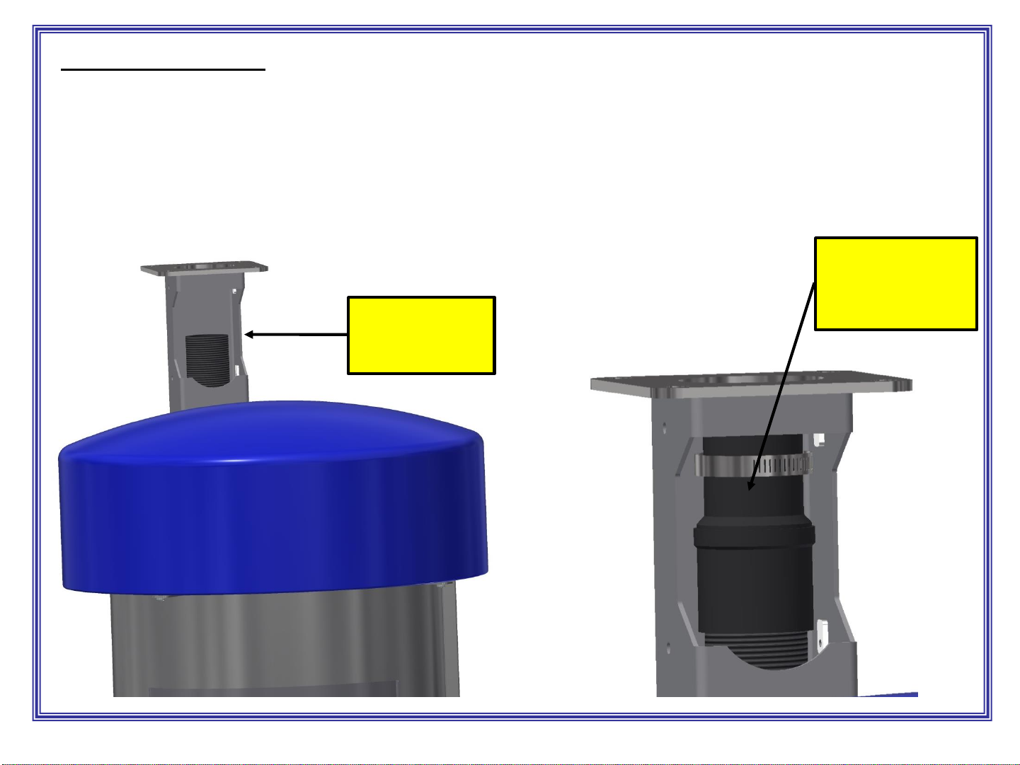
12
INSTALLATION cont.:
–Once hose slack is adjusted between the vacuum and the post, cut the upper hose off to be about midway
in post opening as pictured below.
–Thread swivel fitting/reducer onto hose and place hose clamp over small end for next steps.
REV 12-1-20
Cut hose off
about midway of
post opening.
Thread swivel
fitting/reducer onto
hose along with
hose clamp.
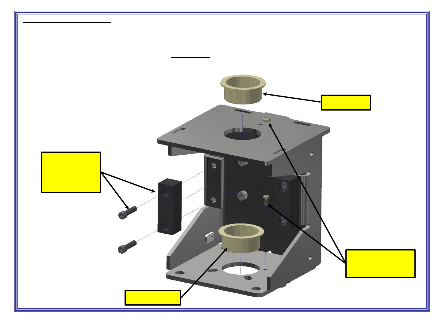
INSTALLATION cont.:
– Assemble upper bracket with (2) 2” bushings as pictured below and then install upper and
lower #10-24 Philips head screw to hold lower bushing in place.
–Assemble rubber bumpers to each side of unit using nuts and Allen bolts as shown.
13
#10-24 Philips
head screws
Bushing
REV 12-1-20
Bushing
Allen bolts,
rubber bumper,
nuts.
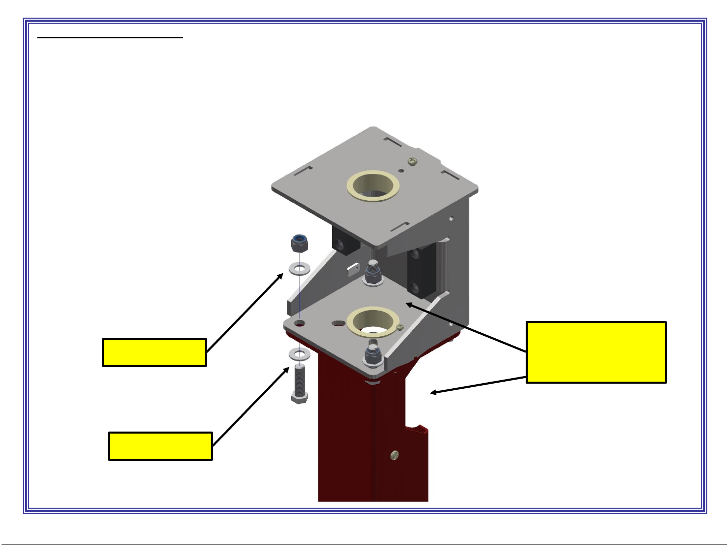
INSTALLATION cont.:
–Assemble upper bracket to post using the 4 bolts, nuts and washer provided, as pictured
below. Note orientation of upper bracket opening vs. lower post opening.
–If unit is ordered with spring centering device include spring stop in this assembly (see
page 15).
14 REV 12-1-20
Bolt & washer.
Nut & washer. Opening of upper
bracket and post are
opposite one another.

15
INSTALLATION cont.:
- Using two people, insert end of arch into top plastic bearing/bushing. Once through the
upper bearing, manually hold the shaft collar clamp in place and slide arch into it, and
then into the lower bearing/bushing. Do not tighten collar clamp at this time. !!Two
person task, one to hold arch assembly, other to guide arch into place!!
- Add safety retaining bolt, spacer, and washer.
-NOTE: If adding arch/spring centering kit,
now is the ideal time to do it. Please see
manual chapter on spring centering device.
REV 12-1-20
Shaft collar
clamp.
Safety bolt,
spacer and
washer.

16
INSTALLATION cont.:
-Slide swivel fitting/coupler with clamp over the 2” tube that was just installed. Tighten
clamp.
- Install lower cover over opening.
REV 12-1-20
Swivel fitting
Clamp
2” tube/arch
Install cover

INSTALLATION: FIXED BOOM OPTION (no swivel)
17
Simply install shaft collar pin into opening as shown. Adjust arch to whatever angle/location desired
and securely tighten shaft collar to tube/arch.
Install upper cover when finished.
REV 12-1-20
Lower pin into hole. Leave
about ½” between collar and
bottom of housing.
Adjust arch to
desired angle before
tightened collar.
Install cover.

INSTALLATION: SWIVEL BOOM
18
3rd option adding
addition Stop Collar
(75000-655W)
There are 3options for swivel boom
1. Remove all stop collars and allow arch to freely swivel 360 degrees.
2. Mount standard factory stop collar (75000-657W) which will limit rotation to 180 degrees.
3. Add 2nd collar stop collar (75000-655W) to limit rotation to less than 180 degrees.
Note, orientation of the arch is totally independent of the orientation of the stop collars as they will
clamp on the arch tube at any orientation.
Note centered
vertically on
rubber stops
In this example,
two stop collars
will limit arch to
90 degrees of
rotation.
REV 12-1-20
Install cover.
Shaft Stop Collar.
75000-657W

Arch centering device option: p/n 75000-220
19
Torsion
Spring.
75000-427
- Arch Centering Option (75000-220) is a kit that will bring arch to a
home position when swung to either side of home. Maximum articulation
for this option is 180 degrees, 90 degrees one direction 90 degrees
the other direction, no exceptions. To install requires removal of arch.
- First remove pole access cover and bracket access cover. Remove
swivel fitting from end of arch pipe (page 16) and stop collar on arch if
one is installed. Remove suction hose from end of arch.
- Using tall step ladder placed at middle of arch lift arch straight up and
remove from bracket. Two people required!!
- Remove two bracket mount nuts and washers on open side of main
bracket, place Spring Centering Base (75000-426W) over mounting bolts
and replace washers and nuts, torque bolts to 30 ft*lbs.
- Using WD-40 or similar rust inhibitor coat spring prior installation.
Primary purpose is to prevent rust, secondary is lubrication.
- Place torsion spring (75000-427) centered over bushing on inside of
bracket. Replace arch carefully (two people required), keep arch
relatively straight to prevent damage to bushings. Replace stop bolt,
washer, and spacer on top of bracket.
- With spring now captured over arch and Spring Centering base in place
you can proceed to spring preloading on next page.
Temporarily remove
these two nuts and
washers to install plate.
Stop bolt,
washer and
spacer.
Spring Center
Base. 75000-426W
REV 12-1-20

20
Centering option cont.:
- Caution…. Next step requires preloading the torsion spring. Keep all body parts away from spring and it’s
path if released. Wear eye protection while working with spring. Bottom spring leg should be positioned against
base of pin on Spring Center bracket (see picture #2). Note preloading is done by turning spring clockwise.
-Using ¾” box end wrench hook end of spring that’s to the rear of bracket with box end of wrench, pry spring
approximately 90 degrees. Then using 3/8” drive 7/16” deep well socket with extension place socket over end of
spring. Make sure to engage spring leg it’s entire length before removing ¾” box end wrench.
-With deep well socket fully engaged with spring leg, the ¾” box end wrench can be slid over socket and
removed. Continue rotating spring towards the front of the bracket using deep well socket and extension as
leverage. Be careful to keep full engagement of spring leg with socket while rotating leg to the front.
- Once to Center pin lift spring leg up and over center pin. Pull down on leg and use a tool to push spring coils
down on all sides around arch if needed. Important spring be resting against Spring Center bracket.
- Remove socket by pulling off leg. Spring should be captured by pin on Spring Center bracket and is now
preloaded.
Pic 6
Pic 5
Pic 2 Pic 3
Pic 4
Pic 1
REV 12-1-20
Table of contents
Other J.E. Adams Dehumidifier manuals


