J.E. Adams 9670 User manual

REV A 8-26-20111
Models - 9670, 9670-F
Page 2 Product Information
Page 3 Specifications
Page 4 Important Safety Instructions
Page 5 Product Dimensions
Page 6-8 Installation
Page 9 Timer Set-Up
Page 10 Operating Instructions & Maintenance
Page 11 Troubleshooting
Page 12-13 Parts List & Wiring Diagrams

REV A 8-26-20112
PRODUCT INFORMATION
Please take a moment to fill out the information below in order to aid us with any future sales
or service inquiries. Model number and serial number information can be found on the
serial tag located inside the control box and/or on the lower exterior of the can. Key
number can be found on the tag that comes attached to the keys. There may be more than
one key number depending on unit.
Please keep this information with your records.
MODEL#:____________________________
SERIAL#:____________________________
KEY NUMBER(S):_____________________
DATE PURCHASED:___________________
DISTRIBUTOR:_______________________
J.E. Adams Industries
1025 63rd Ave. S.W.
Cedar Rapids, IA 52404
1-800-553-8861
www.jeadams.com

REV A 8-26-20113
Specifications
Unit specifications: 9670, 9670-F
Voltage: 120vac, 60hz
Amperage: (1) 10 amp service is required for this unit
Compressor: ¾ hp, twin cylinder
Timer: SSAC
Weight: 68lbs with dome
Locks: (2) High Security Medeco cam lock
DUTY CYCLE: 4 minutes on, 4 minutes off. Optional accessories:
NOTE: “UNIT INTENDED FOR COMMECIAL USE ONLY”
Wall mount
pedestal
8819-60
Lock bar kit
9670-24A
Floor mount
pedestal
8819-50

REV A 8-26-20114
IMPORTANT SAFETY INSTRUCTIONS
When using an electrical appliance, basic precautions should always be followed, including the following:
READ ALL INSTRUCTIONS BEFORE USING (THIS APPLIANCE)
WARNING – To reduce the risk of fire, electric shock, or injury:
• Use only as described in manual. Use only manufactures recommended attachments.
• Do not allow to be used as a toy. Close attention is necessary when used by or near children.
• Do not put any object into openings. Do not use with any opening blocked; keep free of dirt and anything that may reduce
flow.
• Keep hair, loose clothing, fingers, and all parts of body away from openings and moving parts.
• Do not use near flammable or combustible liquids, such as gasoline, or use in areas where they may be present.
• Do not use near anything that is burning or smoking, such as cigarettes, matches, or hot ashes.
SAVE THESE INSTRUCTIONS
• Installation Instructions:
• Determine location to mount unit (“DANGER” “THIS EQUIPMENT INCORPORATES PARTS SUCH AS SWITCHES,
MOTORS, OR THE LIKE THAT TEND TO PRODUCE ARCS OR SPARKS THAT CAN CAUSE AN EXPLOSION.
WHEN LOCATED IN GASOLINE-DISPENSING AND SERVICE STATIONS INSTALL AND USE AT LEAST 20 FEET (6
M) HORIZONTALLY FROM THE EXTERIOR ENCLOSURE OF ANY DISPENSING PUMP AND AT LEAST 18 INCHES
(450 MM) ABOVE A DRIVEWAY OR GROUND LEVEL.”
• Run electrical service to that location (NOTE UNIT HAS WIRE PROVIDED UNDERNEATH DOME TO CONNECT
INCOMING POWER SUPPLY)
• Grounding Instructions: This appliance must be connected to a grounded metal, permanent wiring system; or an
equipment-grounding conductor must be run with the circuit conductors and connected to the equipment-grounding
terminal or lead on the appliance.
• All local and national electric codes must be followed for installation and use.
• Licensed electricians are recommended for installation.

REV A 8-26-20115
PRODUCT DIMENSIONS
.
Wall mount
pedestal
option.
Floor mount
pedestal
option.

REV A 8-26-20116
Pedestal mounting information:
Installation bolt
pattern. If mounting
to hollow concrete
block, proper
hardware must be
used (5/16"). Ex –
split sleeve wall
anchor, toggle bolts,
etc. Solid concrete
can use red-head
type anchors.
Floor
mount
pedestal
Wall
mount
pedestal

REV A 8-26-20117
.
Route electrical through
pedestal and up through center
of machine. Allow enough extra
wire on top to tie into the factory
wiring pictured on next page.
Once pedestal is
mounted, set air
machine onto
pedestal and open
door to access inside
of machine.
Bolts will line up
through bottom of
cabinet. Attach
with supplied
hardware
(4 nuts).

REV A 8-26-20118
NOTE: AIR MACHINE SHOULD BE INSTALLED PER LOCAL ELECTRICAL CODES BY QUALIFIED
ELECTRICIAN.
Wire nut 120VAC black to black, white
to white.
Add green ground wire to stud
provided.

REV A 8-26-20119
Programming:
The below timer pictured is the standard SSAC model that allows the end user to select the "coins to start" and
the "time per coin" by settings series of dip switches. The number of "coins to start" dip switch is how many
quarters are needed to make the machine come on. In the below example, the "one coin" dip is selected which
makes the unit come on with one coin. The "time per coins" will then need to be set, but a good rule of thumb
would be 4 minutes which requires dip switches 3.2 and .8 to be set to on. This scenario means 1 quarter will
provide 4 minutes of vacuum time. The time per coin setting can be modified as desired by simply adding or
subtracting time. If the operator would later decide to increase the cost of the unit to "2" quarters, the 2 dip
switch would need to be in the on position (all other off) and the time dip switches would need to have the 1.6
and 0.4 dips selected. This would allow 2 minutes of time for each quarter for a total of 4 minutes for two
quarters. Time in minutes/per coin dip switch settings:
0.1 = 6 seconds
0.2 = 12 seconds
0.4 = 24 seconds
0.8 = 48 seconds
1.6 = 96 seconds
3.2 = 192 seconds
6.4 = 384 seconds

REV A 8-26-201110
Machine Operating Instructions:
1) Read safety instructions on previous pages.
2) Insert coins to start.
4) Compressor will start.
5) For best results, remove valve stem covers on all tires before depositing money.
6) Hang hose up when finished.
Maintenance:
• All servicing of machine should be conducted by an authorized service representative!
• Periodically inspect hose, chuck, and chuck washer for wear or fatigue.
• Every month remove filter from compressor and clean.
• Periodically inspect electrical wires and connections for wear or fatigue.
• Clean canister with a stainless steel cleaner as needed.
• Decals can be cleaned with mild soap and water.
• Replacement parts can be ordered through JE Adams or your nearest dealer.
WHEN PERFORMING MAINTENANCE OR TROUBLE-SHOOTING, TURN POWER OFF! QUALIFIED
PERSONNEL ONLY!

REV A 8-26-201111
Troubleshooting:
Problem Possible cause Solution
Breaker inside fuse panel is not in the on position. Turn breaker on.
No power to machine. Check incoming power line voltage.
Machine power switch is not on. Remove dome and flip switch.
Loose connection. Check incoming power connection.
Air is leaking from unit somewhere. Turn power off to unit, apply chuck to air
source with at least 30lbs of pressure and
listen carefully for leaks inside cabinet or air
hose.
Chuck washer is worn out? Replace rubber washer inside chuck with JE
Adams PN 8533-3CW.
Wrong size breaker or other components running on
same circuit. Install correct breaker for compressor and
make sure line is a dedicated power source.
Compressor or timer might be shorted out? Isolate problem component and replace if
necessary.
Check key components to isolate failure:
Timer: Verify proper input voltage. Activate
timer. If no output voltage is present when
timer should be active, replace timer.
Coin mech: If using a mechanical coin mech,
remove the wires leading to the timer from the
coin mech and tap the together one time for
each coin necessary to start the timer. If
machine starts, replace the coin mech.
Unit is not powered.
Unit keeps tripping
breaker from
incoming power
source
Unit runs but will not
inflate tire.
Unit will not start Possible component failure
ALWAYS DISCONNECT POWER BEFORE TROUBLESHOOTING!!
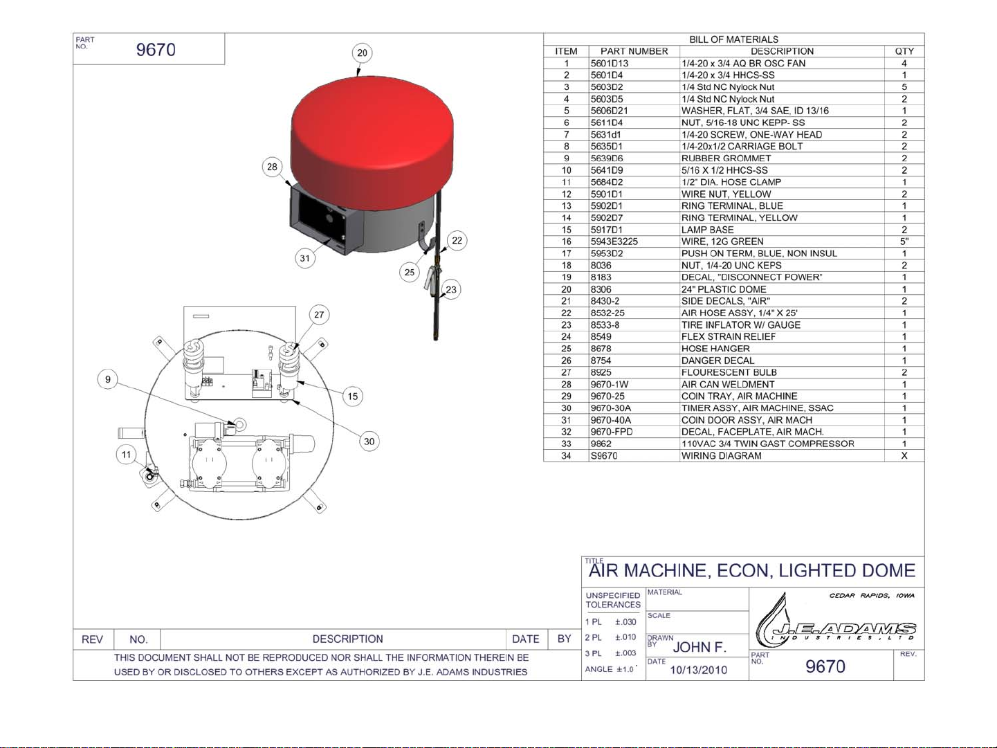
REV A 8-26-201112

REV A 8-26-201113
This manual suits for next models
1
Table of contents
Other J.E. Adams Dehumidifier manuals


