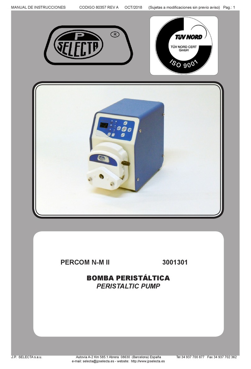
J.P. SELECTA PR-2004 User manual

MANUAL DE INSTRUCCIONES CODIGO 80418 REV 0 11/2021 Pag.: 1
J.P. SELECTA s.a.u. Autovía A-2 Km 585.1 Abrera 08630 (Barcelona) España Tel 34 937 700 877 Fax 34 937 702 362
BOMBA PERISTÁLTICA PR-2004
PERISTALTIC PUMP PR-2004
4129051

INSTRUCTION MANUAL CODE 80418 REV 0 11/2021 Page: 2
J.P. SELECTA s.a.u. Autovía A-2 Km 585.1 Abrera 08630 (Barcelona) España Tel 34 937 700 877 Fax 34 937 702 362
Indice
1. Información General ...................................................................................................................................3
2. Lista de Embalaje ........................................................................................................................................3
3. Accesorios ...................................................................................................................................................3
4. Especicación Técnica.................................................................................................................................3
5. Descripción del Equipo ................................................................................................................................4
6. Instalación...................................................................................................................................................4
7. Operación ...................................................................................................................................................4
8. Ajustes de los parámetros ..........................................................................................................................7
9. Conguración ..............................................................................................................................................9
10. Calibración...............................................................................................................................................10
11. Ajustes.....................................................................................................................................................11
12. Mantenimiento ........................................................................................................................................13
13. Garantía...................................................................................................................................................13
Aviso a los usuarios.......................................................................................................................................13
1. General information ..................................................................................................................................14
2. Packing list ................................................................................................................................................14
3. Accessories................................................................................................................................................14
4. Technical specications ............................................................................................................................14
5. Equipment Description..............................................................................................................................15
6. Installation................................................................................................................................................15
7. Operación .................................................................................................................................................15
8. Parameters settings .................................................................................................................................18
9. Conguration.............................................................................................................................................20
10. Calibration...............................................................................................................................................21
11. Settings ...................................................................................................................................................22
12. Maintenance............................................................................................................................................24
13. Warranty .................................................................................................................................................24
Notice to customers ......................................................................................................................................24

MANUAL DE INSTRUCCIONES CODIGO 80418 REV 0 11/2021 Pag.: 3
J.P. SELECTA s.a.u. Autovía A-2 Km 585.1 Abrera 08630 (Barcelona) España Tel 34 937 700 877 Fax 34 937 702 362
Bomba peristáltica PR-2004 4129051
Manual de instrucciones 80418
3. Accesorios
Pedal de Control a Distancia 1001046
Conector de control externo (DB-15) RS485
4. Especicación Técnica
Modelo: 4129051
Rango de velocidad: 0,1 a 600rpm
Resolución de velocidad: 0,1rpm
Método de control: Pantalla TFT
Control externo: Start / Stop, dirección, control de
velocidad (opcional), comunicación
serial RS485
Fuente de alimentación: AC 220V±10%, 50Hz / 60Hz
Consumo: <50W
Condiciones de trabajo: Temperatura 0-40ºC
Humedad relativa <80%
Dimensiones de transmisión (LaxAnxAl): 254x184x145mm
Peso de la bomba: 4,8Kg
Tasa de IP: IP31
Rango del caudal: 0,0015 a 2280,l/min
1. Información General
• Manipular el paquete con cuidado. Desembalarlo y comprobar que el con-
tenido coincide con lo indicado en el apartado de la “Lista de embalaje”. Si se
observa algún componente dañado o la ausencia de alguno, avisar rápidamente
al distribuidor.
• No instalar ni utilizar el equipo sin leer, previamente, este manual de instruc-
ciones. Estas instrucciones forman parte inseparable del equipo y deben estar
disponibles a todos sus usuarios.
• Consultar cualquier duda al servicio técnico.
• No utilizar el equipo en atmosferas explosivas, inamables ni corrosivas.
2. Lista de Embalaje
4.1 Funciones principales y características
A - Interruptor principal
B - Conector control externo (RS485)
C - Fusible
D - Conector de alimentación
A
B
C
D

INSTRUCTION MANUAL CODE 80418 REV 0 11/2021 Page: 4
J.P. SELECTA s.a.u. Autovía A-2 Km 585.1 Abrera 08630 (Barcelona) España Tel 34 937 700 877 Fax 34 937 702 362
5. Descripción del Equipo
- Bomba peristáltica con pantalla LCD a color de 3,5 pulgadas. Funcionamiento
de la función de visualización del estado en tiempo real, que muestra el ujo y
la velocidad de rotación del motor al mismo tiempo, control de la pantalla táctil.
- Con función de calibración inteligente, que podría calibrar las tasas de ujo y el
volumen de infusión; Adecuado para la transferencia de uidos de alta precisión.
- Función de ahorro de datos del usuario: puede guardar 9 conjuntos de datos
para los clientes.
- La función de control de ángulo preciso garantiza una distribución y una medi-
ción de alta precisión.
- Función de memoria able y segura disponible en caso de apagado.
6. Instalación
Colocar la bomba sobre una supercie plana, horizontal y nivelada, pro-
curando dejar un espacio libre de 10 cm. por la parte posterior y por los
laterales del equipo.
No utilizar el equipo para el secado o tratamiento de productos
que puedan desprender vapores o formar mezclas explosivas o
inamables.
Asegúrese que el equipo se conecta a una tensión de red que coin-
cide con la indicada en la placa de características.
No utilice el equipo sin estar conectada la toma de tierra.
Si cambia la clavija de conexión tenga en cuenta lo siguiente:
Cable azul: Neutro.
Cable marrón: Fase.
Cable amarillo/Verde: Tierra.
7. Operación
7.1 Teclas de funciones
1. Tecla Home
2. Tecla Start/Pause
3. Tecla dirección
4. Tecla maxima velocidad
5. Pantalla
¡ATENCIÓN! IMPORTANTE PARA SU SEGURIDAD

MANUAL DE INSTRUCCIONES CODIGO 80418 REV 0 11/2021 Pag.: 5
J.P. SELECTA s.a.u. Autovía A-2 Km 585.1 Abrera 08630 (Barcelona) España Tel 34 937 700 877 Fax 34 937 702 362
1. Tecla Home
Cuando el usuario entre en otra pantalla puede pulsar esta tecla para regresar
rápidamente a la pantalla principal sin guardar los datos.
2. Tecla Start/Pause
Tecla para controlar el funcionamiento y parada del equipo. La primera vez que
se pulse esta tecla, la unidad se pondrá en funcionamiento, al volver a pulsar se
detendrá y si se pulsa por tercera vez se reanudará el funcionamiento.
3. Tecla Dirección
Tecla para cambiar la dirección de giro de la unidad.
4. Tecla Máxima velocidad
También conocida como tecla de vaciado y limpieza. Pulse esta tecla para que el
equipo funcione a máxima velocidad, y pulse nuevamente para volver al estado
original.
7.2 Áreas en el panel de control
------> Área de menú gráco
------> Área de introducción de los parámetros
------> Área de valores de los parámetros
1. Área de menú gráco: Conguración y operación de los datos / Bloqueo y
desbloqueo / Sonido encendido/apagado / Control remoto.
2.Área de introducción de los parámetros: Volumen de llenado / Tiempo de lle-
nado / Tiempo de pausa / Nº de copia.
3. Área de visualización de parámetros de estado: Estos son los parámetros que
se muestran: Instrucciones de animación del funcionamiento / Dirección / Mod-
elo cabezal de la bomba / Modelo tubos de la bomba / Velocidad de rotación /
Tasa de ujo / Volumen de llenado /Nº de llenado.
1. Conguración del sistema
2. Almacenamiento de datos
3. Bloqueo /desbloqueo del panel para evitar el funcionamiento
4. Sonido encendido / apagado
5. Modo control remoto
Volumen llenado Tiempo de pausa
Tiempo llenado Nº de copia
Tecla dirección Modelo cabezal Velocidad rotación Volumen llenado
Dirección / Lleno Modelo tubo Flujo Nº llenado

INSTRUCTION MANUAL CODE 80418 REV 0 11/2021 Page: 6
J.P. SELECTA s.a.u. Autovía A-2 Km 585.1 Abrera 08630 (Barcelona) España Tel 34 937 700 877 Fax 34 937 702 362
7.3 Menú gráco

MANUAL DE INSTRUCCIONES CODIGO 80418 REV 0 11/2021 Pag.: 7
J.P. SELECTA s.a.u. Autovía A-2 Km 585.1 Abrera 08630 (Barcelona) España Tel 34 937 700 877 Fax 34 937 702 362
8. Ajustes de los parámetros
Instrucciones para rellenar el área de los parámetros:
8.1 Congurar el volumen de llenado
1. Haga clic en el valor de cantidad de llenado, y aparecerá el teclado pequeño.
2. Haga clic en el rango de volumen 0.001ml-9999L (mostrará el valor máximo
y el mínimo para el uso del cabezal de la bomba y los tubos. Sólo se podrá
introcudir el valor en este rango).
3. Unidades: ml / L
4. Cuando se detiene el llenado, puede hacer clic en el valor de entrada, pero
si la unidad está en funcionamiento, no podrá clicar en el valor de entrada.
5. Congurar el teclado :
Filling volume:
Max:9999L Min:0.001ml
124.5 ml
1 2 3 C
4 5 6 U
7 8 9 Esc
0 . OK
Enter the filling
volume you want
Filling time
:
Max:9999min Min:0.1s
234.5 s
1 2 3 C
4 5 6 U
7 8 9 Esc
0 . OK
Filling time
range
1.Click the Filling time quantity value, will show a small
5.Set the keyboard:
4.With countdown function
2.Range: 0.1sec - 9999min; Unit: sec, min
3.When the filling stop you can click on the input value, but if
Set the filling time
keyboard, then input your filling time
the drive running, you can't click on the input value
Filling volume setting interface
Filling time setting interface
6
Delete
Unit setup
Exit
Confirm
U s e o f d i s p e n s i n g t y p e o f c r a w l i n g p u m p
Delete
Unit setup
Exit
Confirm
8.2 Congurar el tiempo de llenado
1. Haga clic en el valor de cantidad de llenado, y aparecerá el teclado pequeño
y después introduzca el tiempo de llenado.
2. Rango: 0,1seg - 9999min; Unidades: seg, min.
3. Cuando se detiene el llenado, puede hacer clic en el valor de entrada, pero
si la unidad está en funcionamiento, no podrá clicar en el valor de entrada.
4. Con función de cuenta atrás.
5. Congurar el teclado:
Filling volume:
Max:9999L Min:0.001ml
124.5 ml
1 2 3 C
4 5 6 U
7 8 9 Esc
0 . OK
Enter the filling
volume you want
Filling time
:
Max:9999min Min:0.1s
234.5 s
1 2 3 C
4 5 6 U
7 8 9 Esc
0 . OK
Filling time
range
1.Click the Filling time quantity value, will show a small
5.Set the keyboard:
4.With countdown function
2.Range: 0.1sec - 9999min; Unit: sec, min
3.When the filling stop you can click on the input value, but if
Set the filling time
keyboard, then input your filling time
the drive running, you can't click on the input value
Filling volume setting interface
Filling time setting interface
6
Delete
Unit setup
Exit
Confirm
U s e o f d i s p e n s i n g t y p e o f c r a w l i n g p u m p
Delete
Unit setup
Exit
Confirm

INSTRUCTION MANUAL CODE 80418 REV 0 11/2021 Page: 8
J.P. SELECTA s.a.u. Autovía A-2 Km 585.1 Abrera 08630 (Barcelona) España Tel 34 937 700 877 Fax 34 937 702 362
8.3 Congurar el tiempo de parada
1. Haga clic en el valor de la cantidad de tiempo de parada, y aparecerá el
teclado pequeño, y después introduzca el intervalo de tiempo.
2. Rango de tiempo: 0,1seg-9999min
3. Unidades: seg (segundos), min (minutos)
4. El valor del tiempo de parada es para establecer el intervalo de tiempo
entre dos rellenos; solo se puede congurar cuando se detiene el llenado.
5. Cuando se detiene el llenado, no se puede ajustar el tiempo de parada.
6. Con función de cuenta atrás.
7. Congurar el teclado:
Pause time:
Max
:9999
min
Min
:0.1
s
124.5 s
1 2 3 C
4 5 6
7 8 9 Esc
0 . OK
Pause time
range
1. Click the Stop Time quantity value, will show a small
keyboard, then input your interval time
7. Set the keyboard:
Set the Stop Time
5. During the filling period, the stop time cannot be set
3. Units:sec(second), min (minute)
6. With countdown display function
2. Time Range: 0.1sec-9999min
4. Stop time value is to set the interval time between two
fillings; it can be only set when the filling is stopped.
2. Range: 0-9999 times, 0 on behalf of the infinite time
1. Click on the Filling Number quantity value, will show a
small keyboard, and then input your filling number
3. When the filling stop you can click on the input value, but if
the drive running, you can't click on the input value
Set the Filling Number
4. Set the keyboard:
Pause time setting interface
7
U
U s e o f d i s p e n s i n g t y p e o f c r a w l i n g p u m p
Delete
Unit setup
Exit
Confirm
8.4 Congurar el número de llenado
1. Haga clic en el valor de la cantidad de llenado, y aparecerá el teclado
pequeño e introduzca después su número de llenado.
2. Rango: 0-9999 veces, 0 para indicar tiempo innito.
3. Cuando se detiene el llenado, puede hacer clic en el valor de entrada, pero
si la unidad está en funcionamiento, no podrá clicar en el valor de entrada.
4. Congurar el teclado:
Copy number:
Max
:9999
t
Min
:0
t
1241t
1 2 3 C
4 5 6
7 8 9 Esc
0 . OK
Copy number
range
Select the current use of the pump head models
the pump head selection menu; then choose your current pump head. Click
Pump tube selection menu, to choose the suitable model)
Turn on the power, enter the initial interface, Click Settings, enter the setup
change the tubing which the same pump head use, you can just enter the
menu; Click System Set, enter the system setup menu; Click Tube, enter
menu; Click System Set, enter the system setup menu; Click Head, enter
PUMP TUBE SELECTION
Turn on the power, enter the initial interface, Click Settings, enter the setup
Enter, save and exit;Click Cancel, exit without saving.
the pump tube selection menu; then choose your current pump Tube. Click
Select the current use of the pump tubing models
Enter, save and exit;Click Cancel, exit without saving. (if you just want to
PUMP HEAD SELECTION
etc.); DG series pump head's tubing selections depend on the inside diameter of the tube (for
diameter, to ensure the calibration accuracy. Pump heads and the application of hose are
described in details of the manual.
example, 2*1 tube, should choose the 2.00). Set values most close to the actual using hose inside
NOTED: YZ series pump heads' tubing selections depend on the model (such as 13#/14#
-
-
-
-
-
-
-
Pump Menu operation method
Copy number setting interface
8
Product Introduction
Intelligent dispensing type peristaltic pumps
Delete
Exit
Confirm
SELECCIÓN DEL TUBO DE LA BOMBA
Seleccione el uso actual de los modelos de tubos de la bomba.
Encienda la alimentación, entre en la pantalla inicial, haga clic en Congu-
ración, entre en el menú de conguración; Haga clic en Conguración del
sistema, entre en el menú de conguración del sistema; Haga clic en Tubo,
y entre en el menú de selección del tubos de la bomba; luego a continu-
ación el tubo actual de la bomba. Haga clic en Entrar, guardar y salir; Haga
clic en Cancelar, para salir sin guardar. (Si solo desea cambiar el tubo que
usa el mismo cabezal de bomba, puede entrar en el menú de selección del
tubo de la bomba para elegir el modelo adecuado).

MANUAL DE INSTRUCCIONES CODIGO 80418 REV 0 11/2021 Pag.: 9
J.P. SELECTA s.a.u. Autovía A-2 Km 585.1 Abrera 08630 (Barcelona) España Tel 34 937 700 877 Fax 34 937 702 362
9. Conguración
Entrada de control externo
Seleccione los parámetros de entrada de control externo.
Encienda la alimentación, entre en la pantalla principal, haga clic en Congu-
ración, entre en el menú de ajustes; Haga clic en Conguración del sistema,
entre en el menú y haga clic en Entrada de control externo; Selecciones los
elementos de control adecuados; Haga clic en Enter, para guardar y salir;
Haga clic en Cancelar para salir sin guardar.
Conguración de comunicación
Seleccione los parámetros de comunicación de la bomba.
Desde la pantalla inicial, pulse el icono de Sistema para entrar en el menú
conguración; Haga clic en Conguración del sistema para entrar en el menú
de ajustes del sistema; Haga clic en Conguración de comunicación para
entrar en el menú; Seleccione los elementos de control apropiados (incluy-
endo: dirección de transmisión, dirección local, velocidad en baudios); Haga
clic en Enter para guardar y salir o en Exit para salir sin guardar.
La bomba tiene 485 interfaces de bus de comunicación en serie para conec-
tarse al ordenador principal (ordenador, PLC, SCM). El PC puede conectar
simultáneamente hasta 30 dispositivos con 485 funciones de interfaz de bus
de comunicación en serie; cuando se utiliza con múltiples dispositivos para
comunicarse con el ordenador host, deberemos conocer el número de la
máquina de cada dispositivo. Esta ID del dispositivo es el único número que
debería conectarse entre sí, y cada dispositivo tiene un número diferente. El
valor predeterminado de fábrica para cada bomba es “1”; se puede restabl-
ecer mediante control remotoa través del ordenador host o cambiando de
forma manual desde el menú de conguración. Cambie los siguientes pasos:
Pulse la tecla Enter para entrar en las opciones del menú, mueva el cursor
para ajustar los parámetros, y pulse Enter para entrar, busque la opción del
número de la máquina, entre y ajústelo.
(Ver capítulo 11.2 Ajustes > Control externo)
Ajustes de succión
Seleccione los parámetros de succión.
Encienda el equipo, entre en la pantalla inicial, haga clic en Conguración,
entre en el menú de ajustes; Haga clic en Conguración del sistema, entre
en el menú de ajustes, haga clic en Succión y entre en el menú; Escoja los
elementos de control adecuados (dirección y velocidad); Haga clic en Enter,
para guardar y salir o en Cancelar para salir sin guardar.
Icono de engranaje
Muestra el estado de funcionamiento de la bomba.
Cuando la bomba está en funcionamiento, el engranaje se moverá. Si la
bomba se detiene, también el engranaje.
Icono de dirección y velocidad máxima
Pulsando las teclas de echa se cambiará la dirección de funcionamiento
del motor.
Al pulsar la tecla Full Speed (Máxima velocidad), se mostrarán echas dobles,
que indicarán que el motor está funcionando a máxima velocidad.
Otros valores de estado mostrados
- Cabezal de la bomba
- Tubos de la bomba
- Pantalla de velocidad, las unidades son rpm. El sistema lo muestra au-
tomáticamente según el ujo.
- Tiempos de llenado mostrados como función acumulativa.
- Pantalla de volumen de uido real con función de cuenta atrás.
- Visualización del tiempo de llenado real con función de cuenta atrás.

INSTRUCTION MANUAL CODE 80418 REV 0 11/2021 Page: 10
J.P. SELECTA s.a.u. Autovía A-2 Km 585.1 Abrera 08630 (Barcelona) España Tel 34 937 700 877 Fax 34 937 702 362
Interface analysis correction guide
for the crawling pump
11
Actual filling volume interface
Countdown interface
The interface shows the current using pump tube, conveying fluid
volume and advice calibration volume. If the suggested calibration
volume is big, you can reduce the value according to the filling
condition; input the calibration value and then click Next, enter the
calibration menu, or click Exit Back to previous menu.
U s e o f d i s p e n s i n g t y p e o f c r a w l i n g p u m p
Running:
Time reamining:85.41s
Cancel
(Tested repeatedly input the results)
Calibration Data:
Liquid volume 1:
Liquid volume 2:
Liquid volume 3:
321.3ml
321.3ml
321.3ml
Back Next Exit
La pantalla mostrará el tubo de la bomba que se esté utilizando actual-
mente, transportando el volumen de uido y recomendando el volumen de
calibración. Si el volumen de calibración sugerido es alto, se podrá reducir
el valor según la condición de llenado. Introduzca el valor de calibración y
haga clic en Siguiente (Next), y entre en el menú de Calibración, o pulse
sobre Salir (Exit o Back) para regresar al menú anterior.
Interface analysis correction guide
for the crawling pump
11
Actual filling volume interface
Countdown interface
The interface shows the current using pump tube, conveying fluid
volume and advice calibration volume. If the suggested calibration
volume is big, you can reduce the value according to the filling
condition; input the calibration value and then click Next, enter the
calibration menu, or click Exit Back to previous menu.
U s e o f d i s p e n s i n g t y p e o f c r a w l i n g p u m p
Running:
Time reamining:85.41s
Cancel
(Tested repeatedly input the results)
Calibration Data:
Liquid volume 1:
Liquid volume 2:
Liquid volume 3:
321.3ml
321.3ml
321.3ml
Back Next Exit
La bomba se detendrá automáticamente una vez nalizada la conguración.
También puede hacer clic en cancelar (Cancel) para anular y volver a la
pantalla de calibración.
Después de calibrar 3 veces y de introducir los valores medidos, haga clic
en Siguiente (Next) para guardar los datos o en Salir (Exit) para nalizar la
calibración.
Modo Selección: modo de asignación predeterminada del sistema.
Datos: conservar los datos de llenado existentes; se pueden guarda máximo
nueve datos de llenado.
Otras opciones son: Borrar (Delete), Guardar (Save), Usar (Use) y Salir
(Exit).
Turn on the power, enter the initial interface, Click Settings, enter the
Language
Choose Chinese/English
setup menu; Click System Set, enter the system setup menu; Click
Language, enter the language selection menu; Choose your suitable
language; Click Enter, save and exit;Click Cancel, exit without
saving.
Turn on the power, enter the initial interface, Click Settings, enter the
Cancel, exit without saving.
Suck-back Set
Select Suck-back parameters
setup menu; Click System Set, enter the system setup menu; Click
Suck- back, enter the suck-back set menu; Choose the suitable
control items (angel and speed); Click Enter, saved and exit; Click
Calibration Guide
Pump accuracy calibration, in order to reach the high precision
rate can be corrected to meet users' requirements of flow accuracy.
Turn on the power, enter the initial interface, Click Settings, enter
dispensing, when the pump replace a new hose, external conditions
changed or other conditions causing flow rate deviation, the flow
the setup menu, Click Calibration, enter the calibration guide menu:
10
Calibration Guide Interface
U s e o f d i s p e n s i n g t y p e o f c r a w l i n g p u m p
(pls enter the actual
value you need)
Calibration Wizard:
Pipe:14#, Flowrate:224.8ml/min
Amount of flowrate: 320ml
Next Exit
10. Calibración
Calibración de la precisión de la bomba para alcanzar una dispensación
de alta precisión, cuando se reemplace el tubo de la bomba, cambien las
condiciones externas o se produzcan otras condiciones que puedan causar
un desvio de la tasa de ujo, para que se pueda corregir la tasa de ujo
para que cumpla con los requisitos de precisión que necesiten los usuarios.
Encienda el equipo, entre en la pantalla principal, haga clic en Conguración,
después en Calibración y entre en el menú de la guía de calibración:

MANUAL DE INSTRUCCIONES CODIGO 80418 REV 0 11/2021 Pag.: 11
J.P. SELECTA s.a.u. Autovía A-2 Km 585.1 Abrera 08630 (Barcelona) España Tel 34 937 700 877 Fax 34 937 702 362
11. Ajustes
11.1 Cabezal de bomba de 3 rodillos
11.1.1 Instalación del Cabezal
Tome dos tornillos especiales para introducirlos en los oricios abiertos del cabezal
de la bomba por separado. Introduzca el soporte de pivote de la bomba en la
ranura de la junta del eje impulsor, y coloque al mismo tiempo los dos tornillos
especiales en los oricios de conexión del disco. Atorníllelos por separado.
Utilice el tornillo largo en la parte inferior para colocar varios cabezales de la bomba.
Nota: El usuario ha de intentar utilizar la misma potencia para atornillar los dos
tornillos.
11.1.2 Instalación de los Tubos
Tire de la palanca 180° hacia la izquierda y abra la placa superior.
Levante los cartuchos de ambos lados por separado y coloque el tubo entre los
rodillos y la placa superior.
Tire de la palanca 180º en el sentido de las agujas del reloj y empújela en la
posición correcta. El cartucho presiona el tubo de forma estable para evitar el
movimiento de este durante el proceso de trabajo.
11.2 Control externo
Introducción al conector de control externo de la unidad (DB-15):
El conector de 15-pins situado en la parte posterior de la máquina es el
conector de control externo para hacer funcionar el equipo a través de
señales externas.
En primer lugar, prepare un conector DB15 (con agujeros) y cables de señal
de diferentes colores; abra después el conector de 15-pins, suelde los cables
de señal según la tabla adjunta a continuación y je los cables usando clips.
Puede usar un poco de pegamento para reforzar los cables. Por último,
instalar la carcasa y los tornillos.
18
Tubing technical parameters
Micro flow tube
The basic flow tube
Industrial hose
Tube
Hose section
Wall thickness
Inside diameter
Pressure
Continuous
Interval
Tube
Hose section
Wall thickness
Inside diameter
Pressure
Continuous
Interval
Tube
Hose section
Wall thickness
Inside diameter
Pressure
Continuous
Interval
U s e o f d i s p e n s i n g t y p e o f c r a w l i n g p u m p

INSTRUCTION MANUAL CODE 80418 REV 0 11/2021 Page: 12
J.P. SELECTA s.a.u. Autovía A-2 Km 585.1 Abrera 08630 (Barcelona) España Tel 34 937 700 877 Fax 34 937 702 362
Parámetros técnicos del conector control externo
Notas:
1.El conector de control externo es un accesorio selectivo.
2. Método de uso del conector externo:
(A) El cable habilitado y el cable de tierra se conectan o cierran, y controlan
la entrada del control externo.
(B) El cable de Start/Stop 1 y el cable de tierra se conectan o cierran y
controlan el arranque y la parada de la bomba; El cable Start/Stop 2 y el
de tierra controlan el arranque y la parada a través de la señal de voltaje
(menos de 30V).
(C) El cable de dirección y el cable de tierra se conectan o cierran, y controlan
la dirección de funcionamiento de la bomba.
(D) Entre el cable de velocidad y el de tierra, conecte 0-5V, 0-10V, 4-20mA,
0-10kHz, etc. para controlar la señal del cable.
Si necesita otras funciones, póngase en contacto con el fabricante para
obtener un control externo.
16
Notes: 1.The external control interface is a selective accessory.
2. The using method of the external interface: (A) Enabled wire and Ground wire connect or
shut, control the entry of the external control. (B) Start/Stop 1 wire and Ground wire
connect or shut, control the start and stop of the pump; Start/Stop 2 wire and Ground wire
control the start and stop through the voltage signal (less than 30V). (C) Direction wire and
Ground wire connect or shut, control the running direction of the pump. (D) Between Speed
wire and Ground wire, join up 0-5V, 0-10V, 4-20mA, 0-10kHz, etc. controlling wire signal.
If you need other functions, please contact the manufacturer for external control.
-
-
-
-
-
-
-
Product Introduction
Intelligent dispensing type peristaltic pumps
External control interface technical parameters
E-C OUTPUT INTERFACE DEFINITION
E-C INPUT INTERFACE DEFINITION
Suspended
E-c output enable output B
Start/stop output B
Direction Output B
E-c Ground
4 ~ 20mA output negative
E-c Ground
E-c Ground
E-c output enable output A
Start/stop A
Direction Output A
0~10kHz output
4 ~ 20mA output positive
0~10V output
0~5V output
Functions & Features
The external control interface technical parameters
The 15-pin interface on the back of the machine is the controlling
interface to operate the machine through the external signals.
Drive external control interface (DB-15) introduction:
Firstly prepare a DB15 connector (with holes) and various colors signal
wires, then open the 15-pin interface, weld on the signal wires according
to the below sheet, and fix the wires together using the clip on the
interface, you may inject some glue to reinforce these wires; and at last
install the shell and screws.
1 9 2 10 3 11 4 12 5 13 6 14 7 15 8
The external control interface sketch
15
True color LCD touch screen, convenient and intuitive.
With flow calibration function, making the flow control more precise,
applicable to transferring quantitative fluid.
With RS485 communication interface, our company can provide
communication protocols for customers. And also to customize the
software of the host computer is available.
Large graphic LCD screen used in conjunction with the key switches,
makes the man-machine interface friendly and easy to use.
Higher cost performance.
U s e o f d i s p e n s i n g t y p e o f c r a w l i n g p u m p

MANUAL DE INSTRUCCIONES CODIGO 80418 REV 0 11/2021 Pag.: 13
J.P. SELECTA s.a.u. Autovía A-2 Km 585.1 Abrera 08630 (Barcelona) España Tel 34 937 700 877 Fax 34 937 702 362
12. Mantenimiento
Antes de quitar las tapas del equipo para manipular en su interior, desconecte
de la toma de red.
La manipulación de los circuitos electrónicos personal no autorizado
puede provocar daños de difícil reparación. Consulte al servicio técnico
autorizado.
La bomba debe estar lubricada permanentemente.
Verique anualmente el estado del cable de alimentación (y del tubo del interruptor
de pedal) para detectar grietas y desgaste.
Cuando la bomba no esté funcionando, suelte los cartuchos de presión del tubo
para evitar que este cambie de forma debido a una extrusión prolongada.
El cabezal de la bomba no puede resistir líquidos súper corrosivo. Por favor, preste
atención cuando la esté usando.
Mantenga los rodillos del cabezal de la bomba limpios y secos. No use disolventes
agresivos.
Si la supercie de los rodillos no está limpia, puede acelerar el desgaste del tubo
y reducir su vida útil.
Si hay líquido en los rodillos, séquelos. La humedad prolongada puede dañarlos.
13. Garantía
Este producto tiene una garantía de un año. La garantía no cubre los daños
causados por uso indebido o causas ajenas al fabricante.
Cualquier manipulación del equipo por personal no autorizado anula los benecios
de la garantía.
Aviso a los clientes:
El producto se compone de varios componentes y diversos materiales que deben
reciclarse o, en su defecto, depositarse en los sitios correspondientes de elimina-
ción de escombros cuando la vida del producto se ha completado o cuando, de
lo contrario, es necesario desecharlo. Para ello, el usuario nal que adquiere el
producto debe conocer la normativa vigente de cada municipio y / o localidad en
función de los residuos eléctricos y electrónicos. El usuario que adquiere este pro-
ducto debe conocer y ser responsable de los posibles efectos de los componentes
sobre el medio ambiente y la salud humana como resultado de la presencia de
sustancias peligrosas. Nunca coloque el producto en un contenedor convencional
de alcance ciudadano si es un desmantelamiento previo y conocimiento de los
componentes que incorpora. Si no conoce el procedimiento a seguir, consulte con
el ayuntamiento de la ciudad para obtener más información.

INSTRUCTION MANUAL CODE 80418 REV 0 11/2021 Page: 14
J.P. SELECTA s.a.u. Autovía A-2 Km 585.1 Abrera 08630 (Barcelona) España Tel 34 937 700 877 Fax 34 937 702 362
Peristaltic pump PR-2004 4129051
Instructions manual 80418
3. Accessories
Remote Control Pedal 1001046
External control interface (DB-15) RS485
4. Technical specications
Model: 4129051
Speed range: 0.1 to 600 rpm
Speed resolution: 0.1rpm
Control method: TFT screen
External control: Start/Stop, direction, speed control
(optional), RS485 serial communi-
cation
Power supply: AC 220V±10%, 50Hz / 60Hz
Consumption: <50W
Working conditions: Temperature 0-40ºC
Relative humidity<80%
Drive dimensions (LxWxH): 254x184x145mm
Pump weight: 4.8Kg
IP rate: IP31
Rango del caudal: 0.0015 to 2280 ml/min
1. General information
• Handle the parcel with care. Unpack and check that the contents coincide with
the packing-list. If any part is damaged or missing, please advise the distributors
immediately.
• Do not install or use the equipment without reading this handbook rst. This
instruction manual must be attached to the equipment and must be available for
all users.
• If you have any doubts or enquiries, contact with J.P. SELECTA’s technical
service.
• Do not use the equipment in explosive, ammable or corrosive atmospheres.
2. Packing list
4.1 Main Functions and Features
A - Main switch
B - External control interface (RS485)
C - Fuse
D - Power connector
A
B
C
D

MANUAL DE INSTRUCCIONES CODIGO 80418 REV 0 11/2021 Pag.: 15
J.P. SELECTA s.a.u. Autovía A-2 Km 585.1 Abrera 08630 (Barcelona) España Tel 34 937 700 877 Fax 34 937 702 362
5. Equipment Description
- Equipment with 3.5 inches color LCD screen. Running states real-time displaying
function, showing the ow rate and motor revolving speed at the same time,
touch screen controlling.
- With intelligent calibration function, could calibrate the ow rates and infusion
volume; suitable for high precision transferring uids.
- Customer data saving function: can save 9 sets of data for customers.
- Accurate angle controlling function ensures to high precision distribution and
metering.
- Memory function available in case of power off, reliable and safety.
6. Installation
Place the pump on a at, horizontal and level surface, trying to leave a space
of about 10 cm at the back and on each side.
Do NOT use the pump to dry or for thermic treatment of products
which could form explosive gases.
Be sure that the voltage supply is the same as the one indicated on
the characteristics plate of the equipment.
Do not use the equipment if it is NOT EARTHED.
If you have to change the plug bear in mind the following:
Blue cable: Neutral.
Brown cable: Phase.
Yellow/green cable: Earth.
7. Operación
7.1 Function buttons
1. Home key
2. Start/Pause key
3. Direction key
4. Full speed key
5. Display
CAUTION!!! IMPORTANT FOR YOUR SAFETY

INSTRUCTION MANUAL CODE 80418 REV 0 11/2021 Page: 16
J.P. SELECTA s.a.u. Autovía A-2 Km 585.1 Abrera 08630 (Barcelona) España Tel 34 937 700 877 Fax 34 937 702 362
1. Home key
After user’s entry the interface, you can press this button to quickly return to the
main interface without saving the data.
2. Start/Pause key
Control drive’s run and stop, rst time you press the button the drive will run,
press again the drive will stop, and then press it, the drive continues to run.
3. Direction key
Each time you press the button, the revolving direction of the drive will be changed.
4. Full Speed key
Also known as emptying and cleaning key, press the button the drive will run at
full speed, press again to return to the original state.
7.2 Areas in control panel
------> Graphical menu area
------> Filling parameter input area
------> State parameter display area
1. Graphical menu area: Settings & Data Operation / Lock & Unlock / Sound on/
off / Remote Control
2. Filling parameter input area: Filling Volume / Filling Time / Pause Time / Copy
Number
3. State parameter display area: These parameters are displayed: Animation
Instructions Operation / Direction / Pump Head Model / Pump Tubing Model /
Rotate Speed / Flow rate / Filling Volume/Filling Number
1. System settings
2. Data storage
3. Lock /unlock panel to prevent operate
4. Sound on / off
5. Remote control mode
Filling volume Pause time
Filling time Copy number
Direction key Pump head model Rotate speed Filling volume
Direction / Full Pump tubing model Flow Filling number

MANUAL DE INSTRUCCIONES CODIGO 80418 REV 0 11/2021 Pag.: 17
J.P. SELECTA s.a.u. Autovía A-2 Km 585.1 Abrera 08630 (Barcelona) España Tel 34 937 700 877 Fax 34 937 702 362
7.3 Graphical menu
Graphical menu in figure
1.Click the filling quantity value, will show the small
2.Click the Volume Range 0.001ml-9999L (show the max.
Instructions for filling parameter area:
Set the Filling Volume
only input the value in this range).
4.When the filling stop can click on the input value, but if the
drive running, you can't click on the input value.
keyboard.
and min. value for the using pump head and tubing, can
3.Unit: ml / L
5.Set the keyboard:
1.System Set
2. Calibration
3.Mode
Selection
4.Data
5.Reset
Enter the appropriate
settings interface to
operate.
1.Pump Head
2.Extrocontrol Input
3. Vart
4. Language
5.Tubing model
6.Extrocontrol Output
7. Suck-back
8.Exit
5. Extrocontrol
2. Sound off
3.Data
4.Lock/Unlock
1.Settings
Graphics menu
5
Product Introduction
Intelligent dispensing type peristaltic pumps

INSTRUCTION MANUAL CODE 80418 REV 0 11/2021 Page: 18
J.P. SELECTA s.a.u. Autovía A-2 Km 585.1 Abrera 08630 (Barcelona) España Tel 34 937 700 877 Fax 34 937 702 362
8. Parameters settings
Instructions for lling parameter area:
8.1 Set the Filling Volume
1.Click the lling quantity value, will show the small keyboard.
2.Click the Volume Range 0.001ml-9999L (show the max. and min. value
for the using pump head and tubing, can only input the value in this range).
3.Unit: ml / L
4.When the lling stop can click on the input value, but if the drive running,
you can’t click on the input value.
5.Set the keyboard:
Filling volume:
Max:9999L Min:0.001ml
124.5 ml
1 2 3 C
4 5 6 U
7 8 9 Esc
0 . OK
Enter the filling
volume you want
Filling time
:
Max:9999min Min:0.1s
234.5 s
1 2 3 C
4 5 6 U
7 8 9 Esc
0 . OK
Filling time
range
1.Click the Filling time quantity value, will show a small
5.Set the keyboard:
4.With countdown function
2.Range: 0.1sec - 9999min; Unit: sec, min
3.When the filling stop you can click on the input value, but if
Set the filling time
keyboard, then input your filling time
the drive running, you can't click on the input value
Filling volume setting interface
Filling time setting interface
6
Delete
Unit setup
Exit
Confirm
U s e o f d i s p e n s i n g t y p e o f c r a w l i n g p u m p
Delete
Unit setup
Exit
Confirm
8.2 Set the Filling Time
1.Click the Filling time quantity value, will show a small keyboard, then input
your lling time
2.Range: 0.1sec - 9999min; Unit: sec, min
3.When the lling stop you can click on the input value, but if the drive run-
ning, you can’t click on the input value
4.With countdown function
5.Set the keyboard:
Filling volume:
Max:9999L Min:0.001ml
124.5 ml
1 2 3 C
4 5 6 U
7 8 9 Esc
0 . OK
Enter the filling
volume you want
Filling time
:
Max:9999min Min:0.1s
234.5 s
1 2 3 C
4 5 6 U
7 8 9 Esc
0 . OK
Filling time
range
1.Click the Filling time quantity value, will show a small
5.Set the keyboard:
4.With countdown function
2.Range: 0.1sec - 9999min; Unit: sec, min
3.When the filling stop you can click on the input value, but if
Set the filling time
keyboard, then input your filling time
the drive running, you can't click on the input value
Filling volume setting interface
Filling time setting interface
6
Delete
Unit setup
Exit
Confirm
U s e o f d i s p e n s i n g t y p e o f c r a w l i n g p u m p
Delete
Unit setup
Exit
Confirm

MANUAL DE INSTRUCCIONES CODIGO 80418 REV 0 11/2021 Pag.: 19
J.P. SELECTA s.a.u. Autovía A-2 Km 585.1 Abrera 08630 (Barcelona) España Tel 34 937 700 877 Fax 34 937 702 362
8.3 Set the Stop Time
1. Click the Stop Time quantity value, will show a small keyboard, then
input your interval time
2. Time Range: 0.1sec-9999min
3. Units:sec(second), min (minute)
4. Stop time value is to set the interval time between two llings; it can be
only set when the lling is stopped.
5. During the lling period, the stop time cannot be set
6. With countdown display function
7. Set the keyboard:
Pause time:
Max
:9999
min
Min
:0.1
s
124.5 s
1 2 3 C
4 5 6
7 8 9 Esc
0 . OK
Pause time
range
1. Click the Stop Time quantity value, will show a small
keyboard, then input your interval time
7. Set the keyboard:
Set the Stop Time
5. During the filling period, the stop time cannot be set
3. Units:sec(second), min (minute)
6. With countdown display function
2. Time Range: 0.1sec-9999min
4. Stop time value is to set the interval time between two
fillings; it can be only set when the filling is stopped.
2. Range: 0-9999 times, 0 on behalf of the infinite time
1. Click on the Filling Number quantity value, will show a
small keyboard, and then input your filling number
3. When the filling stop you can click on the input value, but if
the drive running, you can't click on the input value
Set the Filling Number
4. Set the keyboard:
Pause time setting interface
7
U
U s e o f d i s p e n s i n g t y p e o f c r a w l i n g p u m p
Delete
Unit setup
Exit
Confirm
8.4 Set the Filling Number
1. Click on the Filling Number quantity value, will show a small keyboard,
and then input your lling number
2. Range: 0-9999 times, 0 on behalf of the innite time
3. When the lling stop you can click on the input value, but if the drive
running, you can’t click on the input value
4. Set the keyboard:
Copy number:
Max
:9999
t
Min
:0
t
1241t
1 2 3 C
4 5 6
7 8 9 Esc
0 . OK
Copy number
range
Select the current use of the pump head models
the pump head selection menu; then choose your current pump head. Click
Pump tube selection menu, to choose the suitable model)
Turn on the power, enter the initial interface, Click Settings, enter the setup
change the tubing which the same pump head use, you can just enter the
menu; Click System Set, enter the system setup menu; Click Tube, enter
menu; Click System Set, enter the system setup menu; Click Head, enter
PUMP TUBE SELECTION
Turn on the power, enter the initial interface, Click Settings, enter the setup
Enter, save and exit;Click Cancel, exit without saving.
the pump tube selection menu; then choose your current pump Tube. Click
Select the current use of the pump tubing models
Enter, save and exit;Click Cancel, exit without saving. (if you just want to
PUMP HEAD SELECTION
etc.); DG series pump head's tubing selections depend on the inside diameter of the tube (for
diameter, to ensure the calibration accuracy. Pump heads and the application of hose are
described in details of the manual.
example, 2*1 tube, should choose the 2.00). Set values most close to the actual using hose inside
NOTED: YZ series pump heads' tubing selections depend on the model (such as 13#/14#
-
-
-
-
-
-
-
Pump Menu operation method
Copy number setting interface
8
Product Introduction
Intelligent dispensing type peristaltic pumps
Delete
Exit
Confirm
PUMP TUBE SELECTION
Select the current use of the pump tubing models
Turn on the power, enter the initial interface, Click Settings, enter the setup
menu; Click System Set, enter the system setup menu; Click Tube, enter
the pump tube selection menu; then choose your current pump Tube. Click
Enter, save and exit;Click Cancel, exit without saving. (if you just want to
change the tubing which the same pump head use, you can just enter the
Pump tube selection menu, to choose the suitable model).

INSTRUCTION MANUAL CODE 80418 REV 0 11/2021 Page: 20
J.P. SELECTA s.a.u. Autovía A-2 Km 585.1 Abrera 08630 (Barcelona) España Tel 34 937 700 877 Fax 34 937 702 362
9. Conguration
External control input
Select External control input parameters.
Turn on the power, enter the initial interface, Click Settings, enter the setup
menu; Click System Set, enter the system setup menu;ClickExternalcontrol
Input, enter the extrocontrol Input menu; choose the suitable control items;
Click Enter, saved and exit; Click Cancel, exit without saving.
Communication Settings
Select the pump communication parameters.
From initial interface press the System icon to enter the setup menu; click
System Settings to enter the system setup menu; click Communication Set-
tings to enter the communication settings menu; choose the appropriate
control items (including: broadcast address, local address, baud rate); click
Enter to save and exit; click Exit to exit without saving.
The pump also has 485 serial communication bus interfaces to be connected
to the host computer (computer, PLC, SCM). PC can simultaneously connect
up to 30 devices with 485 serial communication bus interface functions;
when using with multiple devices to communicate with the host computer,
it must know the machine number for each device, this device ID is the
only number that should be connected together, and each machine number
of the devices is not the same. The factory default value for each pump is
“1”; it could be reset by remote controlling through the host computer or
by manually changing from the setting menu. Change the following steps:
Press the Enter key to enter the menu options, move the
cursor to adjust the parameter settings, press the Enter key to enter, nd
the machine number option and press the Enter key to enter, you can adjust
the machine number.
(see chapter 11.2 Settings> external control)
Suck-back Set
Select Suck-back parameters
Turn on the power, enter the initial interface, Click Settings, enter the setup
menu; Click System Set, enter the system setup menu; Click Suck- back,
enter the suck-back set menu; Choose the suitable control items (angel and
speed); Click Enter, saved and exit; Click Cancel, exit without saving.
The gear icon
Show the running state of the pump.
When the pump is running, the gear will run; When the pump stop, the
gear stop.
Direction & Full speed icon
By pressing the arrow keys to change the running direction of the motor, so
different direction arrows will change.
Press the Full Speed button will display double arrows, indicating motor full
speed running.
Other status values shown
- Pump Head show
- Pump Tube show
- Speed display, the unit is rpm, the system automatically displays based
on ow rate
- Filling times showed a cumulative function
- Real conveying uid volume display with countdown function
- Real lling time display with countdown function
This manual suits for next models
1
Table of contents
Languages:
Other J.P. SELECTA Water Pump manuals
Popular Water Pump manuals by other brands

Danfoss
Danfoss PAH 25 instructions

vacuubrand
vacuubrand BioChem-VacuuCenter BVC 01 Instructions for use

PG Drives Technology
PG Drives Technology SK79647-02 Technical manual

Lincoln
Lincoln 215 Series owner's manual

Stark
Stark 65116 Owner's manual and safety instructions

BUSCH
BUSCH PB 0004 C instruction manual

Graco
Graco Husky 205 D120 Series instructions

Sam
Sam ZM 375/00 Operation & maintenance manual

Renkforce
Renkforce 1217918 operating instructions

vacuubrand
vacuubrand ME 8 Instructions for use

GORMAN-RUPP PUMPS
GORMAN-RUPP PUMPS 46146-041 Installation, operation, and maintenance manual with parts list

MasterCraft
MasterCraft 062-3420-4 instruction manual