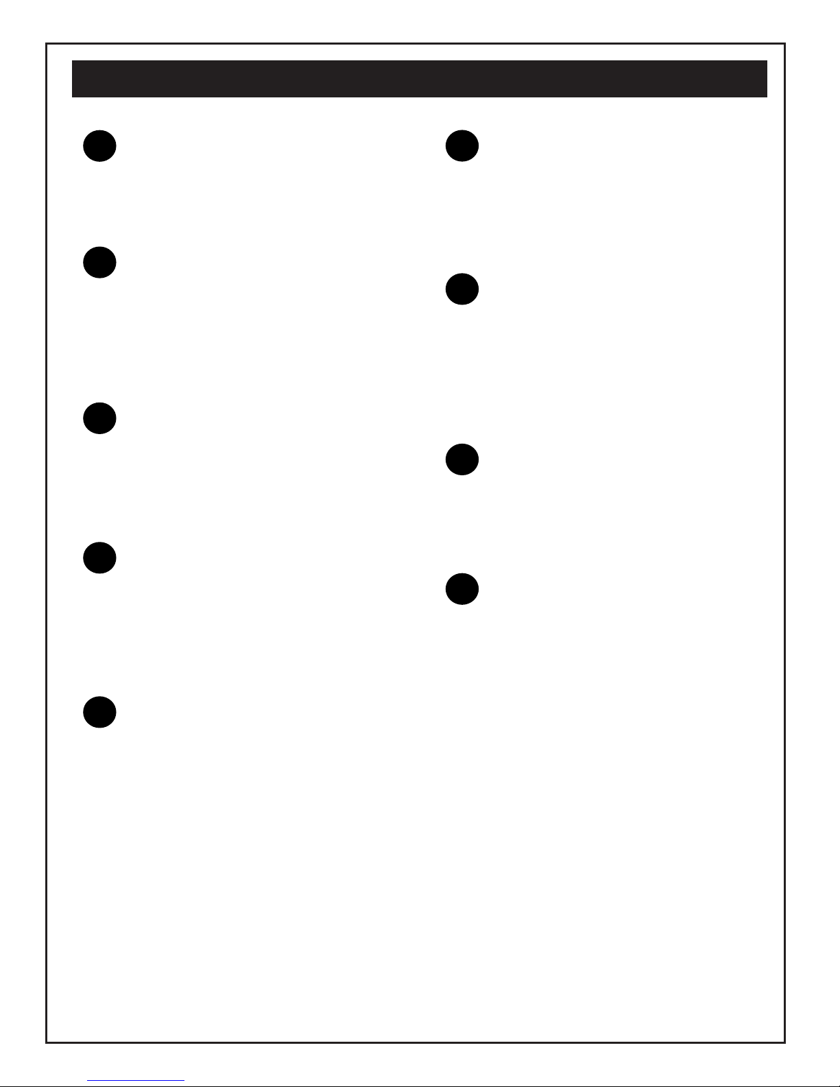
1FAN AND LIMIT CONTROL
The fan limit control turns the fan on
and off. It works off of temperature
and also provides a high temperature
safety limit.
2
3
4
5
6
7
8
9
SECONDARY HEAT EXCHANGER
More heat exchanger surface means
less heat up the Chimney. Made of 10
gauge steel rectangular tubes, which
the heat produced by the furnace,
passes through, before entering the
chimney.
EASY ACCESS CLEAN OUTS
The two clean out plates on the front
of the furnace allow easy access to
clean the Secondary Heat Exchanger
tubes. Keeping the inside of your fur-
nace clean insures high efficiency and
helps prevent creosote fires.
PICTURE FRAME FRONT
The front and back of the furnace is
built of 10 gauge steel and painted
with high temperature black paint. The
22 gauge painted side panels are de-
signed to slide onto the flanged steel
for easy installation.
LARGE LOADING FIRE DOOR
WITH POSITIVE DOOR LOCK
This 13” x 13” opening allows for easy
loading and larger diameter split logs.
The positive door lock ensures that
smoke and heat will not escape from
the furnace.
The round cast iron spinner disc
allows secondary air over the flame. It
helps burn smoke and unburned
gases that leave the flame, thereby
increasing efficiency.
FORCED DRAFT INDUCER
BLOWER
This furnace operates on a forced
draft principle. When the thermostat is
calling for heat, the draft blower will
turn on to get the fire burning. Draft
blower air disc must be open.
HONEYWELL TRANSFORMER /
RELAY
These Honeywell Transformers are the
industry standard and made for heating
systems. This 24V control circuit step-
down transformer is designed to power
any 24V control system, including ther-
mostats and relays.
EASY ACCESS ASH PAN
Designed to allow for easy removal of
ashes. Pulls out of furnace, equipped
with additional cross bar handle for
easy ash disposal.
HIGH TEMPERATURE FIREBRICK
1-1/4 thick Hi-Temperature firebrick
surrounds the wood/coal fire. The
Super Jack features 90 pounds of fire-
brick. This firebrick not only protects
the steel from the extreme combustion
temperature in the firebox, but it also
retains a substantial amount of heat
after the wood/coal fire burns down.
HEAVY CAST IRON GRATE
It is imperative that 80 percent of the
air for combustion enter the firebox
from below a wood/coal grate to insure
an efficient and clean burning fire. This
grate is made of heavy cast iron that
can endure the temperatures of wood
and coal fires.
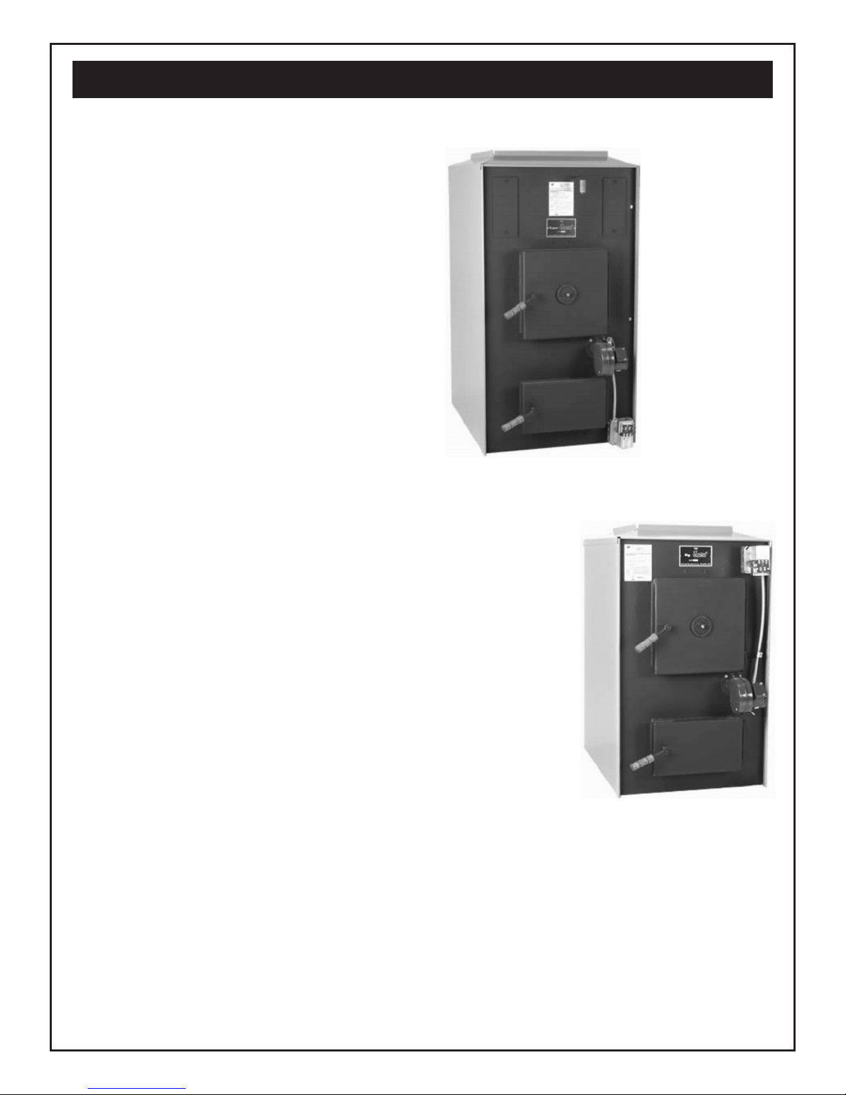
Furnace Features - SJ125
10