manuals.online logo
Brands
  1. Home
  2. •
  3. Brands
  4. •
  5. Jackson Systems
  6. •
  7. Thermostat
  8. •
  9. Jackson Systems Web Comfort Z-2000 Installation manual

Jackson Systems Web Comfort Z-2000 Installation manual

1 2 3
4 5 6
7
8 9
Quick Installation and Startup Guide
Insert a small coin
(dime) in the release
slot located on the
bottom of the
thermostat and gently
twist the coin to
release the thermostat
from the subbase.
Before mounting
the thermostat
subbase to the
wall, pull the
wires from the
HVAC unit
through the wire
access hole.
Mount and level
the subbase
using the
furnished
hardware.
After all wiring is landed, attached the thermostat to the subbase and apply 24 Volt power.
Land the remaining HVAC wires to the thermostat terminals based on the specific equipment configuration. If an indoor or outdoor remote sensor is used, wire the sensor to the T T terminals.
The sensor wiring must be a separate 18-2 cable and should not exceed 200’ in length from the sensor to the thermostat.
Refer to the thermostat Installation Manual for Advanced Installer settings that might be
required for the specific equipment applications as well as confirming that the baud rate is
set at 19.2 and the Modbus address is set at 01.
To simplify installation,
the transceiver comes
pre-wired to the
thermostat terminals with
leads for the HVAC unit
24 Volt hot and common.
Use wire connectors to
secure each lead to the
HVAC unit 24V ‘R’ and
24V ‘C’ wires. Land the
remaining HVAC unit
wires to their proper
terminals. Dress all wires
so that they do not come
in contact with the
thermostat PC board.
Set the system slide switches to match the
HVAC equipment application:
* For heat pump systems that energize the reversing valve on a call for heating (B), turn switch 4 ON.
SWITCH 6 MUST BE OFF AND SWITCH 8 MUST BE ON
Use the provided
6 transceiver log
to document the
serial number
located below the
bar code on the
back of the
thermostat
subbase. Also
note the
thermostat
location.
Turn the two
Modbus
configuration
slide switches
to ON.
. . . . . .
1 2 3 4 5 6 7 8
ON
. . . . . .
1 2
ON
. . . . . .
1 2 3 4 5 6 7 8
ON
. . . . . .
1 2
ON
SLIDE SWITCH SETTINGHVAC SYSTEM
6=1 HEAT / 1 COOL 8=5=ON4=OFF3=OFF2=OFF1=OFF 7=OFF
2 HEAT / 2 COOL 6=5=ON3=ON2=OFF1=OFF 4=OFF 8=7=OFF
6= 8=1=OFF 2=ON 3=OFF 4=OFF 5=ON 7=OFF
2 HEAT / 1 COOL
HEAT PUMP (O)*
6= 8=4=OFF 4=ON3=ON2=ON1=OFF 7=OFF
OFF ON
OFF ON
3 HEAT / 2 COOL
HEAT PUMP (O)*
OFF ON
OFF ON
W2
G3
Y2
G2
W1
O/B Y1 G1 R B A24 24C T
T
REV
VALVE
FAN 1
RELAY
TRANSCEIVER
THERMOSTAT
OPTIONAL
SENSOR
LINE
COMP 1
AUX
RELAY
HEAT
24 V
W2
G3
Y2
G2
W1
O/B Y1 G1 R B24C24 A T
T
REV
VALVE
FAN 1
RELAY
TRANSCEIVER
THERMOSTAT
OPTIONAL
SENSOR
LINE
COMP 1
RELAY
COMP 2
AUX
RELAY
HEAT
24 V
W2
G3
Y2
G2
W1
O/B Y1 G1 R B24 24C A TT
HEAT 1
RELAY
FAN 1
RELAY
TRANSCEIVER
THERMOSTAT
OPTIONAL
SENSOR
LINE
COMP 1
RELAY
COMP 2
RELAY
HEAT 2
RELAY
24 V
Multi-Stage Heat / CoolSingle Stage Heat / Cool 3 Heat / 2 Cool Heat Pump or Dual Fuel2 Heat / 1 Cool Heat Pump or Dual Fuel
LAND HVAC
UNIT WIRES
TO APPROPRIATE
TERMINALS
W2 Y2 W1 Y1 G R
O/B
24 24C B A T T
CR
The HVAC 24 Volt power must be OFF during wiring!
MN:1000140 R:100
SN: AU111400000
BACK OF SUBBASE
MOUNTING
TRANSCEIVER
(Push in on sides to release cover)
HOLES
FRONT OF SUBBASE
W2
G3
Y2
G2
W1
O/B Y1 G1 R B24 24C A T
T
HEAT
RELAY
FAN 1
RELAY
TRANSCEIVER
THERMOSTAT
OPTIONAL
SENSOR
LINE
COMP 1
RELAY 24 V
The serial number is
located on the inside
cover of the Energy
Manager. Document the
serial number as this
will be required when
provisioning the system.
10 11
13
15
12
14
06-1122-092920
Quick Installation and Startup Guide
.
5418 Elmwood Avenue, Indianapolis, IN 46203-6025
Toll Free: 888.652.9663 Fax: 317.227.1034
www.jacksonsystems.com
.
The Energy Manager should be mounted
near an Ethernet port which may be
located on a wall or at the router. The
Energy Manager also needs to be
plugged into a 120 Volt 50/60 Hz outlet.
After removing the cover, position and secure the antenna using the conduit nut attached to the antenna wire.
Make sure that the antenna is positioned as shown in the illustration. Mount the Energy Manager on a vertical
surface that is close to both the 120 VAC outlet and Ethernet ports and replace the cover.
Plug the power cord into a 120 VAC outlet.
Before plugging in the Ethernet cable,
confirm that the ports are live.
2. Click Launch. The username is admin The password is password
3. If the word Error is displayed under Status, internet communications is not connected.
Revisit 13 of the Installation Guide
4. Change default password
5. Refer to 5.4.2 in user manual to start adding thermostats
COMMUNICATIONS CONFIRMATION
1. Communications is confirmed if under Status the word Active is displayed.
Launch will also be displayed under Live Link.
PRE-STARTUP CHECKLIST
1. Power up all thermostats.
2. Power up the Energy Manager.
3. Confirm that Energy Manager to plugged
into a live internet port.
4. If a firewall is blocking the Energy Manager
from communicating to the internet, make sure
the following ports are open. These ports need
to be open for communication. These are UDP
ports and they are outbound.
a. 54260
b. 59368
c. 59369
An IT professional may be required to open ports.
TESTING THE ENERGY MANAGER INTERNET CONNECTION
1. Go to www.mywebcomfort.net
2. In the “Log” box, enter the following:
a. the serial number which is located under the inside cover
(Mac address) of the Energy Manager
b. “admin” for password
3. Click “Log in”.
4. If asked to change your user name, click “Remind me later”
Dashboard Settings
Display Information from:
to:
Welcome, (Customer Name) Viewer (Limited)
12/01/201211/01/2012
Status Alerts Premise Address kWh $/kWh SqFt Live Link
ShowHide Indicators ShowHide Columns
Active 0 0Location Address 0.00 0Customer Location Launch
Details
*+
Register New Manager

Other Jackson Systems Thermostat manuals
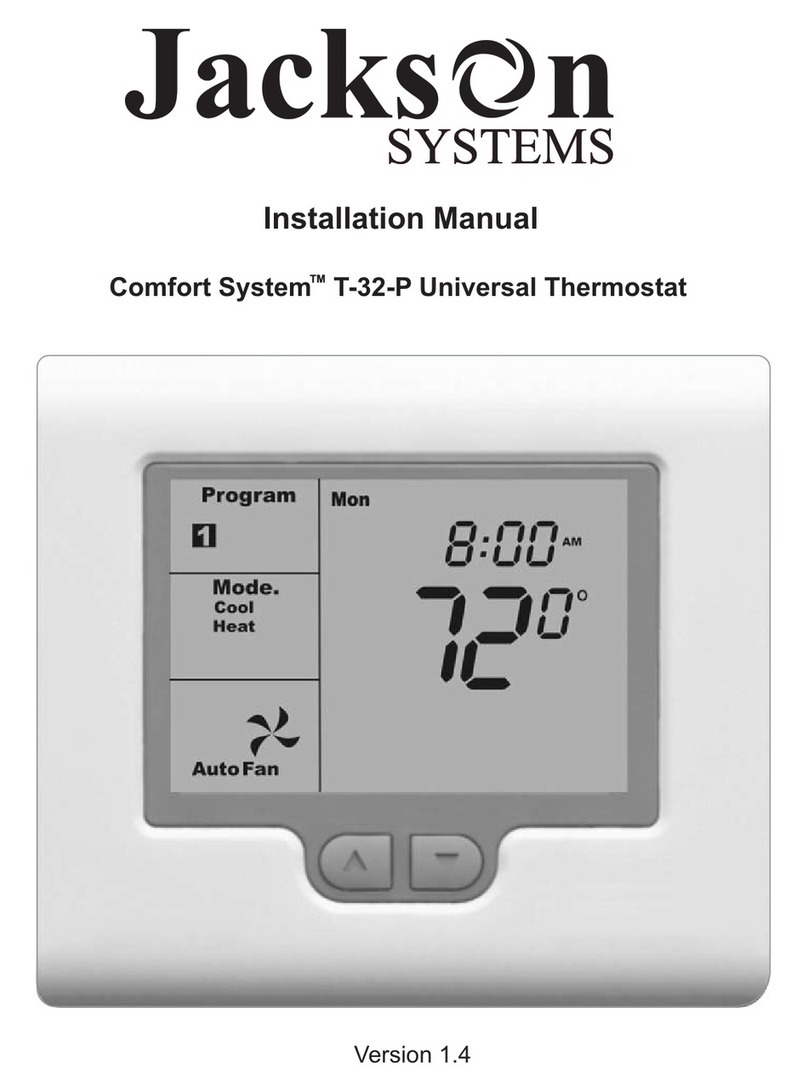
Jackson Systems T-32-TS Touchscreen Thermostat User manual

Jackson Systems

Jackson Systems T-32-TS Touchscreen Thermostat User manual

Jackson Systems T-32-TS Touchscreen Thermostat User manual

Jackson Systems

Jackson Systems T-32-TS Touchscreen Thermostat User manual

Jackson Systems COMFORT SYSTEM Z-2000-T User manual

Jackson Systems

Jackson Systems COMFORT SYSTEM Z-2000-T User manual

Jackson Systems Limit Stat LSL-HCB User manual

Jackson Systems

Jackson Systems Limit Stat LSL-HCB User manual

Jackson Systems Comfort System T-32-P User manual

Jackson Systems

Jackson Systems Comfort System T-32-P User manual

Jackson Systems Limit STAT User manual

Jackson Systems

Jackson Systems Limit STAT User manual

Jackson Systems Comfort System T-32-P User manual

Jackson Systems

Jackson Systems Comfort System T-32-P User manual

Jackson Systems Wireless Comfort WCT-32 User manual

Jackson Systems

Jackson Systems Wireless Comfort WCT-32 User manual

Jackson Systems WCT-32 User manual

Jackson Systems

Jackson Systems WCT-32 User manual

Jackson Systems Comfort System T-21-P User manual

Jackson Systems

Jackson Systems Comfort System T-21-P User manual

Jackson Systems Wireless Comfort WCT-32 User manual

Jackson Systems

Jackson Systems Wireless Comfort WCT-32 User manual

Jackson Systems WZ1 User manual

Jackson Systems

Jackson Systems WZ1 User manual

Jackson Systems Limit-Stat LS-HC User manual

Jackson Systems

Jackson Systems Limit-Stat LS-HC User manual

Jackson Systems Wireless Comfort WCZ-600-T User manual

Jackson Systems

Jackson Systems Wireless Comfort WCZ-600-T User manual

Jackson Systems T-32-TS Touchscreen Thermostat User manual
Jackson Systems

Jackson Systems T-32-TS Touchscreen Thermostat User manual

Jackson Systems Comfort System T-32-P User manual

Jackson Systems

Jackson Systems Comfort System T-32-P User manual

Jackson Systems Wireless Comfort WCT-32 User manual

Jackson Systems

Jackson Systems Wireless Comfort WCT-32 User manual
Popular Thermostat manuals by other brands

Bryant T6-PRH-A    li Installation instructions & replacement parts list

Bryant

Bryant T6-PRH-A li Installation instructions & replacement parts list

Carrier A07048 installation instructions

Carrier

Carrier A07048 installation instructions

nilan CTS 700 operating instructions

nilan

nilan CTS 700 operating instructions

Smeco CoolSentry Quick reference guide

Smeco

Smeco CoolSentry Quick reference guide

York Thermostat User's and service guide

York

York Thermostat User's and service guide

POLA HP43 Handbook

POLA

POLA HP43 Handbook

DeDietrich AD254 Installation, user and service manual

DeDietrich

DeDietrich AD254 Installation, user and service manual

Honeywell TH8320ZW1000 operating manual

Honeywell

Honeywell TH8320ZW1000 operating manual

Hunter 40020 installation instructions

Hunter

Hunter 40020 installation instructions

Carrier A07051 installation instructions

Carrier

Carrier A07051 installation instructions

ICM Controls SC1600L/VL manual

ICM Controls

ICM Controls SC1600L/VL manual

Remotec ZTS-110 Z-Thermostat user guide

Remotec

Remotec ZTS-110 Z-Thermostat user guide

HTS System AG TT-IR user manual

HTS System AG

HTS System AG TT-IR user manual

Moehlenhoff RD 40203 user manual

Moehlenhoff

Moehlenhoff RD 40203 user manual

GeneralAire GFX50 user manual

GeneralAire

GeneralAire GFX50 user manual

Heatstore HSUFCDC Installation and operating instructions

Heatstore

Heatstore HSUFCDC Installation and operating instructions

Hive Home Active Thermostat install guide

Hive Home

Hive Home Active Thermostat install guide

Multitek RF Room Thermostat user manual

Multitek

Multitek RF Room Thermostat user manual

manuals.online logo
manuals.online logoBrands
  • About & Mission
  • Contact us
  • Privacy Policy
  • Terms and Conditions

Copyright 2025 Manuals.Online. All Rights Reserved.