manuals.online logo
Brands
  1. Home
  2. •
  3. Brands
  4. •
  5. Jackson Systems
  6. •
  7. Thermostat
  8. •
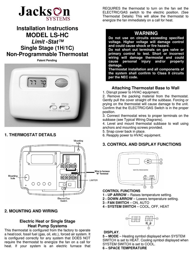
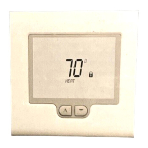
  9. Jackson Systems Limit STAT User manual

Jackson Systems Limit STAT User manual

Installation Manual
Model
LSL-HOB
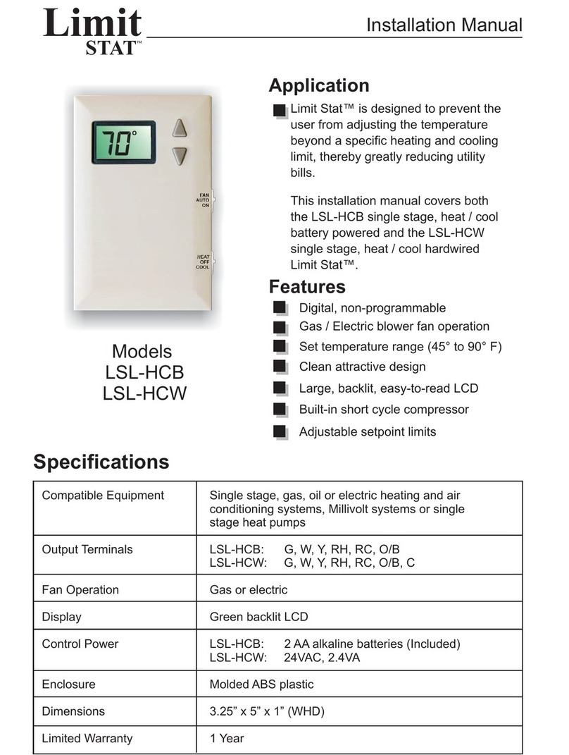
Limit Stat™ is designed to prevent the
user from adjusting the temperature
beyond a specific heating limit, thereby
greatly reducing utility bills.
This installation manual covers the
LSL-HOB single stage, heat only, battery
powered Limit Stat™.
Digital, non-programmable
Battery powered only
Large illuminated display
Clean attractive design
Application
Features
Compatible Equipment
Output Terminals
Fan Operation
Display
Control Power
Enclosure
Dimensions
Limited Warranty
24 Volt heating only systems, single stage gas or oil
systems, 2-wire hydronic heating systems (hot water,
baseboard or radiator) and Millivolt systems
RH, W1
Not used
Green backlit LCD
2 AA alkaline batteries (Included)
Molded ABS plastic
3.25” x 5” x 1” (WHD)
1 Year
Limit
STATTM
Specifications
O
Soft touch buttons
Easy installation
Adjustable heating setpoint limit
When using the LSL-HOB battery powered
Limit Stat™, the batteries must be removed
before changing any jumper settings. Wait at
least two minutes after removing the batteries
before changing a jumper or the change will
not be recognized by the thermostat.
JUMPER TABLE UP DOWN
JP1 System Furnace Heat Pump
JP2 Display Fahrenheit Celsius
JP3 Fan Gas Electric
JP4 Rev Valve O B
JP1 - System
This setting is not used on the LSL-HOB.
JP2 - Fahrenheit or Celsius Display
This jumper is used to select degrees F or C
which will be displayed on the LCD.
JP3 - Gas or Electric
This setting is not used on the LSL-HOB.
JP4 - Reversing Valve
This setting is not used on the LSL-HOB
Completing Installation
Thermostat Location
Turn off power to HVAC system.The Limit
Stat™ should be installed in a location that
represents the ambient space temperature.
Do not install the thermostat in an area where
drafts are present, near the floor, behind
doors or on an external wall. Avoid placing the
thermostat in areas where the air movement
is limited, affected by direct sunlight or other
areas not typical of the temperature in the
space.
1
Mounting the Subbase
When mounting the subbase, be aware that
drafts may travel down wall cavities and enter
the back of the thermostat through the control
wire hole in the wall. It is important to seal the
hole to prevent any drafts that might affect the
internal temperature sensor.
Pull the control wires through the large
opening in the thermostat subbase then level
and mount the subbase on the wall using the
supplied anchors and screws. Do not over
tighten the mounting screws as the
subbase may warp causing improper
seating of the thermostat connecting pins
to the terminal block.
2
Limit Stat™
G
W1
W2
Y2
Y1
RH
RC
B/O
Use a properly sized screwdriver and land
each wire to its dedicated terminal as
illustrated in Section 4. Do not over tighten
the terminal screws.
Check to ensure that all wires are landed
correctly and dressed properly to prevent any
shorts.
3
Setup Options
.
.
.
.
.
.
4
Once all optional jumper settings have been
made, replace the batteries. Install the
thermostat on its subbase with the bottom tilted
out. Line up the two holes at the top with the two
hooks on the subbase. Slowly pivot the bottom
of the thermostat towards the subbase and push
firmly until it is securely latched.
Do not attempt to force the two halves
together.
Remove the plastic film (if present) that is
protecting the LCD display.
Turn power back on to HVAC system.
Mode Switch
The MODE switch has three positions: HEAT
and OFF. Set the MODE switch to HEAT to
control the heating system. When the MODE
switch is set to OFF, no heating or cooling will
take place.
Fan Switch
The FAN switch is not used on the LSL-HCW.
Temperature Change Buttons
When the Limit Stat™ is in the HEAT mode, a
single press on either the UP or DOWN button
will cause the LCD to display the word SET.
Once SET is displayed, the setpoint value will
start flashing. The setpoint can now be
changed by pressing or holding the UP or
DOWN button. Pressing the UP or DOWN
button will also illuminate the display for
easier viewing in dim light conditions. The
light will remain on for approximately 12
seconds.
Under normal use, the Limit Stat™ requires
no special maintenance. The LSL-HOB,
battery powered model requires that the
batteries be replaced at least once per year or
whenever the “LO BAT” symbol appears on
the LCD.
To replace the batteries, release the
thermostat from the subbase by pressing the
thumb latch located at the bottom of the unit
and swinging the thermostat up and away
from the subbase. Remove the used batteries
from the battery tray and discard
appropriately.
System Switch
5
6
Maintenance
Install two new AA Alkaline batteries into the
battery tray. Match the battery direction with the
polarity markings on the battery compartment
to ensure proper operation. When finished,
replace the thermostat on the subbase by
lining up the two holes in the top of the
thermostat with the two hooks on the top of the
subbase. Slowly pivot the bottom of the
thermostat towards the subbase and push
firmly until the thermostat is securely latched to
the subbase. Do not attempt to force the two
halves together.
This thermostat must be wired in accordance
with all applicable local codes and ordinances.
The thermostat should be limited to a
maximum of 1.5 amps. Higher current may
cause damage to the thermostat.
This installation manual should not be left
with unauthorized users as it contains
installer setup functions which, if not
correctly set, may cause damage to the HVAC
equipment or seriously affect performance.
The Limit Stat™ thermostat is intuitive, reliable
and easy to install. Using a common sense
approach to the installation will ensure this
product is installed properly and to the customer’s
satisfaction. Please take time to read and
understand this manual so that installation and
testing is undertaken in an efficient manner.
Although great care has been taken in
preparation of this manual, Jackson Systems
takes no responsibility for errors or
omissions contained herein. It is the
responsibility of the installer to ensure that
this thermostat and the equipment connected
to it operate in a safe and efficient manner.
Due to ongoing product improvements, Jackson
Systems reserves the right to change the
specifications of the Limit Stat™ thermostat or its
components without notice.
All rights reserved.
© Jackson Systems, LLC 2010
Intellectual rights apply.
7
Important Installation Notes
5418 Elmwood Avenue, Indianapolis, IN 46203-6025
Toll Free: 888.652.9663 Fax: 317.227.1034
www.jacksonsystems.com
06-1071-062011
Setting the Heating Limit
This manual is to be used by the installer only and contains
information on setting the heating setpoint limit. Avoid leaving this
installation manual with anyone who could compromise the settings.
To set the Heating setpoint limit, place the MODE switch in the OFF
position. Press and hold the UP button while sliding the MODE switch to
Heat. The LCD will display “Ht LIM”. Adjust the maximum heating setpoint
by using the UP and DOWN buttons.
NOTE: If no buttons are pressed for 4 seconds, the thermostat will accept
the limit value that is displayed on the LCD and return to normal operation.
Once the heating setpoint limit is adjusted and the thermostat returns to
normal operation, confirm that the setpoint can not be raised above the
limit and then allow the thermostat to return to normal operation.

This manual suits for next models

1

Other Jackson Systems Thermostat manuals

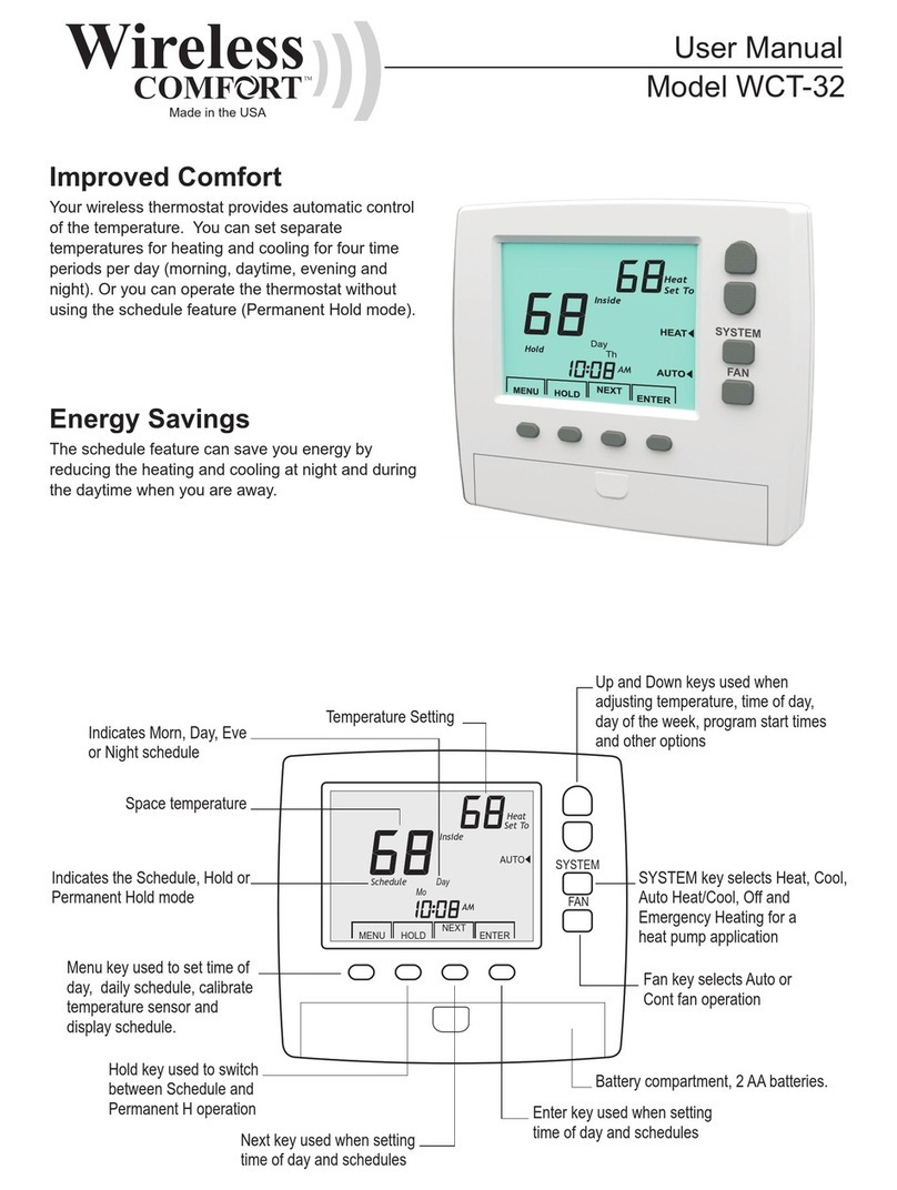
Jackson Systems Wireless Comfort WCT-32 User manual

Jackson Systems

Jackson Systems Wireless Comfort WCT-32 User manual

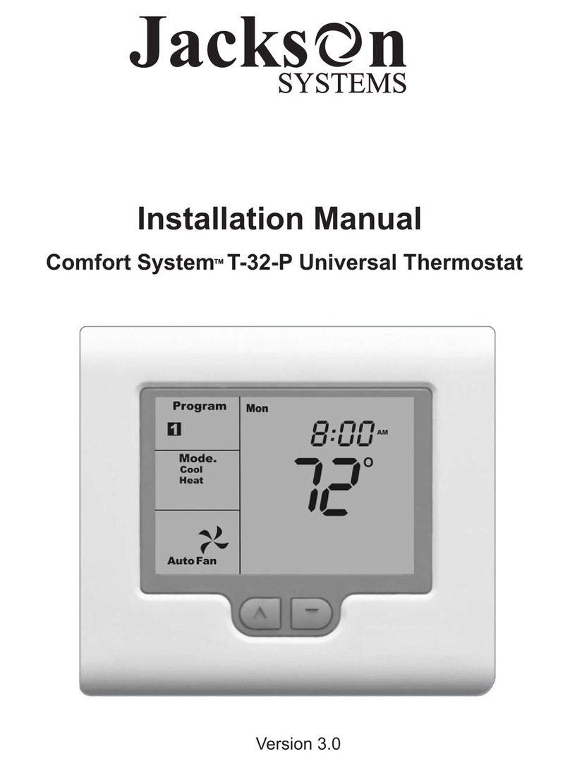
Jackson Systems Comfort System T-32-P User manual

Jackson Systems

Jackson Systems Comfort System T-32-P User manual

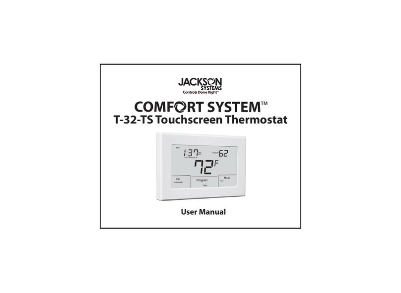
Jackson Systems T-32-TS Touchscreen Thermostat User manual

Jackson Systems

Jackson Systems T-32-TS Touchscreen Thermostat User manual

Jackson Systems Limit Stat LSL-HCB User manual

Jackson Systems

Jackson Systems Limit Stat LSL-HCB User manual

Jackson Systems T-32-TS Touchscreen Thermostat User manual

Jackson Systems

Jackson Systems T-32-TS Touchscreen Thermostat User manual

Jackson Systems Wireless Comfort WCT-32 User manual

Jackson Systems

Jackson Systems Wireless Comfort WCT-32 User manual

Jackson Systems WZ1 User manual

Jackson Systems

Jackson Systems WZ1 User manual

Jackson Systems T-32-TS Touchscreen Thermostat User manual

Jackson Systems

Jackson Systems T-32-TS Touchscreen Thermostat User manual

Jackson Systems WCT-32 User manual

Jackson Systems

Jackson Systems WCT-32 User manual

Jackson Systems Limit-Stat LS-HC User manual

Jackson Systems

Jackson Systems Limit-Stat LS-HC User manual

Jackson Systems COMFORT SYSTEM Z-2000-T User manual

Jackson Systems

Jackson Systems COMFORT SYSTEM Z-2000-T User manual

Jackson Systems Wireless Comfort WCZ-600-T User manual

Jackson Systems

Jackson Systems Wireless Comfort WCZ-600-T User manual

Jackson Systems Comfort System T-32-P User manual

Jackson Systems

Jackson Systems Comfort System T-32-P User manual

Jackson Systems Comfort System T-21-P User manual

Jackson Systems

Jackson Systems Comfort System T-21-P User manual

Jackson Systems Web Comfort Z-2000 Installation manual

Jackson Systems

Jackson Systems Web Comfort Z-2000 Installation manual

Jackson Systems Wireless Comfort WCT-32 User manual

Jackson Systems

Jackson Systems Wireless Comfort WCT-32 User manual

Jackson Systems Comfort System T-32-P User manual

Jackson Systems

Jackson Systems Comfort System T-32-P User manual

Popular Thermostat manuals by other brands

Lux Products PH521 Installation and operating instructions

Lux Products

Lux Products PH521 Installation and operating instructions

Lux Products LUX/GEO quick start guide

Lux Products

Lux Products LUX/GEO quick start guide

Micro control systems MCS-THERMOSTAT Installation and reference guide

Micro control systems

Micro control systems MCS-THERMOSTAT Installation and reference guide

Reznor EGHB Series Instructions & installation

Reznor

Reznor EGHB Series Instructions & installation

Full Gauge RT-607Ri plus manual

Full Gauge

Full Gauge RT-607Ri plus manual

Honeywell XE70 SERIES Product data

Honeywell

Honeywell XE70 SERIES Product data

Honeywell T827B installation instructions

Honeywell

Honeywell T827B installation instructions

DEVI DEVIreg Touch user guide

DEVI

DEVI DEVIreg Touch user guide

Daikin BACnet IM 1234-1 Installation and maintenance manual

Daikin

Daikin BACnet IM 1234-1 Installation and maintenance manual

Magnum Heating MAGNUM Foil installation manual

Magnum Heating

Magnum Heating MAGNUM Foil installation manual

Tempro TP500 operating instructions

Tempro

Tempro TP500 operating instructions

Uponor T-27 Installation and operation manual

Uponor

Uponor T-27 Installation and operation manual

EPH Controls RDT Installation and operation guide

EPH Controls

EPH Controls RDT Installation and operation guide

JAROLIFT TDRRT-01W Original instructions

JAROLIFT

JAROLIFT TDRRT-01W Original instructions

Tekmar tekmarNet2 Thermostat 530 Installation & operation manual

Tekmar

Tekmar tekmarNet2 Thermostat 530 Installation & operation manual

Leviton 6327-1 instruction manual

Leviton

Leviton 6327-1 instruction manual

Regin MTIBL90H instructions

Regin

Regin MTIBL90H instructions

meitav-tec ETN24-P-3S-HU owner's manual

meitav-tec

meitav-tec ETN24-P-3S-HU owner's manual

manuals.online logo
manuals.online logoBrands
  • About & Mission
  • Contact us
  • Privacy Policy
  • Terms and Conditions

Copyright 2025 Manuals.Online. All Rights Reserved.