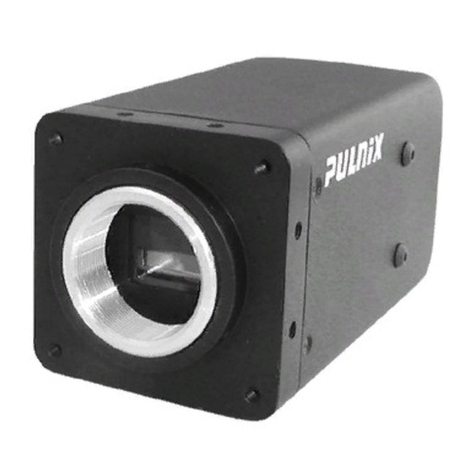
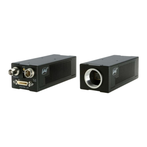
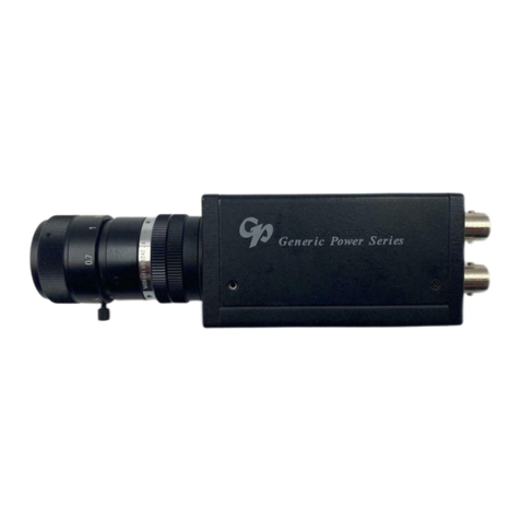
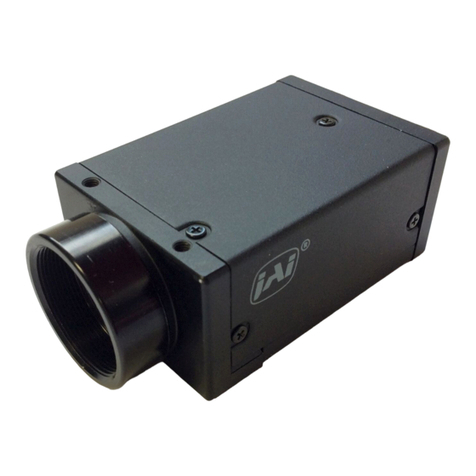
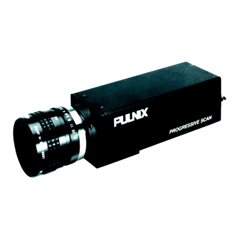
JAI CV-M10 User manual

Operation Manual
Progressive Scan Camera
(Rev.F)
CV-M10

CV-M10BX/CV-M10RS
DECLARATION OF CONFORMITY
ASDEFINEDBYTHECOUNCILDIRECTIVE
89/336/EEC
EMC (ELECTROMAGNETIC COMPATIBILITY)
WE HEREWITH DECLARE THATTHIS PRODUCT
COMPLIES WITHTHE FOLLOWING PROVISIONS APPLYING TO IT.
EN-50081-1
EN-50082-1

CV-M10BX/CV-M10RS
Table of Contents
1. General .............................................................................................................................................................................. 1
2. Standard Composition....................................................................................................................................................... 1
3. Main Features ................................................................................................................................................................... 1
4. Locations and Functions .................................................................................................................................................. 2
5. Pin Assignment................................................................................................................................................................. 3
5.1. 12-pin Multi-connector (DC-IN/SYNC.) ........................................................................................................................ 3
5.2. 6-pin Multi-connector (RS 232C/TRIGGER)................................................................................................................. 3
6. Functions and Operation.................................................................................................................................................. 4
6.1. Input/Output of HD/VD Signal.................................................................................................................................... 4
6.1.1. Input of External HD/VD signals ......................................................................................................................... 4
6.1.2. Output of Internal HD/VD signals ...................................................................................................................... 4
6.2. Continuous operation ................................................................................................................................................ 4
6.3. External Trigger Mode ................................................................................................................................................ 5
6.3.1. Edge Pre-select Trigger Mode ............................................................................................................................ 5
6.3.2. PulseWidth Control Trigger Mode ..................................................................................................................... 5
6.4. Timing diagram for Edge Pre-select........................................................................................................................... 6
6.5. Timing diagram for Pulse Width Control..................................................................................................................... 7
7. Mode Settings .................................................................................................................................................................. 8
7.1. Mode Setting by Switch .............................................................................................................................................. 8
7.1.1. M10BX Internal Switch SW1 Settings (On PK8206) ............................................................................................. 8
7.1.2. M10BX Switch SW1 Settings (On rear panel)...................................................................................................... 8
7.1.3. M10RS Switch SW1 Settings (On rear panel) ...................................................................................................... 8
7.2. Shutter Time select .................................................................................................................................................... 9
7.2.1. CV-M10BX SW1 on PK8206 ................................................................................................................................. 9
7.2.2. SW1-1 to SW1-3 on rear...................................................................................................................................... 9
7.3. Trigger select.............................................................................................................................................................. 9
7.3.1. Normal Shutter mode ......................................................................................................................................... 9
7.3.2. Ext. Trigger mode ............................................................................................................................................... 9
7.4. Scanning Mode .......................................................................................................................................................... 9
7.4.1 Interlaced mode.................................................................................................................................................. 9
7.4.2. Non interlaced mode ........................................................................................................................................ 10
7.5. Gamma Correction .................................................................................................................................................... 10
7.6. Gain Control/RS 232C control ................................................................................................................................... 10
7.6.1. Gain control on CV-M10 ..................................................................................................................................... 10
7.7. CV-M10RS Serial Interface for Controls...................................................................................................................... 10
7.7.1. RS232C Cable Connect...................................................................................................................................... 10
8. Jumper settings ................................................................................................................................................................11
8.1. HD/VD signals ............................................................................................................................................................11
8.2. Trigger input termination............................................................................................................................................11
8.3. Trigger mode selection...............................................................................................................................................11
8.4. Pixel clock or video 2 on pin 9 (12 pin con.) ...............................................................................................................11
8.5. Alternative input/outputs on pin #6 and #7 (12 pin con.) ..........................................................................................11
8.6. Locations of Jumper .................................................................................................................................................. 12
8.6.1. Location of Jumper on PK8189A ........................................................................................................................ 12
8.6.2. Location of Jumper on PK8187A ....................................................................................................................... 12
8.6.3. Location of Jumper for CV-M10BX on PK8206A ................................................................................................. 13
8.6.4. Location of Jumper for CV-M10RS on PK8190A.................................................................................................. 13
9. Internal adjustments on BX............................................................................................................................................. 14
9.1. Potentiometer locations on PK8206A........................................................................................................................ 14
10. CV-M10RS Camera Control Tool ...................................................................................................................................... 15
10.1. Control Bar for CV-M10RS Camera Control ................................................................................................................ 15
10.2. About and Help Window .......................................................................................................................................... 15
10.3. Shutter Window ....................................................................................................................................................... 15
10.4. Gain Window ........................................................................................................................................................... 15
10.5. Levels Window ........................................................................................................................................................ 16
10.6. Files and Camera ..................................................................................................................................................... 16
10.7. Communication Window.......................................................................................................................................... 16
11. External Appearance and Dimensions ........................................................................................................................... 17
12. Specifications ................................................................................................................................................................ 18
12.1. Spectral sensitivity................................................................................................................................................... 18
13. Appendix........................................................................................................................................................................ 19
13.1. Precautions .............................................................................................................................................................. 19
13.2. Typical CCD Characteristics...................................................................................................................................... 19
13.3. References .............................................................................................................................................................. 19
14. Users Record................................................................................................................................................................. 20
15. Index ............................................................................................................................................................................. 20

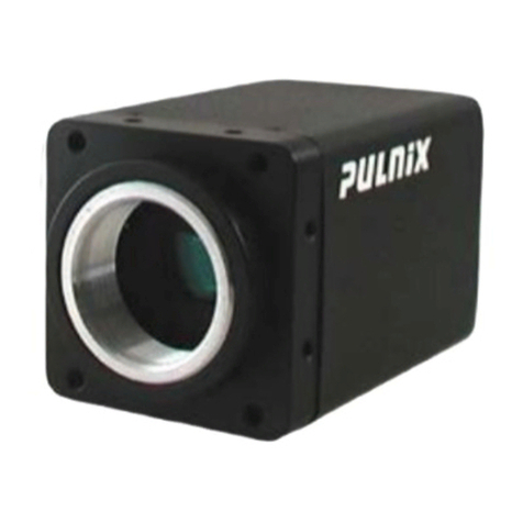
CV-M10BX/CV-M10RS
- 1 -
1. General
TheCV-M10is a compact monochrome progressivescan cameradesigned forautomated imaging applications.The1/2"
CCDwith square pixelsoffers asuperbimage quality.Thehigh-speed shutterfunctionand asynchronousrandom trigger
modeallows the camerato capturehigh quality imagesof fastmoving objects. Thedual tappedvideo output allowsthe
cameratooperatewitha highframerate.Thecameracan operate incontinuousmodeandwithtriggered edge pre-select
andpulsewidthcontrolledshutter.
2. Standard Composition
Thestandardcamera composition consistsofthe camera mainbody,tripod mounting plateandoperation manual.
CV-M10 is available inthefollowingversions:
ForEIA(VGAcorresponded).
CV-M10BXEis the basicprogressivescan camerawith all functions.
CV-M10RSEistheextendedversionwithdigitalset-upfunctionviaRS232Cserialcontrol.
ForCCIR.
CV-M10BXCisthebasic progressivescan camerawithallfunctions.
CV-M10RSCistheextendedversionwithdigitalset-upfunctionviaRS-232Cserialcontrol.
3. Main Features
* 1/2"monochromefullframe progressivescaninterlinetransferCCD
* 782(h)x 582(v)8.37µmsquarepixels(767 x580pixelsread out)forCCIR
* 659(h) x 494(v) 9.9µmsquarepixels (748 x492 pixels readout) for EIA
* EIAversioncorrespondstotheVGAformat
* Highspeedshutterupto 1/800,000 sec.forEIAand1/917,000sec. for CCIR
* Singlechannel progressivefullframe readout in1/25 sec. or1/30 sec.
* Dualchannel progressivefull frame readout in1/50 sec.or 1/60 sec.
* Interlacedornon-interlaced readout
* Longtimeintegration up to16fields
* Edgepre-select and pulsewidth controlledexternaltrigger modes
* Pixelclockoutputoptional
* CamerasetupviaRS-232C or switches
* Windows95/98/NTsetupsoftware

- 2 -
CV-M10BX/CV-M10RS
4. Locations and Functions
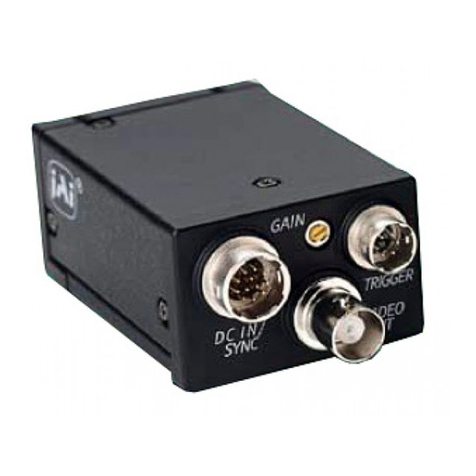
9
3 5 6
4 8 7
1
2
CV-M10BX
1. Lens mount of C-mount type. *1)
2. Interline-transfer CCDsensorwith on-chipmicro lenses.
3. Video output 1. VS 1.0 Vp-p. *2)
4. Video output 2. VS 1.0 Vp-p. (Only in 2 :1 interlaced mode.) *2)
5. SW1 switch on the rear panel to set the shutter speed and other function modes.
6. 6 pin connector for RS 232C signals, input of external trigger pulse and WEN output.
7. 12 pin connector for DC +12V power external sync signals and output of video 2
8. GAIN potmeter for adjusting level of video 1. (Min. gain is fully clockwise.)
9. Tripod mount plate to place the camera on tripod.
*1)Note: RearprotrusiononC-mountlensmustbelessthan10.0mm(0.4inchapprox.)
WhenIRcut filterisused,it mustbeless than 7.0mm(0.28 inchapprox.)
TheIR cutfilteris placedin theC-mountthread.
TheC-mount25 mmIRcut filtermustbe ordered separately.
*2)Note: In 2:1 interlace mode the 2 fields are read out simultaneously on video 1 and video 2. Each output is a normal
interlacedvideosignal,whichcanbemonitoredonanormalvideomonitor.Afullprogressivescannedframecan
beobtainedbycombining the2outputsina framegrabber.

CV-M10BX/CV-M10RS
- 3 -
5. Pin Assignment
5-1. 12-pin Multi-connector (DC-IN/SYNC.)
Type:HR10A-10R-12PB-01(Hirose)maleseenfromrear.
3
456
7
8
9
10
11 12
1
2
Notes: *1) Signals onpin no. 6,7and 9canbe changedbyjumper setting.
See"8.JumperSettings"formore information.
*2)InEdgePre-selectandPulse Width Controlmodedonotinputext.VD signal.
5.2. 6-pin Multi-connector (RS 232C/TRIGGER)
Type:HR10A-7R-6PB(Hirose)maleseenfromrear.
Note: WEN is generated in Normal Trig, RandomTrig (normal and high speed
shutter)andLowSpeedShutter.Itis1Hlongandindicatesthebeginning
ofvideoreadout.
Pin no. Signal Remarks
1
GND
2
+12 VDC input
3
GND
4
Video 1 output Parallel with the BNC video 1 output. Avoid double termination.
5
GND
6
HD input/output Ext. HD in as factory setting. *1)
7
VD input/output Ext. VD in as factory setting. *1) *2)
8
GND
9
Video 2 output Video 2 only in 2:1 interlace. Pixel clock output. Opt. *1)
10
GND
11
+12 V DC input
12
GND
Pin no. Signal Remarks
1
TXD out NC on BX version
2
RXD in NC on BX version
3
GND
4
NC
5
Ext. Trig input
6
WEN output * Note
1
234
5
6

- 4 -
CV-M10BX/CV-M10RS
6. Functions and Operation
Apartfrom thestandardcontinuous operation,theCV-M10features twoexternalasynchronous triggermodes, EdgePre-
selectandPulseWidthControlmode.These2externaltriggermodescanoperatewitheitherHresetorHnon-reset.InEdge
Pre-selectand H reset, the internalHD isreset on the falling edgeof thetrigger and the exposure starts.For PulseWidth
Control and H reset, the rising edge of the trigger will stop the exposure and reset the internal HD. In H non-reset, the
exposurewill be synchronizedto theinternalHD. Itwillstart onthefirst HDafter the triggernegative goingedge.
6-1. Input/Output of HD/VD Signal
6.1.1.Inputof External HD/VDsignals
This setting is factory pre-set. The video output is synchronized with external HD/VD signals if applied. If no ext. HD is
connected, the camera will switch to the internal X-tal controlled HD sync. If no ext. VD is connected, the camera will
continuewithitsinternal VD.
TheexternalHD/VDsignalshouldbe4.0Vp-p±2.0Vfroma75ohmsource.IncaseofTTLlevelinput2.0to5.0Vthe75ohm
terminationcanbe removedbyopenJP3/JP6 onPK8189Aboard.
6.1.2.Outputof InternalHD/VDsignals
Inorder tooutputinternal HD/VDsignal4.0Vp-p froma 75 ohmsource, ajumpersetting isrequired. JP1/JP4 onPK8189A
boardis tobe open,and JP5/JP7are tobe short.
6.2. Continuous operation
Forapplicationthatdonotrequireasynchronousexternaltrigger,butrunincontinuousoperation,thismodeisused.SW1-
4TriggerselectoncamerarearissettoONfornormalinternaltriggermode.Theshuttertimeorexposuretimeareselected
bySW1-1toSW1-3oncamerarear(andSW1-1toSW1-4onPK8206forBXversions).ThesettingcanbedoneviaRS232Cfor
theRSversions.
Theshutter timecan beselected within thefollowing range:
Normalshutter 8step.1/50to1/10,000sec.forCCIR.1/60to 1/10,000 sec. forEIA
Highspeedshutter 8step.1/25,000to1/917,000secforCCIR.
1/20,000sec.to1/800,000sec.forEIA
Lowspeedshutter 8 step. 2fieldsto 16fields forCCIRandEIA
EDGE PRE-SELECT
EDGE PRE-SELECT
H non-reset
EDGE PRE-SELECT
H reset
PULSE WIDTH
Trigger
Trigger
Trigger
int. HD
Trigger
int. HD
Read out
Exposure
shutter time
Read out
Exposure
shutter time
Read out
Exposure
Read out
Exposure
shutter time

CV-M10BX/CV-M10RS
- 5 -
2.0µs~1ms
4.0V(p p)
±1.0V
AA AA
Ext.Trigger
Ext.HD
A=4.4
µ
S
6.3. External Trigger Mode
Externaltriggermode ofCV-M10allows 2differentdrivingmodes:
1 EdgePre-select mode.(Asynchronousreset andexposurestart byan ext.trigger)
2 PulseWidthControlmode.(Exposure control bythelowperiodofthe ext. trigger)
For both there are two trigger modes. H reset and H non-reset. H non-reset mode allows input of synchronized external
triggerandexternalHD.
ThetriggerinputisACcoupled,sothereisamaximumpulsewidthforthetriggerpulseabout1msec.Thesignallevelmust
be4.0Vp-p+/-2.0Vontheinput,whichisnon-terminated.Thetriggerinputcanbechangedto75ohmbyshortingJP10.See
instructionsin"8.JumperSettings".
6.3.1. Edge Pre-selectTrigger Mode
Thistrigger mode canoperate inHreset modeorH non-resetmode.
InHresetmodethefallingedgeofthetriggerwillimmediatelyresettheinternalHDandstarttheexposure.Thetriggerinput
shouldbe>2µsec.to<1msec.Ifthecamerais synchronized toanexternalHD,therearesome requirements tothephase
betweentheext.HDand theExt.trigger.Thefallingedge of thetriggershouldbewithin4.4 msec.fromthefallingedgeof
theext.HD.Otherwise thejitterwillbetoo high. (Seefig.6.3)
InHnon-resetmodetheexposurewillstartatthefirstinternalHDafterthetrigger.Thetriggerinputshouldbe>64µsec.to
<1msec.Anexternaltriggerpulseinitiatesthecapture,andtheexposuretime(accumulationtime)isgovernedbythefixed
shutterspeed set up by therear panelDIP-switches, (internal switch for BXversion.) orvia RS-232C. The resulting video
signalwillstarttobereadoutaftertheselectedshuttertime.The WEN pulse indicatesthestartofvalidvideosignal.Refer
totiming chartsfordetails. Anew trigger pulsemust notbeapplied beforethe video readout hasbeenfinished.
Touse thismode
Set: SW1-4onBX rear toOFFfor random trigger.ForRS select triggermode.
JP12onPK8206 (BX ver.)orPK8190(RS ver.)OPENforEdgePre-select
JP13onPK8206(BXver.)or PK8190(RSver.)OPENforHReset
JP13onPK8206(BXver.)orPK8190(RSver.)ShortforHNonReset
SW1-1throughSW1-3on rearandSW1on(BX) PK8206 forexposuretime
Note: ForCV-M10RS theselectionofEdge Pre-select, PulseWidthControl H ResetandHnon-reset cannotbedoneby
RS232C.
(Seechapter 7and 8for details)
6.3.2. Pulse Width Control Trigger Mode
Thistrigger mode canoperate inHreset modeorH non-resetmode.
InHresetmodethe exposure willstartimmediatelyatthefallingedge ofthetrigger.(TheinternalHwill not bereset).The
exposurewill endand theinternal Hwill bereset at the rising edgeof thetrigger.
InH-non-resetmode thetriggerandHD issynchronized.Theexposure willstartatthe firstHDpulseafter thefallingedge
ofthetrigger.Theexposurestops atthetriggerrisingedge.Thetriggerpulsecanbeanythingbetween>1Hand<625H. To
avoidjitter,thecamerashould be synchronized toanexternalHD.There are somerequirementstothephasebetweenthe
ext.HDandtheExt.trigger.Thefallingandrisingedgeofthetriggershouldbewithin4.4µsec.fromthefallingedgeofthe
ext.HD.(Seefig.6.3)

- 6 -
CV-M10BX/CV-M10RS
Theresulting videosignal willstart tobe readout after the trigger rising edge. The WEN pulseindicates thestart ofvalid
videosignal.Referto timing chartsfordetails.
Anew triggerpulse mustnot be appliedbefore thevideo readout hasbeenfinished.
Touse thismode:
Set: SW1-4onBX reartoOFF for randomtrigger.For RSselecttrigger mode
JP12 onPK8206(BX ver.) orPK8190(RS ver.) ShortforPulse Width Control
JP13onPK8206(BX ver.)orPK8190(RS ver.) OPENforH Reset
JP13onPK8206(BX ver.) orPK8190(RSver.) Shortfor H Non Reset
SW1-1throughSW1-3onBXreartoON(1/10,000)ForRSselect1/10,000
andSW1on(BX)PK8206forNormalshutter.
Note: ForCV-M10RS theselectionofEdge Pre-select, PulseWidthControl H ResetandHnon-reset cannotbedoneby
RS232C. InPulseWidth ControlModetheshutter speedmustbe set at1/10000sec.
(Seechapter 7and 8for details)
6.4. Timing diagram for Edge Pre-select
TRIG
XSUB
XSG
WEN
VIDEO 1
VIDEO 2
VIDEO 1
2:1 interlace in field accumulation
Non interlace in frame accumulation
7HD EIA:247HD CCIR:291HD
14HD EIA:494HD CCIR:582HD
exposure time
Edge pre select mode (H reset)
HD RESET
INT HD
TRIG
EXT ED
XSUB
XSG
WEN
VIDEO 1
2:1 interlace in field accumulation
VIDEO 2
VIDEO 1
Non interlace in frame accumulation
7HD EIA:247HD CCIR:291HD
14HD EIA:494HD CCIR:582HD
Edge pre select mode (H Non Reset)
exposure time

CV-M10BX/CV-M10RS
- 7 -
6.5. Timing diagram for Pulse Width Control
1HD~625HD
EIA:247HD CCIR:291HD
EIA:494HD CCIR:582HD
HD RESET
7HD
14HD
TRIG
INT HD
XSUB
XSG
WEN
VIDEO 1
2:1 interlace in field accumulation
VIDEO 2
VIDEO 1
Non interlace in frame accumulation
Pulse width control mode (H Reset)
exposure time
TRIG
EXT ED
XSUB
XSG
WEN
VIDEO 1
2:1 interlace in field accumulation
VIDEO 2
VIDEO 1
Non interlace in frame accumulation
7HD EIA:247HD CCIR:291HD
14HD EIA:494HD CCIR:582HD
Pulse width control mode (H Non Reset)
1HD~625HD
exposure time

- 8 -
CV-M10BX/CV-M10RS
OFF ON
1
2
3
4
5
6
7
8
SCANNING
TRIGGER
Interl
.
<>
Non Interl.
Random trig
<>
Normal
SHUTTER
1
<>
0.45
GAMMA
<
<
<
shutter
High speed
shutter
<
<
>
<
>
<
<
>
>
>
<
<
>
<
>
>
>
<
>
>
>
1/60 1 /20000 2
1/125 1 /40000 4
1/250 1 /60000 6
1/500 1 /80000 8
1/1000 1 /100000 10
1/2000 1 /200000 12
1/4000 1 /400000 14
1/10000 1/800000 16
Normal
shutter
<
<
GAIN << >
<> <
Fixed
Rear
potm.
AGC
Low speed
7. Mode Settings
7.1. Mode Setting by Switch
ThemodesettingswitchSW1onrearforCV-M10BXandCV-M10RSisdifferentforswitchSW1-1toSW1-3andSW1-7toSW1-
8.For BXthe shutter values can beselected in3 rangesdepending of the internal SW1 on thePK 8206board. Theswitch
selectbetween Normal, Highspeed or Lowspeed. In thefollowing the switchsettings areshown.
7.1.1.M10BXInternalSwitchSW1Settings(OnPK8206)
7.1.2. M10BX Switch SW1 Settings (On rear panel)
Note:Theshownswitch settingsare thefactory setting. Valuesare shownforEIA.
OFF ON
1
2
3
4
<
<
<
<
<
<
>
<
>
<
>
<
<
<
<
>
<
<
>
>
<
<
Shutter off
Flickerless
Normal shutter
High speed shutter
Low speed shutter
RS232
Switch on rear
<>
R S232C
Switch on rear
<>
R S232C
OFF ON
1
2
3
4
5
6
8
SCANNING
TRIGGER
Interl.
<>
Non Interl.
Rando m trig
<>
Normal
SHUTTER
1
<>
0.45
GAMMA
<
<
<
<
<
>
<
>
<
<
>
>
>
<
<
>
<
>
>
>
<
>
>
>
1/60
1/125
1/250
1/500
1/1000
1/2000
1/4000
1/10000
Normal
shutter
<
<
7
7.1.3. M10RS Switch SW1 Settings (On rear panel)

CV-M10BX/CV-M10RS
- 9 -
7.2. Shutter Time select.
Beforemakingany modeorjumper settingsswitchthe poweroff.
Theshutterselect is forCV-M10BXdonewiththe internalSW1onPK8206 and SW1onrear.
ForCV-M10RSonlythe normal shutterrangecanbeselectedbytheSW1on rear.Thehighspeed and lowspeedrangecan
onlybeselected byRS232C.
7.2.1.CV-M10BXSW1onPK8206
ForCV-M10BXthe internalSW1onPK8206can selectthefollowingshuttermodes.
7.2.2.SW1-1to SW1-3 on rear.
Theshutter settingsaredone withthe first 3switches onSW1on rear
7.3. Trigger select
7.3.1.NormalShutter mode
Whenthetriggerselect SW1-4 isON,thecamerais innormalmode.Thecamera is runningcontinuouslywithanexposure
asselectedwithSW1-1to3.ForBX the shutter modeisselectedwiththeinternalSW1onPK8206.For the RS version232C
doestheselection.
7.3.2.Ext.Trigger mode
When the trigger select SW1-4 is OFF, the camera is in random trigger mode. Here an external trigger pulse will start the
exposure.DependingofJP12andJP13settingonPK8206,thecamerawilloperateinedgepre-selectorpulsewidthcontrol
modewithHreset orHnon-reset.
7.4. Scanning Mode
7.4.1Interlacedmode
WhenSW1-5isOFF,the scanningisinterlaced,andtheimage isreadout as2fieldsonthe 2 videooutputs.Eachoutputis
anormal compositeinterlaced videosignal, EIAor CCIR.Field 1and field2 fromthe CCDsensor are alternately placed on
video1andvideo2output.In thiswayeachoutputisanormalinterlacedvideosignal.Bycombiningthe2videooutputs,a
fullprogressive scannedframe isthe result.In this waya fullframe canbe readout upto 50times/second for CCIRor 60
times/secforEIA.
Note:Therearesome limitations tothevideo2output concerninggainsettings.(See7.6.1)
Note:By switchto thelow speedrange it can take up20 sec.for correctoperation.
SW1 on PK8206 Shutter Mode Description
1 2 3 4
OFF OFF OFF OFF
Shutter off This setting disables the SW1-1 to SW1-3 on rear. The accumulation
time is 1/60 for EIA and 1/50 for CCIR in 2:1 interlaced mode. In non-
interlaced the accumulation time is 1/30 for EIA and 1/25 for CCIR.
OFF OFF ON ON
Flickerless This setting disables the SW1-1 to SW1-3 on rear. The accumulation
time is 1/100 sec for CCIR and 1/120 for EIA
OFF OFF ON OFF
Normal shutter The shutter range is from 1/60 (EIA) 1/50 (CCIR) to 1/10,000 sec.
ON OFF ON OFF
High speed shutterThe shutter rangs is from 1/20,000 to 1/800,000 sec. for EIA and
1/25,000 to 1/917,000 sec for CCIR
OFF OFF OFF ON
Low speed shutter It is long time integration in the range from 2 fields to 16 fields.
CV-M10BX CV-M10RS
EIA CCIR EIA CCIR EIA CCIR
Normal High Normal High Low Normal Normal
OFF OFF OFF
1/60 1/20,000 1/50 1/25,000 2FLD 1/60 1/50
OFF OFF ON
1/125 1/40,000 1/125 1/50,000 4FLD 1/125 1/125
OFF ON OFF
1/250 1/60,000 1/250 1/70,000 6FLD 1/250 1/250
OFF ON ON
1/500 1/80,000 1/500 1/90,000 8FLD 1/500 1/500
ON OFF OFF
1/1000 1/100,000 1/1000 1/125,000 10FLD 1/1000 1/1000
ON OFF ON
1/2000 1/200,000 1/2000 1/250,000 12FLD 1/2000 1/2000
ON ON OFF
1/4000 1/400,000 1/4000 1/495,000 14FLD 1/4000 1/4000
ON ON ON
1/10000 1/800,000 1/10000 1/917,000 16FLD 1/10000 1/10000
SW1-1
MSB SW1-2 SW1-3
LSB

- 10 -
CV-M10BX/CV-M10RS
7.4.2.Noninterlacedmode
WithSW1-5ONthecameraisinnon-interlacedmode.Thevideoisreadoutonvideo1asafullprogressivescannedframe.
Theframe ratecan be upto 25for CCIR and30 forEIA.
7.5. Gamma Correction
SW1-6willselectthegammacorrection.OFFisgamma1.0,whichislinearandnormallyusedforvision.ONisgamma0.45,
whichisnon-linear.
7.6. Gain Control/RS 232C control
SW1-7andSW1-8hasdifferentfunctionsonCV-M10BXandCV-M10RS.
7.6.1.GaincontrolonCV-M10BX
SW1-7 OFF and SW1-8 OFF is fixed gain. Here the gain is fixed for the 2 video outputs. Can be adjusted by internal
potentiometers.(See"9.InternalAdjustments.")
SW1-7OFFandSW1-8ON isrearpotentiometerforgainsetting. This willonlyworkonvideo 1 output.
SW1-7ONandSW1-8OFFistheAGCmode.Itwillonlyworkonvideo1output. TheAGClevelcanbeadjustedbyaninternal
potentiometer.(See"9.InternalAdjustments.")
7.6.2.RS232CcontrolonCV-M10RS
SW1-7and SW1-8 OFFwill enablethesettings fromtheSW1 onrear.
SW1-7andSW1-8ON willenabletheRS232Cserial input forcameracontrol.
Notes:Thesettingshouldbedonewithpoweroff.IftheRScamerashouldbeusedwithrearswitchsetting,theusersetting
fromRS232Cshouldbeinthenormal shutter range.
Byshift to the low speedrange itcan take upto 20sec. before the camera operatescorrectly.
7.7. CV-M10RS Serial Interface for Controls
TheRS-232Cserialinterface specification forCV-M10 is:9600Baud,8databit, 1startbit,1stopbit, andnoparity.
Functions,whichcan becontrolledby theRS-232Cinterface, are:
Shutterspeed Allshuttertimesasshownin7.2.2
Triggerselect Continuous,Triggered
Scanningmode Interlaced,non-interlaced
Levels Manualgain,AGC level,blacklevel andwhiteclip level
Notes:ThefollowingcannotbecontrolledviaRS232C:
Gamma 1.0-0.45
Triggermode: EdgePre-select,Pulse Width Control,H reset andH non-reset
7.7.1.RS232CCableConnections
1TXD
2RXD
3GND
1CD
4DTR
6DSR
2RXD
3TXD
5GND
7RTS
8CTS
9CI
4
5
6
COM PORT
9 PIN D
CAMERA
6 PIN

CV-M10BX/CV-M10RS
- 11 -
8. Jumper settings
Switchoffthe power beforemakinganymode orjumpersettings.
Thefollowingmodes are availablewithjumpersetting:
Input/OutputModeofHD/VDsignal.(HD/VDinputisfactorysetting)
TerminationofHD/VDinput.(75ohmisfactorysetting.)
Triggerinputtermination.(FactorysettingisTTL)
Trigger modeselect.(Edge Pre-selectisfactory setting)
H-resetorH non-reset. (FatorysettingisH reset.)
Alternativepinsforinputs/outputs.
Jumpersettings in"italic bold"are factorysetting.
8.1. HD/VD signals
JumpersonPK8189A.
8.2. Trigger input termination
Jumperon PK8206AforBXorPK8190AforRS.
8.3. Trigger mode selection
JumpersonPK8206AforBXorPK8190AforRS.
8.4. Pixel clock or video 2 on pin 9 (12 pin con.)
JumpersonPK8187A.
*)Note:ForPulseWidthControl,shutter speed mustbesetto1/10,000sec.(ForBXby SW1. ForRSbyRS232C)
Jumper Function HV and VD signals Remarks
Input 75 ohm Input TTL Output
JP1
Ext. HD input
Short
Short Open
JP3
Ext. HD input 75 ohm term.
Short
Open Open
JP 7 Int. HD output
Open
Open Short
JP4
Ext. VD input
Short
Short Open
JP6
Ext. VD input 75 ohm term.
Short
Open Open
JP 5 Int. VD output
Open
Open Short
Jumper Function Trigger input Remarks
TTL input
75 ohm terminated
JP10 Trigger input termination
Open
Short
Jumper Function Random Trigger Shutter Mode Remarks
Edge Pre-select
Pulse Width Control *)
H-reset
H non-reset H reset H non-rest
JP 12 Trigger mode select
Open
Open Short Short
JP 13 H reset/non-reset
Open
Short Open Short
8.5. Alternative input/outputs on pin #6 and #7 (12 pin con.)
JumpersonPK8187A.
Jumper Function Signal on Pin 9 (12 pin con.) Remarks
Video 2
Pixel clock
R 19 Pixel clock out on pin #9
Open
Short
R 20
Video 2 out on pin #9
Short
Open
Jumper Function Signal on pin #6 Signal on pin #7 Remarks
HD in/out
Trigger in
VD in/out
Trigger in WEN out
R 21 WEN
-
-
Open
Open Short
R 26 Trigger
Open
Short
-
--
R 27 Trigger
-
-
Open
Short Open

- 12 -
CV-M10BX/CV-M10RS
8.6. Locations of Jumper
Jumperspositionsareshortedwith a0ohm resistororbyasoldering betweenthe2 points.To removethe soldertinfrom
ajumperposition, useaspecial tin removersuchas desolderwick.
8.6.1.Location of Jumper onPK8189A
OnthisboardthejumpersforHD/VDinput,outputand75ohmterminationarefound.
8.6.2. Location of Jumper on PK8187A
Onthisboard thejumpersfor alternativeoutputson the 12pinconnector arefound.
JP3 JP1 JP7
JP6 JP4JP5
R20
R19
R21
R27
R26

CV-M10BX/CV-M10RS
- 13 -
8.6.3. Location of Jumper for CV-M10BX on PK8206A
Jumpers for selecting random trigger modes for CV-M10BX. It is edge pre-select, pulse width control, H reset and H non-
reset.
Jumperfortriggerinput 75 ohmterminationisalsofound here.
8.6.4.LocationofJumper for CV-M10RS on PK8190A
Jumpers for selecting random trigger modes for CV-M10RS. It is edge pre-select, pulse width control, H reset and H non-
reset.These modescannot beselected byRS232C.
Jumperfortriggerinput 75 ohmterminationisalsofound here.
JP12JP13
JP10
JP12
JP13JP10

- 14 -
CV-M10BX/CV-M10RS
9. Internal adjustments on BX
ForCV-M10BXthereareinternalpotentiometersforadjustingthetwovideooutputs.Donottouchtheseadjustmentsunless
youarefamiliarwith videocameraadjusting.
Thepotentiometersarefound on the PK8206A boardinCV-M10BX.
ForCV-M10RSthe sameadjustmentscanbe done viaRS232Cwiththecameracontroltool.
See"10.CV-M10RSCameraControlTool."
Theadjustmentsare forthefollowingfunctions:
Blacklevel.Factorysetting is20mVpp±5 mV
Video1 AGC level.Factorysettingis 700 mVpp±30mV.
Whitecliplevel.Factorysetting is800mVpp±20mV
Video1and Video2gain. Factorysettingto samevideolevel onbothoutputs.
VSUBontheCCDsensor.Donottouchthisadjustment.
9.1. Potentiometer locations on PK8206A
JP13 JP12
VR6: Video 2 Black Level
VR2: Video 1 Gain Level
VR5: Video 1 White Clip Level
VR1: CCD Vsub adjust. Do not touch.
VR3: Video 1 AGC Level
VR7: Video 1 Black Level
VR4: Video 2 White Clip Level
VR8: Video 2 Gain Level

CV-M10BX/CV-M10RS
- 15 -
10. CV-M10RS Camera Control Tool
Acameracontrol toolforCV-M10RSisavailable.It runs underWindows98andNT.
After installation a bar is shown on the screen. From here windows for each function group can be opened for camera
control.Inthefollowing thebarandwindowsare shown.
10.1. Control Bar for CV-M10RS Camera Control
10.2. About and Help Window
10.3. Shutter Window
10.4. Gain Window

- 16 -
CV-M10BX/CV-M10RS
10.5. Levels Window
10.6. Files and Camera
10.7. Communication Window

CV-M10BX/CV-M10RS
- 17 -
11. External Appearance and Dimensions
505 (1.97)(0.2)
26
(1.02)
4-M3
80
(3.15) 12.7 (0.5)
40
(1.57)
50
(1.97)
C-mount
26
(1.02)
6
6
U1/4-20
4-M3 CV-M10BX CV-M10RS
34
13
30 14
30
Unit : mm (inch)
Table of contents
Other JAI Security Camera manuals

JAI
JAI LQ-401CL User manual

JAI
JAI CV-M10BX Installation manual

JAI
JAI VIS-CAM System TS-1327EN User manual

JAI
JAI CV-M532 User manual

JAI
JAI JAI-M1250K User manual

JAI
JAI RM-4200CL User manual

JAI
JAI TM-1402CL User manual

JAI
JAI LQ-050CL User manual

JAI
JAI TM-1020 User manual

JAI
JAI SP-20000M-PMCL User manual