CMCB-140 MCL/CM-140MCL-UV/CMCB-140 PMCL
2
- Contents -
1. General..................................................................................................... 4
2. Camera nomenclature ................................................................................... 4
3. Main Features ............................................................................................. 4
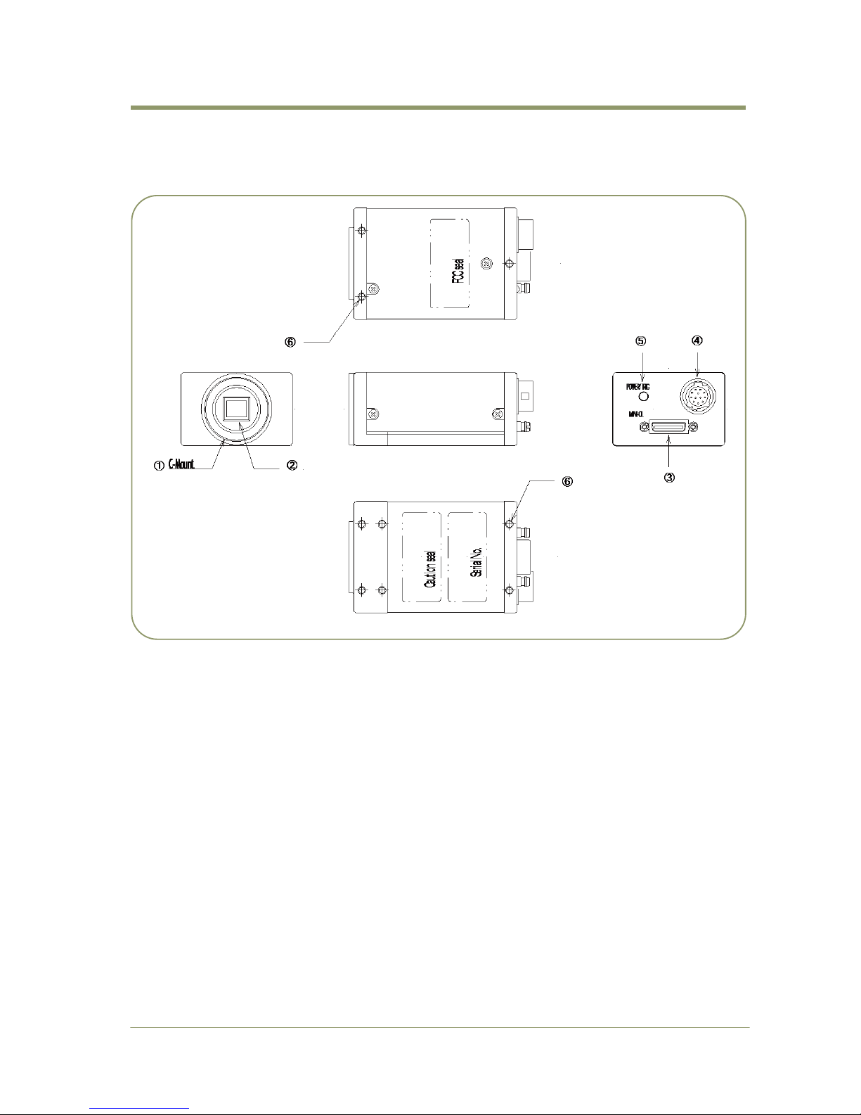
4. Locations and Functions................................................................................. 5
4.1. CM-140 MCL / CB-140 MCL......................................................................... 5
4.2. CM-140 PMCL / CB-140 PMCL...................................................................... 6
5. Pin Assignment............................................................................................ 7
5.1. 12-pin Multi-connector (DC-IN/Trigger) –MCL-version only.................................. 7
5.2. Digital Output Connector for Mini-CL (Camera Link) .......................................... 8
5.2.1. CM-140 MCL / CB-140 MCL ................................................................. 8
5.2.2. CM-140 PMCL / CB-140 PMCL .............................................................. 8
5.3. Input and output circuits .......................................................................... 9
5.3.1. Iris video output ............................................................................. 9
5.3.2. Trigger input ................................................................................. 9
5.3.3. XEEN output .................................................................................. 9
5.3.4. Camera Link interface ...................................................................... 9
6. Functions and Operations ..............................................................................10
6.1. Basic functions .....................................................................................10
6.1.1. Digital Video Output (Bit Allocation)....................................................10
6.1.2. Electronic Shutter ..........................................................................11
6.1.3. Continuous operation or triggered operation ..........................................11
6.1.4. Iris video output. ...........................................................................11
6.1.5. Rear panel indicator. ......................................................................11
6.1.6. Auto-detect LVAL-sync / async. accumulation ........................................12
6.1.7. Starting pixel - Bayer color mosaic ......................................................12
6.1.8. Vertical Binning.............................................................................13
6.2. Sensor Layout and timing .........................................................................14
6.2.1. CCD Sensor Layout .........................................................................14
6.2.2. Horizontal timing ...........................................................................15
6.2.3. Vertical timing ..............................................................................15
6.2.4. Partial Scan..................................................................................16
6.2.5. Vertical Binning.............................................................................17
6.3. Operation Modes ...................................................................................18
6.3.1. Continuous operation ......................................................................18
6.3.2. Pre-select Trigger Mode ...................................................................19
6.3.3. Pulse Width Trigger Mode ................................................................21
6.3.4 Reset Continuous (RCT) trigger mode .......................................................23
6.4. Mode and function matrix. .......................................................................24
7. Configuring the Camera ................................................................................25
7.1. RS-232C control ....................................................................................25
7.2. Setting functions ...................................................................................26
7.2.1. Bit allocation. BA=0, BA=1 ...............................................................26
7.2.2. Partial scan. SC=0 through 4..............................................................26
7.2.3. Vertical binning. VB=0, VB=1 ............................................................26
7.2.4. Shutter mode. SM=0 and SM=1 ...........................................................26
7.2.5. Trigger input select. TI=0, TI=1. .........................................................26
7.2.6. Trigger polarity. TP=0, TP=1. ............................................................26
7.2.7. Gain level. GA=-84 through +336. .......................................................26
7.2.8. Black level. BL=0 through BL=1023. .....................................................26
7.3. Save and Load Functions..........................................................................26
7.4. CM/CB-140MCL / CM/CB-140PMCL command list .............................................27
8. Camera Control Tool for CM/CB-140 MCL / CM/CB-140 PMCL ...................................29