J&E Hall JABC-1 User manual
JABC-1
AMBIENT BEVERAGE COOLER
ISSUE: 01.06.2023
CELLAR COOLER RANGE
TECHNICAL MANUAL
Issue: 01.06.2023 Page II
IMPORTANT!
READ BEFORE PROCEEDING!
GENERAL SAFETY GUIDELINES
This guideline is intended for users to ensure safe
installation, operation, and maintenance of J & E Hall
Ambient Beverage Cooler. This guideline is not intended to
replace the system expertise available from the system
manufacturers.
Only qualified and authorized personnel, who are familiar
with refrigeration systems and components including all
controls, should perform the installation and start-up of this
equipment. To avoid potential injury, use care when
working around sharp edges of metal cabinets. All
electrical wiring should be installed in accordance with all
applicable codes, ordinances, and local by-laws. No work
should be undertaken on any equipment without first
ensuring all electrical supplies are isolated.
Please be aware that during operation, even if the JABC
unit is electrically isolated at its own supply, there may be
terminals within it which are still LIVE. Ensure that the source
of the supply is also isolated before attempting any service
or maintenance operations.
SAFETY SYMBOLS
The following symbols are used in this document to alert the
reader to specific situations:
WARNING
Warning! Risk of serious
injury or death to person!
CAUTION
Caution! Danger which can
lead to serious damages!
NOTICE
Notice! Risk of damage to
equipment!
NOTICE
Disposal requirement:
Your refrigeration product is marked with this
symbol. This means that electrical and
electronic products shall not be mixed with
unsorted household waste. Do not try to
dismantle the system yourself: the dismantling
of the refrigeration system, treatment of the
refrigerant, of oil and of other parts must be
done by a qualified installer in accordance with relevant
local and national legislation. Refrigeration equipment must
be treated at a specialized treatment facility for re-use,
recycling, and recovery.
By ensuring this product is disposed of correctly, you will
help to prevent potential negative consequences for the
environment and human health. Please contact J & E Hall
for more information.
Batteries must be removed from the controller if applicable
and disposed of separately in accordance with relevant
local and national legislation.
Contents
NOMENCLATURE ............................................................1
Figure 1: Product Nomenclature ...............................1
PRODUCT FEATURES.......................................................1
SPECIFICATIONS .............................................................1
Table 1: Unit Performance Data ...............................1
Table 2: Unit Dimension ............................................1
Table 3: Packing List..................................................1
Table 4: Installation Kit .............................................1
OPERATION.....................................................................1
HEALTH AND SAFETY.......................................................2
AIR FLOW CALCULATIONS ...............................................2
Table 5: Maximum Air Pressure Resistance ..............2
Table 6: Pressure Resistance for Ducting ..................2
INSTALLATION.................................................................3
CHANGING AIR SPIGOT POSITION ..........................................3
Figure 2: Diagram for Changing Air Spigot ...............3
Figure 3: Front View Inside Cellar Room ...................3
Figure 4: Side View - Air Inlet Hole Through Wall .....3
Figure 5: Wall Mounting Holes .................................3
Figure 6: Spigot Positions..........................................4
ELECTRICAL CONNECTION ...............................................4
PROBE POSITIONING ...........................................................4
COMMISSIONING............................................................4
Table 7: Pilot Light Indication....................................4
APPENDIX .......................................................................5
Table 8: Alarm Indication ..........................................5
Figure 7: Outline Drawing .........................................5
Figure 8: Wiring Diagram..........................................5
SERVICE & MAINTENANCE ..............................................6
Figure 9: View of Control Panel.................................6
Table 9: Item List in Control Panel ............................6
Table 10: Trouble Shooting .......................................6
Figure 10: Declaration of Conformity........................7
Figure 11: EU Declaration of Conformity ..................8
Issue: 01.06.2023 Page 1
Nomenclature
Figure 1: Product Nomenclature
Product Features
The JABC-1 is primarily used for cooling beer cellars. Cold
air is drawn from outside by the fan through the washable
air filter and distributed into the cellar space. The unit
consists of a fan motor, washable filter, controllers, air
damper, and a pre-wired electrical control box all housed
within a powder coated steel casing.
Operation is via two electronic temperature controls –one
an ambient controller and the other a cellar controller. Each
controller has one temperature probe –the ambient probe
being positioned outside by the air intake grille and the
cellar probe being positioned in a suitable position within
the cellar space (ideally by the main cellar cooler
temperature sensor).
Details of the product:
•Refrigerant free –environmentally conscious
•Washable/reusable air filter
•EBM fan motor with multi-speed capability –can be
adjusted to suit room size
•Interchangeable air inlet damper location –either rear
or base mounting
•Uses standard 150mm diameter ducting
•Fully pre-set controllers
•Inbuilt timer to allow cellar cooler to run for 1 hour per
day (winter operation)
•Switching relay allows operation with all types of
cellar coolers
Specifications
Table 1: Unit Performance Data
Fan
Speed
Air Flow
(m³/h)
Current
Drawn (A)
Power
Input (W)
Sound
dB(A) @
1m
4
684
0.99
231
69.8
3
576
0.87
200
65.0
2
468
0.80
178
56.4
1
252
0.65
147
43.8
•Above data are rated at 230Vac/1phase/50Hz.
•For fan speed setting, refer to section air flow calculation.
Table 2: Unit Dimension
Overall Dimension (mm)
Mounting Dimension
(mm)
Dry
Weight
(kg)
W
D
H
W
D
349
381
484
Refer Figure 5
12
Table 3: Packing List
Item
Quantity
Ambient Cooler
1 pcs
Supply Cable 3C0.75 (Without Plug) 2m
1 pcs
Bracket Support L- shaped (Painted)
2 pcs
M5x10 Hex. Philip Flange Thread Rolling
Screw
2 pcs
M5 Nylon Flat Washer
2 pcs
Cable Glands M12
3 pcs
Fixing Hole Template
1 pcs
Technical Manual
1 pcs
An installation kit is available separately.
Table 4: Installation Kit
Item
Quantity
Plastic Ducting OD150mm, length 500mm
1 pcs
External Air Grille
1 pcs
Internal Door Grille
2 pcs
Air Filter for Spare
1 pcs
Operation
The JABC unit is designed to operate when the external
ambient temperature is 8°C or below and the cellar
temperature rises above its setpoint of 10°C. The JABC fan
motor will draw external cool air into the cellar –passing
through the air filter and cooling the space until the set
temperature of 10°C is reached. If the cellar temperature
continues to rise with the JABC unit running, at 13°C the
main cellar cooler unit will cut in and run along with the
JABC to provide additional cooling until the setpoint
temperature is reached. At this point, both the JABC and the
main cellar cooler will cut off. The JABC unit will not
operate if the external ambient temperature is above 8°C.
At external ambient temperatures of above 8°C, only the
main cellar cooler system will operate.
The JABC unit is designed to be the main control for the
cellar temperature, utilizing both external air when
available and the main cellar cooler as required. The main
cellar cooler controller should be set to the same operating
temperature as the JABC unit.
•An inbuilt timer within the controller allows the main
cellar cooler to run for one hour every 24 hours. This
ensures that the main cellar cooler will still run during
winter periods.
Generation
1: 1st Generation
1
JABC-
Product Type
JABC: J & E Hall Ambient Beverage Cooler

Issue: 01.06.2023 Page 2
Health and Safety
General information
Before Installation
•On receipt of the product, all items should be visually
inspected, and any damage or shortage should be
advised to the supplier immediately.
•Ensure that the correct voltage supply is available for
the unit requirement. Damage to electrical components
within the unit will occur if this is not observed.
•Check that the proposed equipment location is suitable
and provides adequate support for the weight of the
unit.
•Check the proposed equipment location for mains
services (gas, electric water etc.) before drilling holes
for ventilation duct and unit fixings.
•If using external ducting arrangement, ensure ducting
route will fall within the limitation of pressure resistance
as listed in Table 5.
During Installation and subsequent maintenance
•Installation and maintenance are to be performed only
by qualified personnel who are familiar with local
codes and regulations and experienced with this type
of equipment.
•If lifting equipment is required, ensure that it is suitable
for purpose, certificated and that the operatives are
qualified to use it.
•Safe working methods are identified, and operators
have suitable Personal Protective Equipment (PPE).
•Ensure the working area is clear of obstructions.
•The units contain moving parts and electrical power
hazards, which may cause severe injury or death.
Disconnect and shut off power before installation or
service of the equipment.
•Units must be earthed.
•The electrical covers and fan guards must remain fitted
all the time.
•Use of the units outside of the design conditions and the
application for which the units were intended may be
unsafe and be detrimental to the units, regardless of
short- or long-term operation.
•The units are not designed to withstand loads or stress
from other equipment or personnel. Such extraneous
loads or stress may cause failure or injury.
Air Flow Calculations
For effective operation, the cellar will require between 6 to
10 air changes per hour. To calculate the fan speed setting
needed to achieve the required air change:
•Calculate room volume in m³ (L x W x H)
•Multiply the resulting room volume by a value between
6 and 10 (air changes/hour) to achieve a required
figure in m³/h.
•Check the figure against the airflow values (m³/h) for
the fan given in Table 1 and select the fan speed which
best matches this.
The JABC unit comes with a rear entry air inlet connection
for direct attachment to an external facing wall (through-
wall installation). If an external facing wall is unavailable,
the JABC unit can be mounted in a suitable location, with
the air inlet connection changed to bottom entry. This is
done by exchanging the rear inlet spigot with the bottom
entry sealing plate for ducting purpose. Refer Page 3for
instructions on how to change the inlet spigot position.
When connecting ducting to the JABC unit, it is
recommended that any increase in pressure resistance
should be limited as follows:
Table 5: Maximum Air Pressure Resistance
Fan Speed
Maximum Pressure Resistance (Pascals)
4
90
3
118
2
114
1
60
For 150mm nominal diameter lightweight ducting, the
following standard industry values could be used to
calculate the pressure resistance for the proposed ducting
run:
Table 6: Pressure Resistance for Ducting
150mm Circular Duct
Pressure Resistance (Pascals)
1 metre straight length
7
1no. 900bends
15
1no. 450bends
7.5
Example calculation:
Room volume is 6m x 5m x 2.4m (72m³). Multiply this figure
by 8 (air changes/hour). This gives a required figure of
576m³/h.
Refer Table 1, either fan speed 3 or 4 will give the
required airflow to achieve 8 air changes per hour.
Installation requires: 6m of straight ducting, 2no. 900bends
and 2no. 450bends
Calculation : (6 x 7 Pascals) + (2 x 15 Pascals) + (2 x 7.5
Pascals) = 87 Pascals
Assessment: Refer Table 5, 87 Pascals resistance is within the
limits of the fan at either fan speed 3 or fan speed 4.
Room Air Balance
As the unit can provide up to approximately 700m³/h of
airflow into the cellar, this will need to be balanced by
allowing air outlet from the room. This can be done by
fitting an air grille in the cellar door (provided in the
optional installation kit) or by other means.
Fan speed 1 should only be used for
through-wall applications with small room
sizes. For extended ducting application, we do
not recommend using the unit with fan speed 1.
Regardless of room size, please select either fan speed 2,
3 or 4 only.
Issue: 01.06.2023 Page 3
Installation
1. Ensure that the outside wall is clear of any obstructions.
2. Ensure that the selected wall is strong enough to
support the unit.
3. Ensure that no other exhausts will blow directly into the
air inlet duct.
4. Ensure that all hidden cabling/pipework are checked
before any drilling commences.
5. Ensure that fixings are suitable for the application.
6. Do not position the unit directly opposite the airflow
from the main cellar cooler.
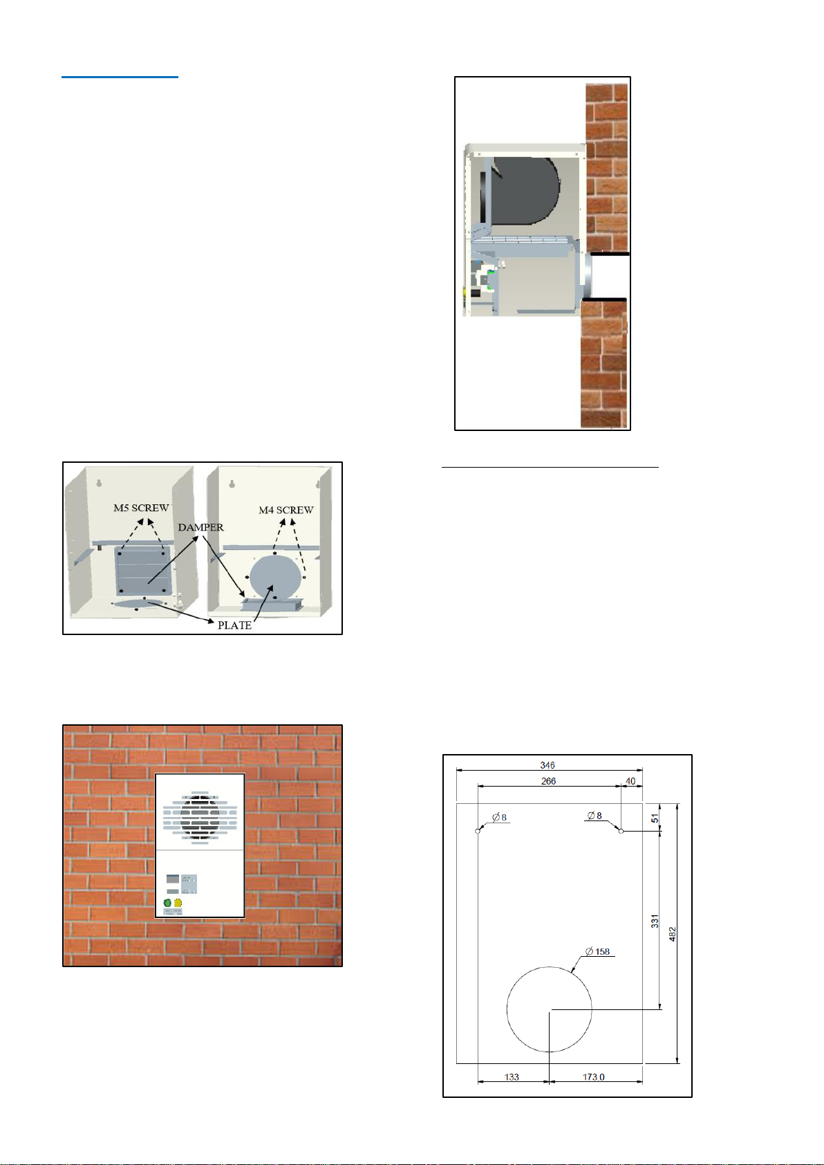
Changing Air Spigot Position
Before installation of the unit, follow these steps to change
the position of the air spigot.
1. Remove blanking plate from the bottom of the unit.
2. Unscrew the damper and interchange the damper from
rear to bottom of unit from inside.
3. Screw the damper to bottom panel using existing M5
screws.
Figure 2: Diagram for Changing Air Spigot
Cover the hole in rear panel using plate and fix using the
existing M4 screw.
Figure 3: Front View Inside Cellar Room
Figure 4: Side View - Air Inlet Hole Through Wall
Wall drillings for direct ducting of unit
1. Drill the wall fixing points and the hole for the air inlet
duct, following the dimensions as shown on below or
follow template supplied.
2. Recommended drill dimension is 157mm diameter for
the air inlet duct.
3. Attach required length of 150mm Ø ducting to air
spigot and seal joint with duct tape or silicon.
4. Pass ambient air probe down inside of ducting. Coil
and cable tie excess cable neatly.
5. Remove the top cover of unit for access to fixing holes
and fix to wall.
6. Fix the 2 brackets, one each side of unit using M5
screws and fix to wall.
7. Seal ducting to hole and fix external air grille to
ducting.
8. Position ambient air sensor.
Figure 5: Wall Mounting Holes
Other manuals for JABC-1
1
Table of contents
Other J&E Hall Accessories manuals


