J&E Hall Cellar Plus 70-S1 User manual

CELLAR PLUS CELLAR COOLER
RANGE
ISSUE: 01.07.2020
CELLAR COOLER RANGE
TECHNICAL MANUAL

Issue: 01.07.2020 Page 2
Contents
Standard Product Configuration 3
Specifications
Capacity data 4
System data 4
Unit dimensions & weights 5
Electrical data & requirements 5
Outdoor unit sound spectrum 5
Health & Safety
General information 6
Installation
Quick Guide-Piping 7-8
Quick Guide- Wiring 9
Unit location 10
Installation clearances 11
Field piping 12
Pressure testing 13
Evacuation & charging 14
Drainage 15
Electrical 16
Commissioning
General 17
Pre startup checks/running the unit/compressor operation 18
Vacuum Operation 19
Safety pressure switch setting 19
High pressure safety 19
Low pressure safety 19
Compressor operating pressures 19
Service & Maintenance 20-21
F-Gas Information 22
Drawings
Indoor unit dimensions (40E) 23
Indoor unit dimensions (50E & 60E) 23
Indoor unit dimensions (80E) 24
Outdoor unit dimensions 25-26
Electrical wiring diagrams (Indoor) 27
Electrical wiring diagrams (Outdoor) 28-29
Technical Information
Dixell electronic controller 30
Controller parameters 31
Dual Pressure Switch 32
Certification 33

Issue: 01.07.2020 Page 3
Standard Product Configuration
Indoor
•Brewery specification 6 fins per inch evaporator coils
•Galvanised mild steel casing with polyester powder coating
•Electronic controller
•3/4” BSP drain fitting on evaporator
Outdoor
•Housed condensing units
•Copeland scroll compressor
•Basic control box
•Adjustable LP/HP switch fitted
•Drier & sight glass fitted
•Acoustic insulation
General
•Single & Twin Evaporator systems
•Cellar temperatures down to +4°C
•Suitable for cooling beers, wines, flowers, fruit & vegetables etc.
Range
Single Evaporator Systems:
•Cellar Plus 70-S1/S3
•Cellar Plus 80-S1/S3
Twin Evaporator Systems:
•Cellar Plus 70-T1/T3
•Cellar Plus 80-T1/T3
•Cellar Plus 90-T1/T3

Issue: 01.07.2020 Page 4
Specifications
System data
Capacity data
Unit Model
Air Flow
(m3/h)
Noise
Level(2)
dB(A)
Unit Model
Pipe Connections
(Inlet/Outlet)
Air Flow
(m3/h)
Air
Throw(3)
(m)
Noise
Level(2)
(10m)
dB(A)
BSCU-30-M1
BSCU-30-M3
BSCU-35-M1
BSCU-35-M3
BSCU-30-M1
BSCU-30-M3
BSCU-35-M1
BSCU-35-M3
BSCU-40-M1
BSCU-40-M3
(1) Nominalcapacity stated at Troom10ºC / 32ºC Ta with R448A/R449A refrigerant.
(2) Noise levels are measured in an anechoic chamber at nominaltest conditions (Troom10ºC / 32ºC Ta). Different conditions may produce different results.
(3) Air throws are based on a finalvelocity of 0.4 m/s.
1/2"& 7/8"
System
Outdoor Units
IndoorUnits
Max.
Pipe
Run (m)
Pipe Connections
(Inlet/Outlet)
50
CellarPlus 70-S1/S3
CellarPlus 80-S1/S3
CellarPlus 70-T1/T3
CellarPlus 80-T1/T3
CellarPlus 90-T1/T3
3/8"& 3/4"
1/2"& 3/4"
3/8"& 3/4"
1/2"& 3/4"
6.90
2765
50
50
50
50
System
COP
3350
1/2"& 5/8"
1/2"& 3/4"
1/2"& 3/4"
7.94
Nominal
Capacity (1)
(kW)
1x JCC2-80E
2x JCC2-40E
2x JCC2-60E
1x JCC2-80E
34
36
34
2765
(2x)
2560
1/2"& 5/8"
4250
3350
36
41
1/2"& 3/4"
(2x)
2680
4070
4070
(2x)
2270
10
10
10
2.20
2.21
2.27
2.14
50
50
(2x)
48
(2x)
47
(2x)
47
7.17
7.93
9.19
2.25
10
2x JCC2-50E
10
4 6 8 10 12 14 16
27 5.78 6.26 6.73 7.21 7.69 8.17 8.64
32 5.53 5.99 6.44 6.90 7.35 7.81 8.26
38 5.16 5.61 6.05 6.50 6.95 7.40 7.85
27 6.81 7.27 7.73 8.18 8.64 9.10 9.55
32 6.75 7.10 7.52 7.94 8.35 8.77 9.19
38 6.71 7.01 7.32 7.62 7.93 8.23 8.53
27 6.55 6.87 7.18 7.50 7.82 8.13 8.45
32 6.27 6.57 6.87 7.17 7.47 7.78 8.08
38 5.23 5.64 6.06 6.47 6.88 7.29 7.71
27 6.70 7.19 7.68 8.17 8.67 9.16 9.65
32 6.57 7.02 7.47 7.93 8.38 8.83 9.28
38 6.62 6.94 7.26 7.57 7.89 8.20 8.52
27 8.40 8.80 9.20 9.61 10.01 10.41 10.81
32 8.01 8.40 8.80 9.19 9.59 9.98 10.38
38 7.53 7.92 8.31 8.70 9.08 9.47 9.86
CellarPlus 70-S1/S3
CellarPlus 80-S1/S3
CellarPlus 70-T1/T3
CellarPlus 80-T1/T3
CellarPlus 90-T1/T3
Troom(ºC)
Ta (0C)
System
Cooling capacities in kW (R448A/R449A)

Issue: 01.07.2020 Page 5
Specifications
Unit dimensions & weights
Electrical data & requirements
Outdoor unit sound spectrums
Unit Model W x D x H
(mm)
Fixing Ctrs.
(mm)
Weight
(kgs)
Unit Model W x D x H
(mm)
Fixing Ctrs.
Top(mm)
Fixing Ctrs.
Rear(mm)
Weight
(kgs)
BSCU-30-M1 77
BSCU-30-M3 76
BSCU-35-M1 97
BSCU-35-M3 96
BSCU-30-M1 77
BSCU-30-M3 76
BSCU-35-M1 97
BSCU-35-M3 96
BSCU-40-M1 107
BSCU-40-M3 107
826 x 122
826
(2x)
36
826 x 122
826
(2x)
38
63
2x JCC2-40E
865 x 505 x 489
745 x 122
CellarPlus 70-T1/T3
CellarPlus 80-S1/S3
1334 x 530 x 864
946 x 500
1x JCC2-80E
System
Outdoor Units
Indoor Units
1437 x 505 x 557
1173 x 324
1173 x 310
63
1173 x 310
CellarPlus 70-S1/S3
1108 x 478 x 649
703 x 448
1x JCC2-80E
1437 x 505 x 557
1173 x 324
745
(2x)
33
CellarPlus 80-T1/T3
1334 x 530 x 864
946 x 500
2x JCC2-50E
904 x 504 x 546
CellarPlus 90-T1/T3
1351 x 530 x 864
946 x 500
2x JCC2-60E
904 x 504 x 546
1108 x 478 x 649
703 x 448
Unit Model
Power
Supply
(V/ph/Hz)
Power
(kW)
MCC (2)
(A)
LRA (2)
(A)
RRC (1)
(A)
SFR (3)
(A)
Unit Model
Power
Supply
(V/ph/Hz)
Power
(kW)
RRC (1)
(A)
SFR (3)
(A)
BSCU-30-M1 230/1/50 21.5 82.0 12.2 25
BSCU-30-M3 400/3/50 10.3 40.0 5.1 16
BSCU-35-M1 230/1/50 25.0 97.0 14.0 32
BSCU-35-M3 400/3/50 9.0 46.0 5.7 20
BSCU-30-M1 230/1/50 21.5 82.0 13.3 25
BSCU-30-M3 400/3/50 10.3 40.0 5.4 16
BSCU-35-M1 230/1/50 25.0 97.0 14.3 32
BSCU-35-M3 400/3/50 9.0 46.0 5.8 20
BSCU-40-M1 230/1/50 28.0 114.0 17.4 40
BSCU-40-M3 400/3/50 11.0 50.0 6.8 20
(1) Power consumption and Rated Run Current (RRC) shown at nominal test condition (Troom10ºC / 32ºCTa) with R448A/R449A refrigerant
(2) Maximum Continous Current (MCC) and Locked Rotor Amps (LRA) are for the unit compressor only.
(3) SFR ~ Suggested Fuse Rating (Motor Rated for Outdoor Unit)
0.43
0.43
0.45
0.44
2.70
3.08
230/1/50
1.9
6
0.44
System
CellarPlus 70-S1/S3
CellarPlus 80-S1/S3
CellarPlus 70-T1/T3
CellarPlus 80-T1/T3
CellarPlus 90-T1/T3
2.90
3.17
3.65
OutdoorUnits
Indoor Units
230/1/50
2.0
6
2.0
6
2.0
6
1.9
6
2x JCC2-50E
2x JCC2-60E
230/1/50
230/1/50
1x JCC2-80E
1x JCC2-80E
2x JCC2-40E
230/1/50
125 Hz 250 Hz 500 Hz 1 kHz 2 kHz 4 kHz 8 kHz A (dBA) A (dBA)
BSCU-30-M1/M3 62.1 56.7 51.3 48.2 43.1 38.3 31.3 54.1 34
BSCU-35-M1/M3 63.5 62.7 53.1 48.6 43.9 38.8 32.4 56.3 36
BSCU-40-M1/M3 61.4 61.7 58.6 55.2 51.7 48.3 43.1 60.7 41
Model
1/1 Octave Sound Pressure Levels @ 1 meter fromfront of the unit
Noise Levels
(10m)
Frequency

Issue: 01.07.2020 Page 6
Health and Safety
General information
Before Installation
•Ensure the units received are the correct models for the intended application.
•Ensure the refrigerant, voltage and MWP are all suitable for the proposed application.
•Check there is no damage to the units. Any damage should be advised to the supplier immediately.
•Check that the proposed equipment locations are suitable and provide adequate support for the weight of the units.
During Installation and subsequent maintenance
•Installation and maintenance are to be performed only by qualified personnel who are familiar with local codes and
regulations, and experienced with this type of equipment.
•If lifting equipment is required, ensure that it is suitable for purpose, certificated and that the operatives are qualified to use
it.
•Safe working methods are identified and operatives have suitable PPE.
•Ensure the working area has adequate ventilation during brazing procedures.
•The units contain moving machinery and electrical power hazards, which may cause severe injury or death. Disconnect and
shut off power before installation or service of the equipment.
•Refrigerant release into the atmosphere is illegal. Proper evacuation, recovery, handling and leak testing procedures must be
observed at all times.
•Units must be earthed and no maintenance work should be attempted prior to disconnecting the electrical supply.
•The electrical covers and fan guards must remain fitted at all times.
•Use of the units outside of the design conditions and the application for which the units were intended may be unsafe and be
detrimental to the units, regardless of short or long term operation.
•The units are not designed to withstand loads or stresses from other equipment or personnel. Such extraneous loads or
stress may cause failure/leak/injury.
Important Note:
Only a qualified refrigeration engineer, who is familiar with refrigeration systems and components
including all controls, should perform the installation and start-up of the system. To avoid potential
injury, use care when working around coil surfaces or sharp edges of metal cabinets. All piping and
electrical wiring should be installed in accordance with all applicable codes, ordinances and local by-
laws.

Issue: 01.07.2020 Page 7
Installation
Quick Guide –Piping
Pipework:
Pipework sizing should be based on the total equivalent lengths, which includes equivalent lengths for bends, traps, risers etc. A
guide to sizing is noted below:
Expansion Valves:
Suitably selected externally equalized expansion valves are required for each evaporator. Fitting of the valves should be carried
out as follows:
➢Carefully braze the TEV outlet to the 1/2” evaporator inlet pipe approximately 100mm from the distributor. Protect both
the TEV and distributor from excessive heat using a wet cloth.
➢Connect the liquid line to the 3/8” TEV inlet (preferably using a flare x solder adaptor). Ensure the correct size orifice is
fitted into the valve inlet before assembly and tightening.
➢Make an equalization connection between the TEV and the suction line as per the TEV instructions.
➢Fit the valve phial sensor to the suction line as per the TEV instructions once all brazing has been completed.
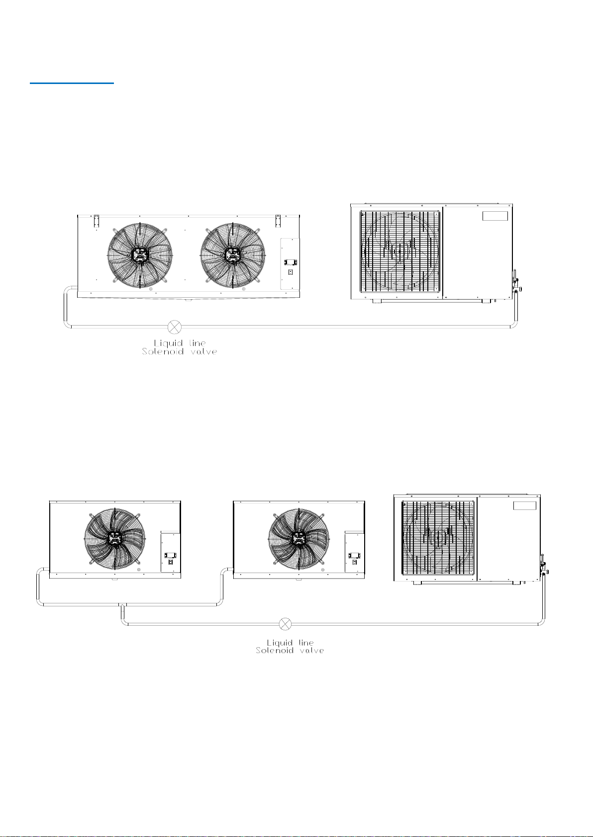
Solenoid Valve:
A suitably sized solenoid valve needs to be installed in the liquid line just before the TEV on single evaporator systems and just
before the ‘T’ piece in the main liquid line on Twin Systems (as shown on page 8). The liquid line solenoid valve is not supplied in
both Single and Twin system.
Liquid Suction Liquid Suction Liquid Suction
3/8" 3/4" 3/8"
7/8" 3/8" 7/8"
(2x 3/8") (2x 5/8") (2x 3/8") (2x 5/8") (2x 3/8") (2x 5/8")
1/2" 7/8" 1/2" 7/8" 1/2" 7/8"
(2x 3/8") (2x 5/8") (2x 3/8") (2x 5/8") (2x 3/8") (2x 5/8")
1/2" 7/8" 1/2" 7/8" 1/2" 1 1/8"
(2x 3/8")
(2x 3/4") (2x 3/8") (2x 3/4") (2x 3/8") (2x 3/4")
- The pipe sizes indicated in brackets are fromthe ' T 'piece to each evaporator.
- Pipeworkshould be selected on the total equivalent length of run between allunits.
Condensing Unit
Model
Evaporator
Models
1x JCC2-80E
1x JCC2-80E
2x JCC2-60E
BSCU-40-M1/M3
10m
20m
30m
CellarPlus 90-T1/T3
BSCU-30-M1/M3
BSCU-35-M1/M3
BSCU-30-M1/M3
BSCU-35-M1/M3
CellarPlus 70-S1/S3
3/8"
7/8"
CellarPlus 70-T1/T3
2x JCC2-40E
3/8"
7/8"
CellarPlus 80-S1/S3
1/2"
7/8"
1/2"
System
- The pipe sizes indicated in boldare fromcondensing unit to ' T ' piece.
CellarPlus 80-T1/T3
7/8"
3/4"
3/8"
7/8"
2x JCC2-50E
Pipe Sizing: 10ºC CellarR448A/R449A
1/2"
1x TE2-03
1x TE2-04
TEV Model
2x TE2-02
2x TE2-02
2x TE2-02
Issue: 01.07.2020 Page 8
Installation
Quick Guide –Piping
Single System
Twin System

Issue: 01.07.2020 Page 9
Installation
Quick Guide - Wiring
Evaporators:
The JCC indoor evaporators require a 6A single phase supply. For Twin Systems, both evaporators can be connected to a single
mains supply. Separate mains supplies can be installed if required but it is desirable for them to be taken from the same supply
phase. There are no mains isolators fitted to the evaporators.
On the Lead evaporator for Twin Systems, terminals P1 & P2 must be fitted with a link wire to disable the low-pressure switch
fitted on the evaporator coil (see wiring diagram on page 27). The low-pressure switch fitted to the condensing unit once set up
will control the pump down operation.
Lead/Lag Connection (Twin):
The JCC evaporators come pre-fitted with an electronic controller as standard. For the Twin Systems, one of the evaporators
needs to be designated as the Lead Unit with the other being the Lag Unit. The Lead Unit controls the cellar temperature by
operation of the liquid line solenoid valve. The Lag Unit has no control over system operation and will just provide cellar
temperature indication. Please refer to wiring diagram on page 27.
Condensing Unit:
The outdoor condensing unit requires either a single-phase supply or a three-phase supply depending on the unit model selected.
A mains isolator is required as there is no isolator fitted to the condensing unit. Please refer to wiring diagrams on pages 28-29.
There is no need for any interconnecting wiring between the indoor and outdoor units as the outdoor unit will operate in pump
down mode via the low-pressure switch.
Issue: 01.07.2020 Page 10
Installation
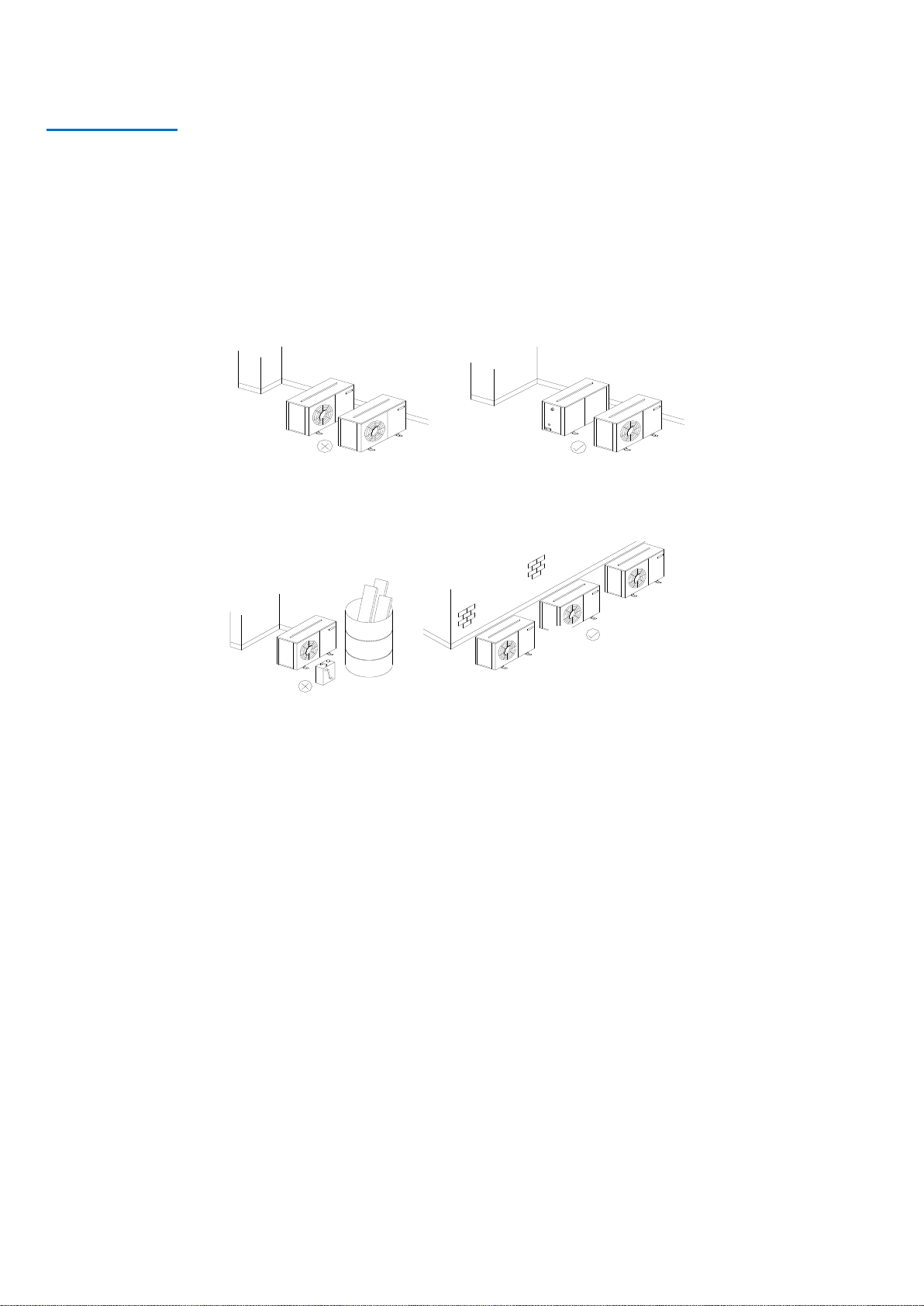
Unit location
•In order to achieve maximum cooling capacity, the installation location for the condensing unit should be carefully selected.
•Install the condensing unit in such a way so that hot air ejected by the condensing unit cannot be drawn in again (short circuit
of hot discharge air). Allow sufficient space for maintenance around the unit.
•Ensure that there is no obstruction to air flow into or out of the unit. Remove obstacles which block air intake or discharge.
•The location must be well ventilated, so the unit can draw in and distribute plenty of air thus lowering the condensing
temperature.
•To optimize the unit running conditions, the condenser coil must be cleaned at regular intervals.
The evaporators can be mounted directly to a wall or to the ceiling utilizing the fixing holes on the rear of the unit or on the top of
the unit. No additional brackets are required. Position the evaporators where the optimum airflow can be achieved. Avoid
locating in corners or in alcoves which may restrict airflows. A minimum 10mm rawlbolt type fixing is required with a large steel
washer to bear the unit weight. It is important to ensure that the wall/ceiling is able to withstand the unit weight and that all
fixings are secure.
Both indoor and outdoor units must be level in all directions.
✓
✓
X
X

Issue: 01.07.2020 Page 11
Installation
Installation clearances
•The installation location should allow sufficient space for air flow and maintenance around the units:
Outdoor
Indoor
500mm 500mm
1500mm to
any obstruction
Minimum 1800mm from
floor level

Issue: 01.07.2020 Page 12
Installation
Field piping
To ensure satisfactory operation and performance, the following points should be noted for field piping
arrangements:
•Pipework routes must be as simple and as short as possible.
•Avoid low points on pipework where oil can accumulate.
•Use only clean, dehydrated refrigeration grade copper tube with long radius bends.
•When brazing use only silver alloy rods.
•Run braze without over filling to ensure there is no leakage into the tube.
•To prevent oxidization, blow oxygen free nitrogen through pipework when brazing.
•Protect the casing of the unit when brazing connections.
•Install insulation with a minimum wall thickness of 1/2” on all suction lines.
•Adequately support all pipe work at a maximum of 2 metre intervals.
Use of incorrect pipe sizes can affect system pressures/temperatures and gas velocity for proper oil return.
Important Note:
One of the main factors affecting equipment reliability and compressor service life is refrigeration
circuit contamination. During installation, circuit contamination can be caused by:
•Brazing & Welding Oxides
•Filings & Particles from de-burring pipework
•Brazing Flux
•Moisture & Air
Important Note:
The guidelines for pipe sizing and maximum lengths as shown on page 7 should be followed. All
local codes of practice must be observed in the installation of refrigerant piping.

Issue: 01.07.2020 Page 13
Installation
Pressure testing
Both the indoor and outdoor units have been pressure tested in the factory prior to dispatch and contain a
holding charge of oxygen free nitrogen.
Once the pipework installation is complete, it should be pressure tested prior to evacuation to test for leaks.
A pressure leak test should be carried out using oxygen free nitrogen (OFN). NEVER USE OXYGEN FOR PRESSURE TESTING
SYSTEMS. A calibrated nitrogen pressure regulator must always be used. Before starting any pressure testing, ensure the area
surrounding the system is safe, inform relevant personnel and fit warning signs indicating high pressure testing. Also, use correct
PPE as required.
Listen for any possible leaks and check all joints with bubble spray. If any leaks are discovered, release pressure slowly from
system until empty, repair leak and then restart pressure testing procedure. Never attempt to repair a leak on a pressurized
system.
A strength test should also be incorporated according to local regulations.
Once testing has been completed satisfactorily, release the pressure from the system gradually and safely to external
atmosphere.
Important Note:
Do not open the service valves on the condensing unit until pressure testing procedures have been
carried out.

Issue: 01.07.2020 Page 14
Installation
Evacuation & Charging
Once pressure testing has been completed, the system can now be evacuated to remove air and any moisture from the piping.
This can be done as follows:
•Ensure any nitrogen charge is safely released from the system (including the condensing unit).
•Connect a gauge manifold to the schrader connections on the service valves on the condensing unit.
•Connect a vacuum pump and vacuum gauge to the system.
•Evacuate the system until vacuum is below 250 microns (0.25 torr).
Note: A triple evacuation procedure is recommended for all new systems or where moisture is suspected.
Once the system is isolated and the vacuum pump is switched off, any rise in pressure indicates that either there may be a leak in
the system or moisture is still present. In this case, recheck the system for leaks, repair as necessary, and then restart the
evacuation procedure. Once completed satisfactorily, the vacuum pump and vacuum gauge can be removed.
At this point, refrigerant charge can be added to the system as required. Refrigerant must be charged in the liquid phase into the
liquid receiver/liquid line. Do not charge liquid refrigerant into the suction side of the system.
Important Note:
Moisture prevents proper functioning of the compressor and the refrigeration system. Ensure
that a good quality vacuum pump is used to pull a minimum vacuum of 250 microns (0.25
torr).
Issue: 01.07.2020 Page 15
Installation
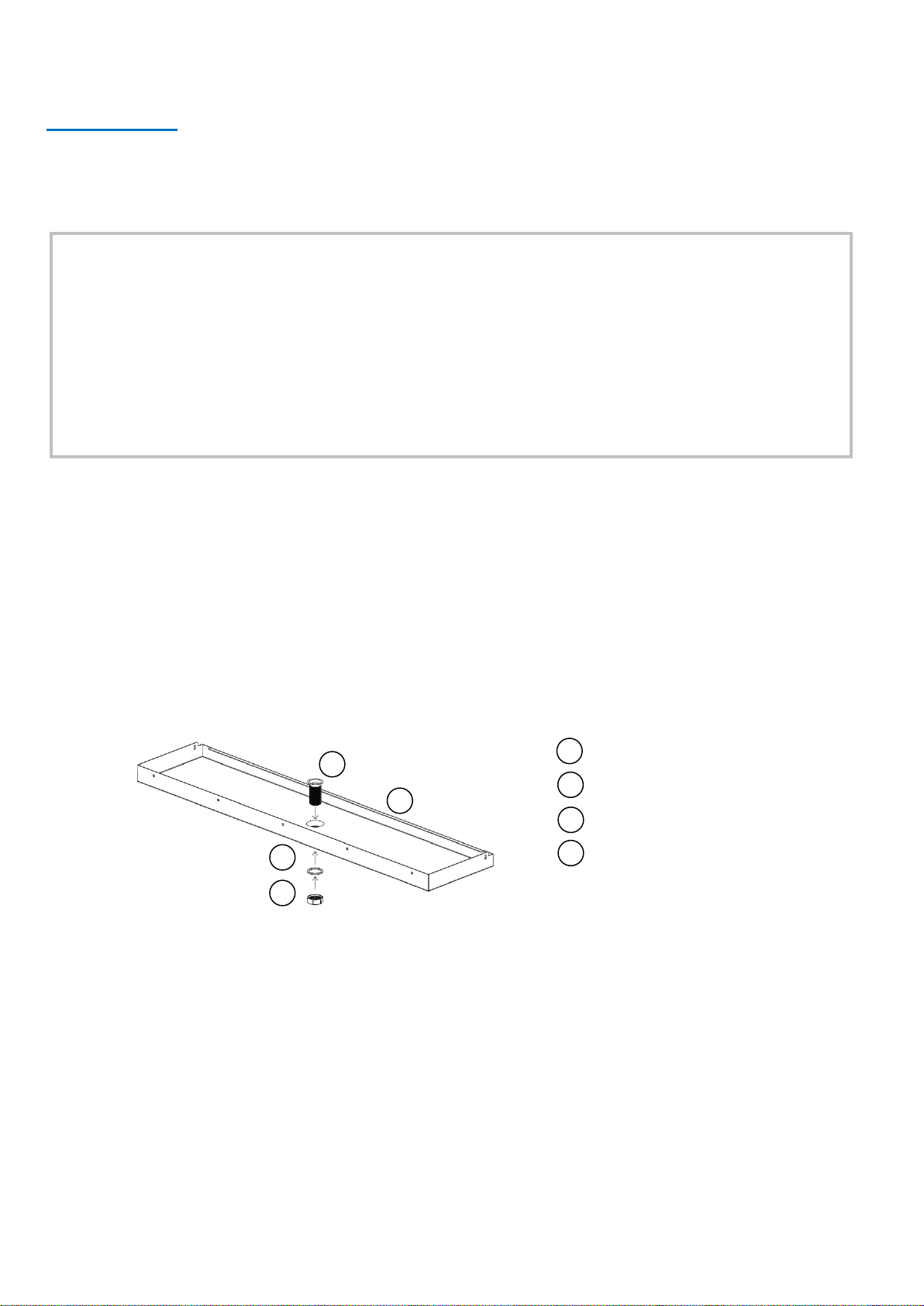
Drainage
The drain fitting is aluminum alloy with a 3/4” BSP male thread. A locknut and an aluminium washer are supplied to secure to the
drain pan. The locknut only requires hand tightening and then pinching up with a spanner. Do not over tighten or the threads may
strip from the nut and also damage the tray. To fit the drain fitting, remove the drip tray (unscrew the seven screws that secure
it), locate the fitting then refit the tray. The correct way to fit the drain fitting to the drain pan with aluminium washer and
locknut can be seen in the diagram below.
A minimum suggested size of drain from the indoor unit is 20mm or 3/4”. This can be either copper or plastic. Flexible hose is not
recommended as it can easily kink causing a blockage and water to back up in the unit.
Important Note:
The evaporator drain pan fitting is supplied loose and must be fitted on site. It is attached to the
indoor unit fan guard with a cable tie. Correct fitting is vital to ensure leak –free operation. The lock
nut on the drain fitting must be fitted the right way around; otherwise it will not tighten against the
drip tray. One side of the nut has an angled recess –this must be facing towards the drip tray. The
fitting does not require any sealant but a small amount of silicon sealant can be applied between the
flared face of the fitting and the drip tray if so desired.
1DRAIN FITTING
2DRAIN PAN
3ALUMINIUM WASHER
4LOCKNUT
1
2
3
4

Issue: 01.07.2020 Page 16
Installation
Electrical
Cable type and sizing must be selected for the particular application and the electrical installation should
conform to the current local standards.
•Cables to the indoor units should be routed through the ‘U’ shaped cut-out in the bottom of the removable air grille at
the side of the units and into the rear of the electric box.
•Cables to the outdoor unit should be routed through the cable glands on the rear of the unit.
•Connect the mains supplies as per the wiring diagrams on pages 27 & 28-29.
Access to the electrical terminals and components on the indoor unit is via the removable cover plate on the front of the unit.
Removal of the cover plate gives access to the contactor, the terminal block as well as the electronic controller and rocker switch
connections.
To gain access to the electrical box on the outdoor unit, remove the screws of the panel located on the right hand side of the unit
and remove the panel. The electrical box is located behind the panel.
Important Note:
The mains electrical supply to the indoor units must be via a suitably rated isolator and circuit breaker
or fuse. There is no isolator fitted to the indoor units. The rocker switch on the front of the indoor
units is for isolating the indoor fan and electronic controller only. The mains electrical supply to the
outdoor unit must be via a suitably rated motor rated circuit breaker or fuse and requires termination
at a suitably rated isolator. There is no isolator fitted to the outdoor units.
J & E Hall cellar systems require a 230V/1/50 supply to the indoor units and either a 230V/1/50 or a
400V/3/50 supply to the outdoor unit (depending on outdoor unit model chosen). They are not
suitable for any other supply voltages (other than a deviation of +/- 10% of the above values) and are
not suitable for 60 Hz supplies.

Issue: 01.07.2020 Page 17
Commissioning
General
Switch on the power at the mains isolators and then switch on the rocker switch on the front of the indoor units. Set the required
operating temperature on the electronic controller (Master controller on Twin Systems) and check the system parameters in the
controller are as required (the controllers are pre-programmed in the factory to suggested settings).
Run the system to the required temperature and check system pressures, gas charge and running currents of motors to ensure
correct operation.
Carry out a manual defrost (press the defrost button on the Master controller for more than 2 seconds) to ensure the defrost
period is adequate to clear any frost build up on the evaporator coil.
Carry out final leak test and ensure all covers are fitted and securing screws are tightened.
Log all information along with system model and serial numbers for future reference.
Ensure that the customer / responsible person is provided with basic operating instructions and where electrical isolators are
situated in case of emergency.
Important Note:
Before starting the system, ensure that all electrical connections are correctly made and tight,
service ports are in the correct position and all covers and guards are fitted.
Important Note:
An anti-short cycle timer is built into the controller to prevent the compressor from stop/starting
too quickly, which can result in the compressor tripping on its internal overload. If the overload
trips, please allow time for it to reset before restarting.

Issue: 01.07.2020 Page 18
Commissioning
Pre startup checks
Before starting the condensing unit, the following checks should be carried out as a minimum:
•Check electrical supply is correct and all connections are sound.
•All moving parts are free and guards fitted.
•Compressor oil level satisfactory.
•Initial settings for safety switches.
•Overload set correctly.
•All valves in correct operating position.
•Initial refrigerant charge.
•Gauge manifold connected to both low and high sides of system.
Running the unit
•Run the unit and check compressor and condenser fan operation.
•Check system pressures and temperatures, gas charge and running currents of motors to ensure correct
operation.
•Check compressor suction superheat. This should be between 10K and 20K at normal operating conditions.
•Final adjustment of safety switch settings.
•Allow the system to run for 3 –4 hours. Check compressor oil level and top up with the correct oil type as
required (RL32-3MAF). Recheck the compressor oil level again after 24 hours operation.
•Carry out final leak test and ensure all panels/covers are fitted and screws tightened.
•Log all information along with the system model and serial numbers for future reference.
•Ensure that the customer / responsible person is provided with basic operating instructions and where
electrical isolators are situated in case of emergency.
Compressor operation
Scroll compressor motors are designed to run only in one direction. This is not an issue with single phase
compressors as they will always run in the correct direction. The correct rotation of a three-phase compressor motor
depends on the connection of the three incoming phases to the unit. Correct rotation can be determined by a drop in
suction pressure and a rise in discharge pressure when the compressor is energized. Running the compressor for a
short period of time in reverse direction will have no negative impact but prolonged running in reverse direction may
cause premature failure. To reverse the rotation of a three-phase scroll compressor, shut off the incoming power
supply to the unit, swap connection of any two of the three incoming phases at the unit isolator, reapply power to
the unit and following compressor restart, recheck operating pressures.
Do not operate scroll compressors in a vacuum condition, as this will cause the scrolls to overheat very quickly
causing premature failure.
Ensure an adequate liquid charge has been introduced to the high side of the system before starting to ensure a
minimum operating pressure on the suction side of 0.5 bar is maintained, otherwise overheating of the scrolls and
subsequent damage may occur.

Issue: 01.07.2020 Page 19
Commissioning
Vacuum Operation
Do not operate scroll compressors in a vacuum condition, as this will cause the scrolls to overheat very quickly causing premature
failure.
Safety pressure switch settings
The Saginomiya DNS pressure switch fitted to the condensing units with auto reset for low pressure and manual reset for high
pressure is NOT factory preset. BOTH THE LP AND HP SWITCH SETTINGS MUST BE ADJUSTED BEFORE STARTING THE UNIT. Be
sure that the high-pressure setting does not exceed the receiver’s maximum service pressure.
High pressure safety
The high-pressure safety switch is required to stop the compressor should the discharge pressure exceed the values shown in the
following table. The high-pressure switch can be set to lower values depending on the ambient conditions.
Low pressure safety
The low-pressure safety switch protects the compressor against deep vacuum operation, a potential cause of failure due to
internal arcing and overheating.
For ZB compressors, the low-pressure cut-out should be set as high as possible.
Care should be taken because the scroll sets will unload at a pressure ratio of approximately 10:1 for ZB compressors.
If the unit fails to pump down, the pump down pressure should be reset to a higher value.
Compressor operating pressures
The compressor operating pressures should be kept within the following limits:
Compressor
Refrigerant
S2/S3 Max. HP Set
Unit Series
ZB
R448A/R449A
27 bar
Compressor
Refrigerant
M in. Cut Out (barG)
M in. Cut Out (psi)
S2/S3
30
2
Unit Series
ZB
R448A/R449A
Compressor
Refrigerant
High Side (barG)
Low Side (barG)
7.1 ~ 27.7
S2/S3
2.0 ~ 7.1
Unit Series
ZB
R448A/R449A

Issue: 01.07.2020 Page 20
Service & Maintenance
The units are designed to give long life operation with minimum maintenance. However, they should be routinely checked and
the following service schedule is recommended under normal circumstances:
1. Indoor and Outdoor units –Inspect at regular intervals
•Check for refrigerant leaks on all joints and fittings.
•Check mountings for tightness and wear.
•Inspect pipework for any damage.
•Check all electrical connections.
•Ensure that no abnormal noise or vibration is detected during test run.
2. Condenser & Evaporator Fan Motors & Blades –Clean and inspect at regular intervals
•Check for abnormal noise, vibration and fan imbalance.
•Ensure that the fan motors are clean and spin freely.
•Check that the fan blades are clean and free from restriction and damage/imbalance.
•Note: The Fan Motors are pre-lubricated and factory sealed so no maintenance is necessary.
3. Condenser & Evaporator Coils –Clean and inspect at regular intervals
•Check and remove the dirt and debris between the fins using a soft brush and/or a suitable chemical coil cleaner then
rinse with clean water.
•Check and remove any obstacles that may hinder the airflow through the coils.
•Repair any damage to fins and ensure any guards are fitted correctly.
•DO NOT USE HIGH PRESSURE WASHERS ON COILS –THEY DAMAGE THE FINS.
4. Controls
•Check controller settings and operation.
•Check calibration of temperature probe reading.
5. Power Supply –Inspect at regular intervals.
•Check the running current and voltage for the units.
•Check the electrical wiring and tighten the wires onto the terminal blocks if necessary.
6. Refrigerant Charge
•Check the refrigerant charge by ensuring that the system is operating correctly and the system pressures are as
expected.
•Carry out a full leak test.
Important Note:
Warning! –Disconnect the mains electrical supply before servicing or opening the
units.
This manual suits for next models
15
Table of contents
Other J&E Hall Accessories manuals


Popular Accessories manuals by other brands


Clever Life
Clever Life CL-S-GS322 Operating and installation instruction

SMC Networks
SMC Networks PSE200 Series Operation manual

MicaSense
MicaSense Altum Integration guide

IFM
IFM efector200 OM installation instructions

LEGRAND
LEGRAND Wattstopper CI-355 installation instructions

Jabra
Jabra ROX WORELESS Getting started guide