manuals.online logo
Brands
  1. Home
  2. •
  3. Brands
  4. •
  5. J&M Corporation
  6. •
  7. Stereo System
  8. •
  9. J&M Corporation INTEGRATR V MI-2034 User manual

J&M Corporation INTEGRATR V MI-2034 User manual

© 2013 J&M Corporation. All rights reserved. 1/13
INTEGRATR™V
#
MI-2034
Motorcycle Audio System
Installation and
Operation Instructions
The IntegratrV (#MI-2034) has been developed to provide
motorcycle riders with the most advanced audio and
communications system available. The IntegratrV allows
owners to utilize privately purchased portable modular
electronic devices such as cell phones, two way radios,
portable music storage devices (MP3/IPOD), along with
navigation (GPS)/highway warning audio devices.
The IntegratrV manages all audio sources as well as
communications with a passenger and other individuals,
whether on motorcycles or other vehicles. There are many
choices available, so it is important to fully understand how to
manage these options to bring the highest level of enjoyment
to you and your passenger. Please read the enclosed manual
completely. The manual provides an overview of the audio
& communications system, a detailed explanation how each
interface operates, and provides an understanding of options
/ accessories available to maximize your enjoyment of the
system.
Overview
The audio management of the IntegratrV consists of inputs and
outputs from numerous standard and optional devices. To gain
the most benefit from the system, it is necessary to understand
what functions are available. As with all audio systems, these
devices operate on different levels, which determine what
priority each level has over the other. These levels go from
lowest priority (level 1) to highest priority (level 4).
Music can be received into the helmet headsets using the
sources listed below:
Level 1 -Auxiliary Audio Input (MP3 players/iPod/FGA-345’s)
Level 2 -Driver/passenger intercom, which mutes level 1 audio
when engaged.
Level 3 -FRS/GMRS radios (462 MHz two-way radios from
Kenwood, Motorola, etc.) will also mute Level 1 audio and mix
with Level 2 intercom when signal is received.
Level 4 -Cell Phone or Navigation (GPS), which mutes level
3 through 1 and also connects rider and passenger helmet
headsets to the cell phone.
Radar detector will momentarily interrupt all lower levels (for
Right helmet speaker only), to signal:
• Accessory Audio Warning Device (equipped with audio output
jack)
The IntegratrV also provides the connection plugs for the rider
/passenger headsets for all of the functions noted above. The
IntegratrV has been optimized to provide excellent music fidelity
for your listening enjoyment.
passenger's
helmet headset
(not included)
driver's
helmet headset
(not included)
intercom volume/vox
sensitivity control
ground to
frame
fuse
holder
inline
noise
filter
12 volt
switchable
optional
FRS/GMRS
connection cable
optional
cell phone
connection
cable
optional
audio warning device
connection cable
handlebar PTT/volume
up/down switch
aux audio
connection
cable
GPS
or
optional
GPS
connection cable
Installation
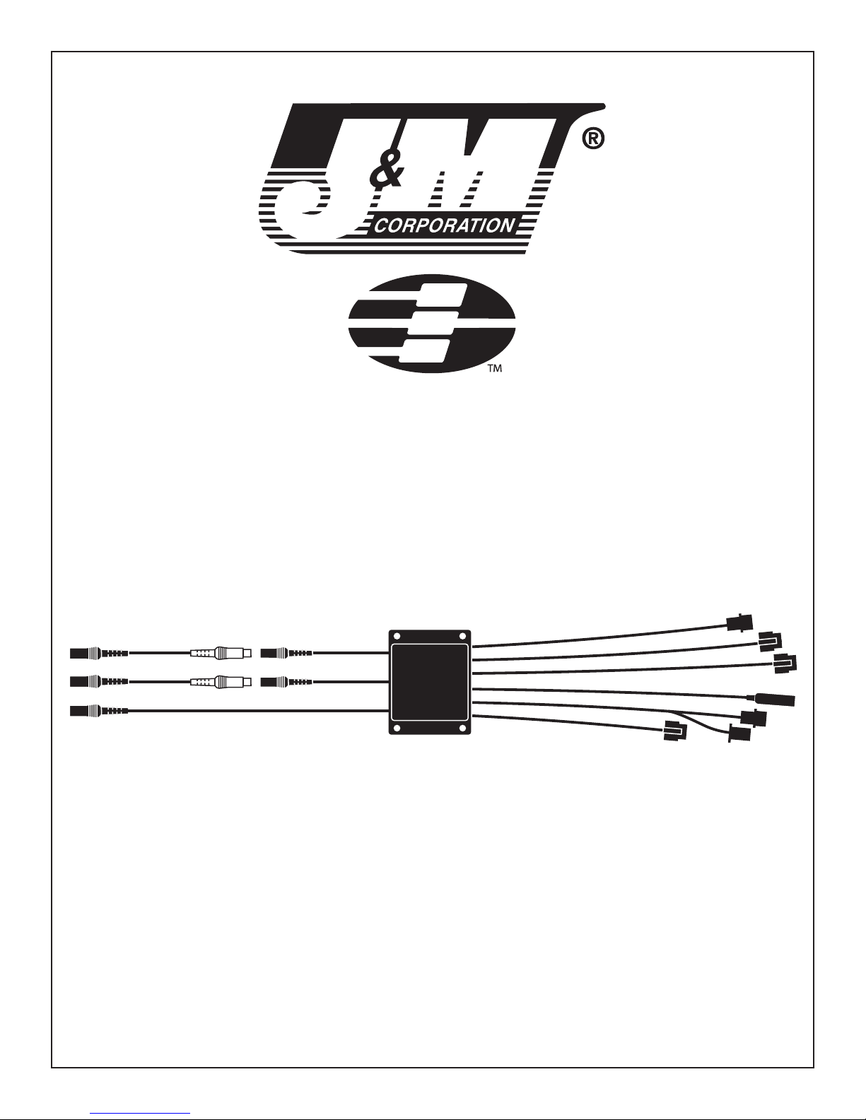
1. Mount the control module inside the front fairing where
desired, taking into consideration the wire lengths of the
different components. Be sure to keep all the associated
cables and wires as far as possible from ignition coils and
wires, voltage regulator rectifiers, and other potential sources
of unwanted noise. Secure the control module at its mounting
location with screws and nuts, double-back tape, or tie straps,
all of which are provided.
2. Mount the handlebar control switch assembly to the
handlebar with the supplied bracket. Run switch cable to the
IntegratrV component and plug in per diagram.
3. Connect the power wire (red) to a switchable power source
or accessory terminal so that the unit is automatically turned
off when the ignition is turned off. Connect the black wire to a
frame ground. If it becomes necessary to replace the fuse use
a 3 amp fuse.
4. Route all other cables where desired and hook them up
according to the wiring diagram.
Auxiliary Audio Input
The IntegratrV provides a cable to connect auxiliary audio players
(such as MP3/ IPOD devices) to the audio input (Level 1).
• Connect the accessory audio device using the connection
auxiliary cable.
• Using the handlebar volume control switch, adjust the audio
to maximum volume.
• Then adjust the audio volume of the accessory audio device to
a level just before distortion.
• Now adjust the volume to a comfortable headset level using
the handlebar rocker volume switch.
Rider / Passenger Intercom
Intercom volume adjustment. To initially set the intercom, pull
out and hold on the intercom volume/sensitivity knob, turn it
all the way clockwise, and release the knob so that it returns to
the inward position. With the knob in the inward position turn
it clockwise to increase the intercom volume. Speak into your
microphone to activate the intercom and continue to adjust the
volume to a comfortable level.
Vox sensitivity adjustment. Pull out and hold the intercom
volume/sensitivity knob to adjust the vox sensitivity. Turning
it counter-clockwise will make it more difficult to activate the
intercom with your voice. Turning it clockwise makes it easier
to voice-activate the intercom function. The idea here is to
turn the sensitivity control knob as far counter-clockwise as
necessary so as to allow the intercom to be activated only
when you or your passenger speak into the microphone.
Once you have adjusted the sensitivity while traveling at
highway speeds, it should not have to be adjusted every time
you ride.
To find the optimum vox sensitivity, make only small
adjustments at a time.
Approximately 3.5 seconds after your intercom conversation
is over, the music will return to both helmet speakers at the
volume previously set.
Note: For maximum enjoyment of the system, it is important
that the helmet headset microphone placement be correct, as
advised in the headset installation instructions. Too much gap
between the mouth and microphone will result in excessive
noise entering the system and imperfect intercom operation
/ VOX switching.
Cellular Telephone or Navigation Systems (GPS)
The IntegratrV provides an input for cellular phone or Navigation
System (GPS). Given the increased emphasis/local legislation
requiring the use of cellular phone headsets while driving a car,
as well as the proliferation of phone models and calling plans
available, J&M is providing a simple connection to the IntegratrV
via the cellular phone headset 3.5 mm jack found on most
phones. If your phone does not have a headset jack, consult
your phone supplier for an accessory headset adapter or with an
optional adapter harness a Navigation System can be connected
to the IntegratrV.
• Consult your cellular phone owners manual to set your
telephone to auto-answer. This will allow you to receive calls
while riding, without the need to touch or manipulate the phone
to receive a call.
• Adjust the volume of the phone audio to be received at a
comfortable level. To do this, use the cellular phone volume
control (you need to receive a real call to do this) before the ride
begins.
• For cellular phones equipped with voice-command dialing,
your helmet headset microphone is continually connected to the
cellular phone. This will enable the rider or passenger to activate
the voice command dialing feature from the phone itself and give
the commands from the helmet mounted mike.
• Once a call is received, the rider and passenger headsets
will connect to the phone via a distinct VOX activated intercom
channel, muting out all lower level communications (music and
FRS radio). Phone conversations are then shared by rider and
passenger. Any audio generated from the phone or voice input
will keep the intercom latched, with a 3.5 second intercom delay
from the last VOX input. If a pause in conversation exceeds 3.5
seconds, lower level audio will return until new VOX input is
received.
• You may need to fine-tune the cell phone volume until you
have established a comfortable volume level while riding.
Manipulation of phone controls while riding is not recommended.
Note: 1 When using a minority of cell phone providers / systems
you may hear a slight buzz in the helmet headset when cellular
phone activation occurs. This buzzing noise is normal and can be
reduced or eliminated by placing the cellular phone as far away
as possible from the IntegratrV.
FRS / GMRS Two-Way Radio
• The IntegratrV provides a port to connect FRS / GMRS radio’s
of various types such as Kenwood FreeTalk™ or Motorola “ T
Series “ with corresponding adapter cables.
Operation
• We recommend reading the owners manual provided with
your FRS / GMRS radio to take full advantage of the features
and benefits.
• Connect the FRS radio cable to the IntegratrV. Turn the FRS
radio “on”.
• We recommend placing the radio on the fairing.
• Adjust the volume of the FRS radio to be received at a
comfortable level. Use the FRS radio volume control to do this
(you need to receive a real transmission to do this) before the
ride begins.
• Incoming FRS radio transmissions will activate the intercom
system, mute the music (Level 1), and will be heard by rider and
passenger. Rider and passenger can discuss what is being heard
from the FRS radio without that conversation be transmitted.
• To transmit, rider must press and hold the PTT button.
• The 3.5 second delay of the intercom system aids two-way
radio conversations, since most users don’t say “over” when their
statements are finished. The 3.5 second delay also provides time
to bridge the natural pause that occurs while listeners determine
the incoming speech has ended, before they respond.
Note: If you receive a cell phone call while riding with the
FRS radio in use, the cell phone will mute all Level 1 & 3
communications. However, if (out of habit) you press the PTT
button while talking on the phone that portion of your phone
conversation could be transmitted over the FRS radio.
Note: The range afforded with the FRS radio will vary depending
upon terrain, weather conditions, outside sources of interference,
etc.
Radar Detector
• Mount your radar detector to the motorcycle and connect it to
the IntegratrV with one of the optional connection cables.
• Radar detectors will momentarily mute all other audio,
momentarily muting all other forms of communication only in the
right speaker of the helmet headset. Therefore, the left speaker
will still be playing whatever audio is being used, but the right
speaker will play the warning tone.
Use of radar detectors may not be approved in all States. Please
consult and observe all local regulations.
Noise and Interference
Motorcycle audio systems by their very nature are noisy. While
we do not guarantee this system to be completely free from
electrical noises and interference, we have taken many steps
to achieve that goal: the power supply system is well filtered,
the unit is shielded in its metal container, and the cables
associated with the unit are shielded.
Most modern day motorcycles have resitor-type spark plugs
installed by the factory. It may be necessary to insure that
resistor-type spark plugs are installed on your motorcycle.
Power requirements: 11-16 volts DC negative ground
Minimum speaker impedance: 32Ω
Typical current draw: 1.5 amps
Thank you for the confidence you have shown in J&M Corporation by
purchasing one of our innovative products.
If you have any question or comments about this product, you may
contact us at USA 1-520-624-7000 Monday thru Friday, 8:00AM
thru 5:00PM Mountain Standard Time.
1415 S. Cherry Avenue
Tucson, AZ 85713 U.S.A.
Tel: (800) 358-0881
Website: http://www.jmcorp.com
E-mail: [email protected]

Other J&M Corporation Stereo System manuals

J&M Corporation STAGE-4 ROKKER XXR Custom User manual

J&M Corporation

J&M Corporation STAGE-4 ROKKER XXR Custom User manual

J&M Corporation JMC ROKKER XXRK-400SPSB-VHL User manual

J&M Corporation

J&M Corporation JMC ROKKER XXRK-400SPSB-VHL User manual

Popular Stereo System manuals by other brands

RCA RS-1247 user guide

RCA

RCA RS-1247 user guide

Sharp XL-S10 Service manual

Sharp

Sharp XL-S10 Service manual

Sony MHC-GNX100, MHC-GNX90, MHC-GNX operating instructions

Sony

Sony MHC-GNX100, MHC-GNX90, MHC-GNX operating instructions

Sony HCD-EX66 Service manual

Sony

Sony HCD-EX66 Service manual

Philips FW 322 Instrucciones de manejo

Philips

Philips FW 322 Instrucciones de manejo

Philips Streamium WACS700 user manual

Philips

Philips Streamium WACS700 user manual

Kenwood HM-982RW instruction manual

Kenwood

Kenwood HM-982RW instruction manual

Philips MC138/25 user manual

Philips

Philips MC138/25 user manual

Philips AZ3021/17 Specifications

Philips

Philips AZ3021/17 Specifications

Panasonic SC-EN33 operating instructions

Panasonic

Panasonic SC-EN33 operating instructions

Philips FW P88 manual

Philips

Philips FW P88 manual

Sony CMT-GS10 operating instructions

Sony

Sony CMT-GS10 operating instructions

NAIM MU-SO quick start guide

NAIM

NAIM MU-SO quick start guide

Sharp XL-MP131 Operation manual

Sharp

Sharp XL-MP131 Operation manual

Philips FW-V28 user manual

Philips

Philips FW-V28 user manual

Sony HCD-SHAKE5 Service manual

Sony

Sony HCD-SHAKE5 Service manual

RCA RS2058 user manual

RCA

RCA RS2058 user manual

RCA RS2635 user manual

RCA

RCA RS2635 user manual

manuals.online logo
manuals.online logoBrands
  • About & Mission
  • Contact us
  • Privacy Policy
  • Terms and Conditions

Copyright 2025 Manuals.Online. All Rights Reserved.