3
Ace Pump Breakdown and Water Seal Replacement
ASSEMBLY
1. Clean and inspect seal bores on mounting frame and seal plate. Bore damage or gouges may prevent proper sealing.
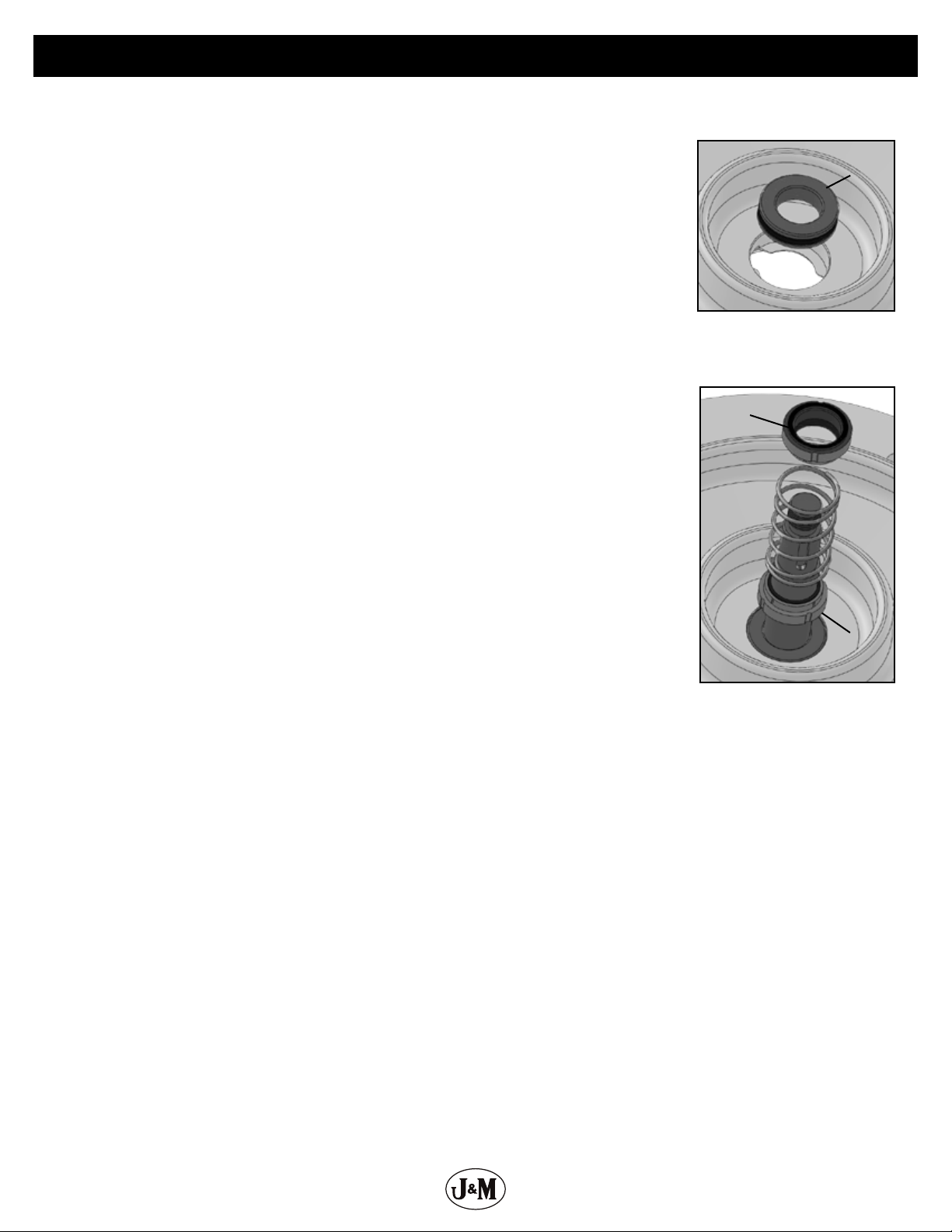
2. Install stationary seal seats:
Important: Avoid touching seal faces by covering with a soft, clean cloth.
Lubrication: Lightly oil O-ring with clean barrier uid to aid installation.
a. Push a seal seat by hand into mounting frame seal bore with grooved side towards bore.
b. Push a seal seat into seal plate seal bore by hand with grooved side towards bore.
3. Press or tap shaft/bearing assembly into mounting frame from rear motor ange.
Note: Use a non-marring hammer and soft wood block to prevent shaft or spline damage.
4. Install rear snap ring into mounting frame bearing bore.
5. Stand mounting frame/shaft assembly on motor mount ange with shaft pointing up.
6. Install rotating seal faces:
Important: Avoid touching seal faces.
Lubrication: Lightly oil rotating assembly bellows and shaft with barrier uid to aid installation.
a. Push rst rotating seal assembly over shaft by hand until black polished face seats against stationary face in mounting frame.
b. Place spring on shaft above rst rotating seal assembly.
c. Push second rotating seal assembly over shaft by hand until metal seal cup seats against
spring. Polished black seal face should be up towards impeller.
7. Install seal plate O-ring over boss on mounting frame. Stretch O-ring over boss – do not roll.
8. Install seal plate and tighten (2) or (4) socket head cap screws to 20 ft-lb (27 N-m).
9. Insert key in keyway and apply anti-seize compound to impeller seat area and key.
10. Install impeller on shaft and apply nut lock to threaded shaft end.
11. Install acorn nut and tighten to 70 ft-lb (95 N-m).
12. Install volute seal O-ring over boss on seal plate. Stretch O-ring over boss – do not roll.
13. Install volute
14. Apply nut lock to (4) volute cap screws, install, and tighten to 20 ft-lb (27 N-m). Allow nut lock to
cure for a minimum of 10 minutes before lling pump.
Note: Place a at washer under volute cap screw at pump discharge port.
15. Apply high speed coupling grease to internal splines of pump shaft.
16. Install O-ring on motor ange boss and position pad over shaft.
17. Install motor aligning shaft splines with pump shaft.
18. Install motor socket head cap screws with washers and tighten to 20 ft-lb (27 N-m).
19. Place pump on a level surface.
20. Remove ll plug on top of seal reservoir.
21. Add supplied barrier uid until level is at top edge of site window.
Caution: Do not overll.
22. Replace ll plug.
23. Add air until gauge reads 25 to 30 psi. An air supply or tank regulated to 30 psi is best.
Caution: Do not overpressurize. Relieve excess air pressure if necessary.
24. Replace air valve cap.
Step 2
Step 6