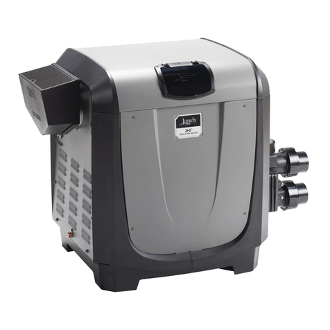
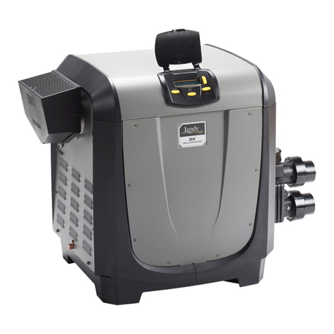
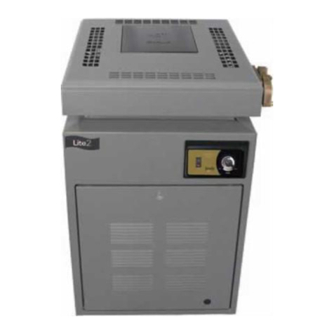
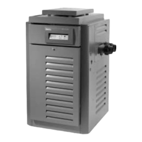
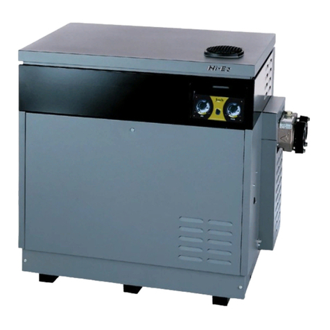
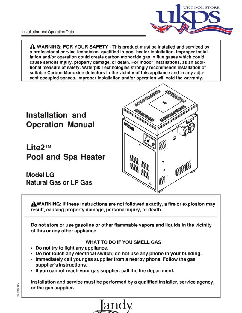
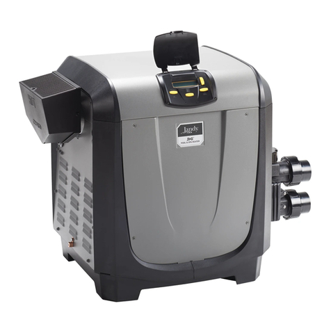
Jandy Laars Lite 2 LG User manual

WARNING
FOR YOUR SAFETY - This product must be installed and serviced by a contractor who is licensed
and qualified in pool equipment by the jurisdiction in which the product will be installed where such
state or local requirements exists. In the event no such state or local requirement exists, the installer
or maintainer must be a professional with sufficient experience in pool equipment installation and
maintenance so that all of the instructions in this manual can be followed exactly. Before installing
this product, read and follow all warning notices and instructions that accompany this product.
Failure to follow warning notices and instructions may result in property damage, personal injury, or
death. Improper installation and/or operation can create carbon monoxide gas and flue gases which
can cause serious injury, property damage, or death. For indoor installations, as an additional mea-
sure of safety, Zodiac Pool Systems, Inc. strongly recommends installation of suitable Carbon
Monoxide detectors in the vicinity of this appliance and in any adjacent occupied spaces. Improper
installation and/or operation will void the warranty.
H0208700G
Installation and Operation Data
Installation and
Operation Manual
Lite 2™
Model LG
Pool and Spa Heater
Natural Gas or LPG Gas
WARNING
Read this manual in its entirety. If these instructions are not followed exactly, a fire or
explosion may result, causing property damage, personal injury, or death.
The GAS SAFETY (INSTALLATION AND USE) REGULATIONS 1998 as amended,
place statutory requirements on gas users.
This heater is certified to European requirements for use only as a swimming
pool or spa heater. The heater must not be used for any other purpose and must
be installed and serviced by a qualified professional. The heater must be
operated strictly in accordance with the user's instructions and applicable laws.
If the heater is installed in a room, it must be separated from a living space, and
adequate air supply and ventilation must be provided and maintained.
Do not store or use gasoline or other flammable vapors and liquids in the vicinity
of this or any other appliance.
H0209800D
TEMPERATURE
CONTROL
POOL


TABLE OF CONTENTS
SECTION 1.
General Information
1A. Introduction ................................................... 1
1B. Description ................................................... 1
1C. Warranty....................................................... 3
SECTION 2.
Installation Instructions
2A. Statutory Information .................................... 3
2B. General Installation Requirements ............... 3
2C. Reversible Water Connections ..................... 3
2D. Site Location ................................................ 6
2D-1. Indoor Installation ......................................... 6
2D-2. Outdoor Installation ...................................... 7
2D-3. Flooring - Typical Installation ....................... 7
2E. Combustion and Ventilation Air Supply ........ 8
2F. Flue Specifications ....................................... 8
2F-1. Outdoor Installation ...................................... 8
2F-2. Indoor Installation ......................................... 8
2F-3. Flue System (Indoor) .................................... 8
2G. Gas Supply and Piping ................................. 9
2H. Electrical Wiring ........................................... 9
2H-1. General Information ..................................... 9
2H-2. Auxiliary Tim Clock Wiring ........................... 9
2I. Water Piping .............................................. 10
2I-1. General Information ................................... 10
2I-2. Automatic Chlorinators (Chemical
Feeders) ..................................................... 10
2J. Pressure Relief Valve ................................. 11
2K. Pressure Switch Adjustment ....................... 11
2L. Temperature Rise ....................................... 11
SECTION 3.
Operating Instructions
3A. Start-Up Procedure .................................... 12
3B. Temperature Control .................................. 13
3C. Lighting and Shutdown ............................... 13
3C-1. Lighting the Heater ..................................... 13
3C-2. Relighting the Heater .................................. 14
3C-3. Shut-Down Procedure ................................ 14
3C-4. Putting the Heater in Operation
(Commissioning) ........................................ 14
3C-5. Filter Pump Operation ................................ 15
3D. Inlet/Outlet Temperatures .......................... 15
3E. Seasonal Care ............................................ 15
3E-1. Spring and Fall Operation .......................... 15
3E-2. Winterizing ................................................. 15
3F. Water Chemistry ........................................ 16
3F-1. For Pool ...................................................... 16
3F-2. For Spa ....................................................... 16
3F-3. Corrosion .................................................... 17
3F-4. Testing........................................................ 17
3G. Swimming Pool Energy Savings Tips ........ 17
3H. Periodic Inspection (Routine Service) ........ 17
SECTION 4.
Maintenance
4A. Gas Pressure Tests .................................... 18
4B. Pressure Switch Adjustment ....................... 19
4C. Replacing the Gas Valve ............................ 19
4D. Removal of Gas Burners ............................ 20
4E. Heat Exchanger .......................................... 21
4E-1. Periodic Inspection of Heat Exchanger
Water Passages ......................................... 21
4E-2. Cleaning the Heat Exchanger .................... 22
4F. Automatic Flow Control Valve .................... 23
SECTION 5.
Field Installation for External Flue
Terminal or Draught Divertor
5A. General Information ................................... 23
5B. Installation Procedures ............................... 23
SECTION 6.
Parts List for Lite 2,
Model LG Heater
6A. General Information ................................... 25
6B. Parts List .................................................... 26


Page1LITE 2 MODEL LG POOL AND SPA HEATER
SECTION 1.
General Information
1A. Introduction
This manual provides installation, operation, and
owner'sinstructionsfortheLite 2 Model LG millivolt
pool and spa heater, sizes 125 through 400. The Lite
2 range of heaters has been tested and certified by
British Gas to the latest draught of European Stan-
dard, PREN656, and the appliance is manufactured in
accordance with all required quality procedures
(Certificate N:BG/EC-87/95/46/M7, PI number
87AQ46). LG performance characteristics are listed
in Table 1. General data for the model LG is listed in
Table 2. The basic configuration of the LG heater is
shown in Figure 1.
1B. Description
The model LG is a compact, high performance
pool heater. The heater converts heat from the pilot
into electricity which operates the controls.
LGSize(inBTUInput)
125BTU 175 BTU 250BTU 325 BTU 400BTU
Nat. Nat. Nat. Nat. Nat.
Gas LPG Gas LPG Gas LPG Gas LPG Gas LPG
Heat Input Gross (kW) 36.6 36.6 51.3 51.3 79.6 75.0 103.4 97.4 117.2 117.2
Heat Input Net (kW) 33.0 33.7 46.2 47.2 71.7 69.0 93.2 89.6 105.6 107.8
Heat Output (kW) 28.4 28.4 39.7 39.7 56.8 53.5 73.8 69.5 90.8 90.8
Burner Pressure (mbar) 10 28-30 10 28-30 10 28-30 10 28-30 10 28-30
Gas Rate (m3/h) 3.5 ___ 4.9 ___ 7___ 9.1 ___ 11.2 ___
Gas Rate (m3/h) G30 ___ 1.05 ___ 1.48 ___ 2.3 ___ 2.99 ___ 3.47
1.38 1.93 2.99 3.89 4.52
Flue Gas Volume
4.5% C02, 120C (I/sec) 32.1 ___ 44.9 ___ 64.1 ___ 83.9 ___ 102.8 ___
Flue Gas Volume
5.5% C02, 135C (I/sec)
G30 ___ 32.3 ___ 45.3 ___ 70.3 ___ 91.4 ___ 106.4
G31 31.8 44.5 69.1 89.7 104.2
Injector Diameter (mm (2.26) (1.4) (2.26) (1.4) (2.26) (1.4) (2.26) (1.4) (2.26) (1.4)
and marking) Marked Marked Marked Marked Marked Marked Marked Marked Marked Marked
43 54 43 54 43 54 43 54 43 54
Appliance Category
Natural Gas I2H
LPG I3+
Inlet Pressure(mbar)
Natural Gas 20
LPG G30 @ 28-30 mbar
G31 @ 37 mbar
Note:
The above LPG heat inputs apply up to an altitude of 600m. Above this altitude, de-rate the heat input by 4% for every
300m.
Table 1. LG Performance Specifications
G31

Page2
FlueDimensions
FlueDiameter(F) Width (W) Outdoor(External Terminal) IndoorDraughtDivertor
Size mm mm A mm B mm A mm B mm
125 125 381 197 358 197 455
175 150 457 234 370 235 630
250 175 572 290 476 292 635
325 200 679 346 457 345 635
400 225 849 410 527 406 660
LG Size
125 175 250 325 400
Water Capacity (L) 0.81 0.95 1.16 1.35 1.57
Minimum Water Flow (l/min) 75.7 75.7 94.6 113.6 113.6
Maximum Static Head (bar) 5.1 5.1 5.1 5.1 5.1
Maximum Outlet Temp (C) 40 40 40 40 40
Dry Weight (kg) 84 91 103 114 128
Gas Connection 3/4 in Bsp 3/4 in Bsp 3/4 in Bsp 3/4 in Bsp 3/4 in Bsp
(Rc 3/4) (Rc 3/4) (Rc 3/4) (Rc 3/4) (Rc 3/4)
Water Inlet Connection 2 in Bsp 2 in Bsp 2 in Bsp 2 in Bsp 2 in Bsp
(Rc 2) (Rc 2) (Rc 2) (Rc 2) (Rc 2)
Water Outlet Connection 2 in Bsp 2 in Bsp 2 in Bsp 2 in Bsp 2 in Bsp
(Rc 2) (Rc 2) (Rc 2) (Rc 2) (Rc 2)
Table 2. Model LG General Data
Figure 1. General Configuration
LaarsLite 2
FLUE TERMINAL / DRAFT DIVERTOR

Page3LITE 2 MODEL LG POOL AND SPA HEATER
WARNING
Do not connect the heater to any external
source of electricity. The Jandy Lite 2 Model
LG heater has a built in thermoelectric
generator. It provides a completely self-
contained electrical system. Any attempt to
make electrical connections to an external
source will damage the heater, and could be
dangerous.
The heater can be installed indoors (using the
draught divertor and a suitable flue system) or out-
doors (using a flue system or with the outdoor flue
terminal assembly, which is available as an optional
extra).
Zodiac Pool Systems, Inc., specifically designs
this appliance to heat fresh water swimming pools
and spas. Do not use it as a heating boiler or general
service water heater. For special applications, consult
your Jandy dealer.
1C. Warranty
The LG heater is sold with a limited factory
warranty. A copy of the warranty is shown on the
back cover of this manual.
The warranty does not cover damage caused by
improper installation, or field modification, or to the
heat exchanger by corrosive water.
SECTION 2.
InstallationInstructions
2A. Statutory Information
It is the law that all gas appliances are to be
installed only by competent persons (e.g., members of
the Confederation of Registered Gas Installers
[CORGI]) in accordance with the Gas Safety (Instal-
lation and Use) Regulations, 1994. Failure to install
appliances correctly could lead to prosecution.
The LG heater, as supplied, has been tested and
certified by British Gas to PREN656 for use with
natural and LPG gases. LG heaters are only permit-
ted to be installed in the open air or in a room which
is separated from living rooms and provided with
appropriateventilation directlyto theoutside.
WARNING
The LG heater is certified to European
requirements for use only as a swimming pool
or spa heater. The LG heater must not be used
for any other purpose and must be installed
and serviced by a qualified professional. The
LG heater must be operated strictly in
accordance with the manufacturer's
instructions. If the LG heater is installed in a
room, adequate air supply and ventilation must
be provided and maintained. Never store any
materials within the area of the heater or
ventilationopenings.
It is important that no external control devices
(e.g., flue dampers, economizers, etc.) be directly
connected to the LG heater unless covered by these
installation and servicing instructions or otherwise
recommended in writing by Zodiac Pool Systems, Inc.
If in doubt please ask. Any direct connection of a
control device not approved by Zodiac Pool Systems,
Inc., could invalidate the British Gas certification, the
normal LG heater warranty, and could also violate
applicable gas safety regulations.
2B. General Installation Requirements
The LG heater must be installed by competent
persons (e.g., CORGI member). The LG heater must
be installed in accordance with the relevant require-
ments of the Gas Safety Regulations, current I.E.E.
Regulations, Model Water Bylaws, local Water
Authority Bylaws, and any relevant requirements of
local gas region, local authority, and relevant British
Standard Codes of Practice and Building Regulations.
Table 3 lists regulations for small and large pipe
installations.
All gas-fired products require correct installation
to assure safe operation. The requirements for heaters
includethefollowing:
1. Appropriate site location (clearances)
2. Non combustible surface
3. Sufficient combustion air and ventilation air
4. Adequate ventingof combustion products
5. Adequate waterflow
6. Properly sized gas pipe
7. Regularmaintenance
2C. Reversible Water Connections
Zodiac Pool Systems, Inc., ships the LG heater
with the water connections on the right side. It could

Page4
Small Pipes Large Pipes
British Gas Publications:
IM2 Purging Procedures of Non-Domestic
Gas Installations
IM5 Soundness Testing Procedures for
Industrial and Commercial Gas
Installations
BS.6891 Installation of Low Pressure IM11 Flues for Commercial and Industrial
Pipework Gas Fired Boilers and Air Heaters
IM16 Guidance notes on the Installation
of Gas Pipework, Boosters, and
Compressors in Customer's Premises
Equal to or Greater than 25 mm (non-
domestic)
BS.6644 Installation of Gas Fired Hot Water
Boilers 60kW to 2MW.
CP341 Water Supply
Model Water Bylaws
Note: Manufacturer's notes must not be taken in any way as overriding statutory obligations.
Table 3. Pipe Installation Regulations
be necessary, or helpful, to switch the connections to
the left side to improve access for service.
To make this change, a trained service techni-
cian should reverse the heat exchanger before
beginningtheinstallation.
Follow these step-by-step instructions and use
theaccompanyingillustrations.
1. Removeheaterdoor.
2. If there is a flue terminal or draught diverter
(indoor) on top of the heater, remove it.
3. Removeallhex-headscrewsfasteningthetop and
lift the top assembly straight up (see Figure 2).
4. Removethescrewholdingtherainshieldtotherear
oftheheater.Removetherainshieldassemblyand
set it aside.
5. Remove screws that fasten the gap closures and
put them aside. Remove gap closures.
6. Remove bracket under the front header, which
holds capillary of the manual reset thermostat
(see Figure 2).
7. Remove the two heat exchanger end baffles
from inside the flue collector. To remove the
baffles, first remove the screws securing them
to the top of the front and rear combustion
chamber panels.
8. Remove the screws securing the two flue
collector holddown clamps and remove the
clamps (see Figure 3). Remove flue collector.
9. Remove the three jacket/plug grommets and
drain plugs (see Figure 2). One is located under
the water connections on the right side of the
heater. The other two are on the left side of the
heater. Gently pry the button plug from the
heater jacket located on the right side of the
heater.
10. Tag and disconnect the white wire on the pres-
sure switch (PS) and the white wire at the
terminalblock.
11. Remove plastic tie wraps and pull the white
wires out of the front compartment through the
vestibule cover and coil them on the heat
exchanger.

Page5LITE 2 MODEL LG POOL AND SPA HEATER
12. Unscrew the nut on the brass compression
fitting securing the pressure switch to the
header. Remove tube from header and gently
bend it out of the way.
13. Loosen the screw securing the temperature
sensing bulb retainer bracket. Slide the retainer
bracket off the bulb flange and remove the bulb
from the header (see Figure 4). Remove the
white pressure retainer clip from the vestibule
panel (allow pressure switch to float). Pull
pressure switch tube through vestibule cover hole
into the front compartment,then pull thermostat
bulbassembly through samehole.
Figure 3. Flue collector holddown brackets.
Figure 4. Temperature sensing bulb.
Caution
It may be necessary to have help lifting the
heat exchanger out and replacing it.
14. Lift out the heat exchanger assembly and set it
aside. Make sure that the insulation strips on the
tops of the combustion chamber sides remain in
place. Re-install heat exchanger 180 degrees
fromitsoriginal position (header left).
15. Remove the plastic bushing from the hole on the
right side of vestibule cover. Re-install it in the
hole on the left vestibule cover.
Figure 2. Heat exchanger reversal.
GROMMETS
BUTTON
PLUG
GROMMET
END
BAFFLES
CLAMP
IN/OUT HEADER
BRACKET

Page6
sure to push the baffles against the flue collector
sides,closing allgaps.
24. Drillcapillaryhole(20mmdiameter)symmetri-
cally opposite to one on right hand side of jacket.
Remove the grommet from the hole on the right
side of the heater and place it in the new hole.
Re-route capillary and re-install the bracket.
25. Attach the flue collector holddown clamps to the
clips located under the two center header bolts.
26. Replace the gap closures and tighten the screws
securely.
27. Double-check to make sure the wiring is not
pinched against sharp edges, or resting on the
fluecollectorassembly.
28. Re-install rainshield assembly and replace the
screw securing it to the rear of the jacket.
29. Replace the top assembly. Make sure the tabs
are outside the heater jacket. Fasten the top
assembly with the hex-head screws.
30. Install plastic tie wraps on wiring in the front
compartment(vestibule).
31. Install heater door.
32. Reinstall the flue terminal or draught diverter, if
one was removed.
2D. Site Location
2D-1. Indoor Installation
The Lite 2 LG )heater is designed and certified
forindoor installationonly whenequipped witha
draught divertor and flue system. Check the literature
or rating plate for the correct LG Lite 2 draught
divertor part numbers. Install the draught divertor
withoutmodification.
WARNING
Improper installation or maintenance can
cause nausea or asphyxiation from carbon
monoxide in flue gases which could result in
severe injury, property damage, or death.
Place the heater in an area where leakage of the
heater or connections will not result in damage to the
area around the heater or to the structure. If this is
not possible, provide a suitable drain pan to catch and
divert any leakage. The pan must not restrict air flow.
16. Re-route the thermostat bulb assembly, then the
pressure switch tube through the hole in the left
side of the vestibule cover.
17. Re-install the temperature sensing bulb in the
header, and fasten it with the retainer bracket
and screw.
18. Re-install the nut, at end of pressure switch line,
into the compression fitting in the header.
19. Route the white wiring beside the heat exchanger
and down to the original location. Be careful to
keep the wires away from the flue collector.
Secure white wires to the pressure switch tube
with tie straps.
20. Connect the white wire labeled PS to the pres-
sure switch and the other white wire to its
original location at the terminal block (see
Figure 5).
21. Replace jacket/plugs grommets, and re-install the
drain plugs. Tighten securely. Replace the button
plug into the remaining hole in the jacket.
22. Install the flue collector assembly. Be sure the
bottom lips are inside the grooves on the front
and rear combustion chamber panels and are not
pinching any wires.
23. Use the screws removed earlier to replace the
two heat exchanger end baffles. Mount one to
the top of the rear combustion chamber panel
and the other to the top of the front combustion
chamber panel. Before tightening the screws, be
Figure 5. Terminal block.
Terminal
Block

Page7LITE 2 MODEL LG POOL AND SPA HEATER
Table 4. Minimum Heater Clearances From
Combustible Surfaces
Minimum Clearance
Side of Heater mm
Rear 150
Piping 300
Blank 150
Front 450
Above Heater 1120
Figure 6. Outdoor heater location.
1.12 meters above the top of the heater. The area
under the overhang must be open on three sides. This
stopscombustion gasesfrom beingdiverted intoliving
areas through doors, windows, or gravity inlets.
Protect the heater from direct water drainage.
Do not place the heater with the top of the casing
(flue outlet) within 2 meters of any opening into a
building (see Figure 6).
Due to the chance of down-draughts caused
by high wind conditions, place the heater at least 1
meter from vertical surfaces, such as nearby buildings
and walls. The addition of an outdoor flue terminal
assembly which is optional, may ease the problem.
2D-3. Flooring - Typical Installation
Except as described below, place all heaters on a
noncombustible surface. A heater can be placed on a
combustible floor by placing a non-combustible base
under the heater, available from Zodiac Pool Systems,
Inc. See the heater rating plate for the base part
number. Do not place the heater directly on carpeting
Place the heater to provide adequate clearance
on all sides for inspection, (see Table 4, Page 7)
service and to provide adequate air circulation for
proper operation. Make sure that the location of the
heater complies with the requirements detailed in
these instructions for ventilation, clearances, and flue
system.
2D-2. Outdoor Installation
Place the heater in an area where leakage of the
heater or connections will not result in damage to the
area around the heater or to the structure. If this is not
possible, provide a suitable drain pan to catch and
divert any leakage. The pan must not restrict air flow.
Place the heater in an open, unroofed area, and
keep the clearances detailed in Table 4.
Do not place the heater in an area where leaves
or other combustible materials can gather around the
base or on top of the heater.
Do not place the heater close to sprinklers that
could spray water on it. Excess water could damage
the heater.
The heater must be installed at least 1.52 meters
from the edge of the pool or spa unless separated
from the pool or spa by a solid fence, wall, or other
permanent barrier. If you are placing the heater under
an overhang, there must be a minimum clearance of
Figure 7. Non-combustible platform.
Table 5. Ventilation Requirements
Position of Air Vent Areas
Air Vents (Air Direct From Outside)
High Level 270 cm2plus 2.25 cm2 per kW
in excess of 60 kW total rated
input
Low Level 540 cm2plus 4.5 cm2 per kW
in excess of 60 kW total rated
input

Page8
without placing a base or platform between the
carpeting and the heater. The base or platform may
be made of hollow masonry no less than 102 millime-
ters (mm) thick, covered with sheet metal at 24 gauge
thick. The masonry must be laid with ends unsealed
and joints matched to let air flow from side to side and
through the masonry (see Figure 7).
2E. CombustionandVentilationAirSupply
All indoor installations must have uninterrupted
openings to outside air for combustion and ventilation.
Table 5 shows the net free opening areas required at
both ceiling and floor for the different heater sizes.
2F. Flue Specifications
2F-1. Outdoor Installation
The LG heater is ready for installation outdoors.
Make sure the installation instructions are followed. If
the installation is in an area that has draught condi-
tions, an outdoor flue terminal assembly, which is
optional, may be obtained from Zodiac Pool Systems,
Inc.
2F-2. Indoor Installation
The LG heater can be installed indoors using the
draught divertor available from Zodiac Pool Systems,
Inc., and a flue system complying with the National
and European Standards in addition to the Building
Regulations (see Section 2).
2F-3. Flue System (Indoor)
Connect the draught divertor to a flue system of
at least the same diameter, and end at least 0.61
meters above the highest point of the roof or other
object that is within 3 meters of the vent. Install a
certified terminal which allows a full equivalent
opening for flue products (see Figure 8). There must
be at least 600mm of vertical flue above the
drafthood. Bends in the flue should not exceed 45° to
the vertical.
To make sure the heater operates safely and
satisfactorily, the flue system must be able to com-
pletely remove combustion products at all times. The
number of bends and lengths of horizontal flue pipe
used should be kept to a minimum in order to reduce
gas flow resistance.
Compliancewiththerecommendationsmadein
BS.6644, British Gas publication IM11, Flues for
Commercial and Industrial Gas Fired Boilers and Air
Heaters, and the 1956 Clean Air Act Memorandum,
3rd Edition, should be strictly observed where appli-
cable.The flue design should avoid the formation of
excessive quantities of condensate. For this reason, it
is recommended that all flues be insulated and lined.
For brick or similar structures, a stainless steel rigid or
flexible flue liner (Grade 304/316) may be used in
conjunctionwitha50 mm (minimum) thick layer or
vermiculite or perlite granules between the liner and
the inner skin of the chimney body.
Figure 8. Flue system.

Page9LITE 2 MODEL LG POOL AND SPA HEATER
2H. ElectricalWiring
2H-1. General Information
WARNING
Do not connect the heater to any external
source of electricity. The Jandy Lite 2 Model
LG heater has a built-in thermoelectric
generator. It provides a completely self-
contained electrical system. Any attempt to
make electrical connections to an external
source will damage the heater, and could be
dangerous.
Liners should be sealed at both top and bottom.
Drainage points should be provided at the bottom of
all vertical flue sections. Drain pipes should be:
1. No less than 25 mm inside diameter.
2. Made from acid condensate resistant material
(e.g., stainless steel).
3. Positioned so that pipe runs and discharge
points are not subject to the effects of frost
and flue gases cannot leak into the boiler
room.
2G. Gas Supply and Piping
If there is any doubt regarding the capacity of
any existing service pipes or the size required for new
service pipes then the advice of the gas supplier
should be requested. Installation pipework should be
fitted and tested for gas soundness in accordance
with Table 3.
Zodiac Pool Systems, Inc., recommends the gas
inlet pipe sizes listed in Table 6.
Provide and fit a gas service cock and union
external to the heater for servicing purposes (see
Figure 9).
Before operating the heater, test for gas sound-
ness in accordance with the publications listed in
Table 3. Do not use a naked flame. If the supply gas
pressure is less than required, check for undersized
pipe between the tank and the heater, a restrictive
fitting, or an empty tank.
Table 6. Pipe Size Requirements
Distance from Gas Meter
Model 0-15 m 15-30 m 30-60 m
Size mm mm mm
125 22 28 28
175 28 28 35
250 28 35 35
325 35 35 42
400 35 42 42
Figure 10 shows a typical wiring diagram for the
LG heater. The heater wiring diagram can also be
found on the inside of the heater.
2H-2. Auxiliary Time Clock Wiring
If a time clock is to be installed to control the
filter pump operation, we recommend (for the reason
of efficiency) the clock have its own low voltage
(Fireman's) switch to turn off the heater before
turning off the pump. The switch should shut off the
Figure 9. Fitting a gas service cock. Figure 10. Typical wiring diagram.
Gas Cock
Union
Lite 2 LG
HeaterWiringDiagram If any of the original wire as supplied with
the heater must be replaced, appliance
wiring material rated for 105°C must be
used. Where marked______, appliance
wiring material rated for 200°C must be
used.
ManualReset
Thermostat HighLimit
Switch HighLimit
Switch
Temperature
Control
On/Off
Pressure
Switch
Fireman
Switch
Connection
Fusible
Link
Piezo
Ignitor
Thermocouple
A=Black
B=White
C=Yellow
D=Red
CC
B
B
B
A
B
D
TH/PP PP
TH
B
A
BA
A
A

Page10
heater about 15 minutes before the filter pump shuts
off. To install a time clock auxiliary switch into the
heater wiring, follow these steps (see Figure 11):
1. Remove theservice door.
2. Removethefactory-installedwirebetween
terminals 1 and 2 on the terminal block
(see Figure 5).
3. Connect the wires from the time clock
auxiliary switch to the two terminals. Use 14
gauge copper wire with insulation at least 1.2
mm thick, and a temperature rating of 105
degrees Celsius (°C) or greater. The length of
the wire between the heater and the time
clock should not exceed 4.57 m. The contact
points of the time clock switch should be
silver, or a low resistance alloy.
2I. Water Piping
2I-1. General Information
High temperature plastic piping (CPVC Sched-
ule 80) may be connected directly to the inlet/outlet
header providing that the controls keep the filter pump
running at least 15 minutes after the heater is turned
off. Plastic materials may be used in pipes, fittings,
grids, and other elements of the filter system if accept-
able by the authorities having jurisdiction (see Figure
12). If unacceptable, use a metal heat sink pipe
between the filter and the heater (see Figure 15).
Install a check valve if there is any chance of
back siphoning when the pump stops (see Figure 13).
Do not install any other valve or variable restriction in
the piping between the heater outlet and the pool,
unless it is necessary to increase back pressure, or is
being used as a diverter valve.
The heater has 50 mm universal header cou-
plings. You can connect threaded 50 mm iron or
copper pipe or unthreaded 38 mm iron or copper pipe
without an adapter. CPVC pipe can be used by first
installing the CPVC nipples, provided with this heater,
into the cast iron fittings (see Figure 12).
2I-2. Automatic Chlorinators (Chemical
Feeders)
Anyexcessiveconcentrationofchlorine in the
pool heater can be very destructive. Heater damage
caused by an excessive concentration of chlorine is not
covered by the warranty. All chlorinators should be
downstream of the heater.
Equip the chlorinator with an anti-siphoning
(back flow) device so that chlorine will not siphon
into the heater after the pump is shut off.
Wire the chlorinator so it cannot operate unless
the filter pump is running. If the chlorinator has an
independent clock control, be sure the filter and
chlorinatorclocksare synchronized.
Figure 11. Time clock wiring.
Figure 12. Piping connections.
TO LIMIT SWITCHES TO LIMIT SWITCHES
FIELD PROVIDED WIRING
LOW VOLTAGE
SWITCH
TIME CLOCK
FUSIBLE LINK FUSIBLE LINK
WHITE
WHITE
FACTORY
INSTALLED
WIRE
WHITE
WHITE
HEATER WIRING
BEFORE MODIFICATION
MODIFIED HEATER
WIRING WITH TIME
CLOCK INSTALLATION
METHOD FOR INSTALLING
50 MM THREADED PIPE
CPVC
NIPPLE PROVIDED

Page11LITE 2 MODEL LG POOL AND SPA HEATER
If the chlorinator is equipped with its own pump,
install it so that it introduces the chlorine downstream
from the heater, and, if possible, below the level of the
heater outlet fitting.
2J. Pressure Relief Valve
A pressure relief valve is not furnished with
the Lite 2 heater. Local plumbing codes may
requireit.
To install a pressure relief valve:
1. Remove the 19 mm brass plug on top of the
header and screw in the valve (seeFigure 14).
2. The setting of the valve should be at or below
the lowest working pressure of any compo-
nent in the filter system.
2K. Pressure Switch Adjustment
The pressure switch is pre-set at the factory for
normal pool installations. Do not adjust the pressure
switchunlesstheinstallationinvolvesspecialcondi-
tions such as:
From
Skimmer FromMain
Drain
Balancing
Valves
Filter Heater
Pump
Check
Valve
To
Pool
Manualby-passisused
onlywhenfiltrationrate
normallyexceeds
125gallonsperminute.
Heater
Filter Pump
MainPool
Return
MainPool
Skimmer
Main
Drain
Spa
Balancingvalvesfor
skimmeranddrain.
Three-way
changeover
valves
Figure 13. Typical installation. 1. The top of the heater is installed 1 m or more
below the surface of the pool.
2. If any part of the filter system is 1 m or more
above the top of the heater jacket.
NOTE: Do not make the pressure switch
adjustment if the heater is installed more than 4.6 m
below or 1.9 m above the pool surface. Consult
Zodiac Pool Systems, Inc., for recommendations.
On some installations, the piping from the heater
to the pool is very short. The back pressure could be
too low to trigger the pressure switch. If this happens,
it may be necessary to install a directional fitting, or
elbows, where the return line enters the pool. This will
increase back pressure enough for the heater to
operate properly.
2L. Temperature Rise
When the installation is complete, the installer
should then take a temperature rise. Use the figures in
Table 7 to verify proper water flow through the heater.
Figure 14. Thermometer and pressure relief valve
location.
THERMOMETER
(-29°C TO 52°C)
PRESSURERELIEF
VALVE
Anautomatic,built-inbypass valvemaintains
proper flow through the heater at flow rates less than
7.9 liters per second (l/s). If the system filter-flow
rate exceeds 7.9 l/s, a manual bypass valve is re-
quired. Figure 15 shows a manual bypass valve
installed between the heater inlet and outlet. To set
the bypass valve, follow this procedure:
Temperature Rise Minimum
Minimum Maximum Flow Rate
Size °C°C l/s
125 15 20 1.5
175 18 24 1.5
250 18 24 1.9
325 16 21 2.3
400 17 22 2.3
Table 7. Temperature Rise And Minimum Flow Rates
TEMP AND PRESSURE FITTING
(PETE'S PLUG)

Page12
SECTION 3.
OperatingInstructions
3A. Start-Up Procedure
Full lighting and shutdown instructions are
found on the label attached inside the service door of
the heater and in the user's instructions.
WARNING
Flue pipes, draught divertors, hoods, tops,
and water fittings get hot! These surfaces can
cause serious burns. Do not touch these
surfaces when the heater is operating. For
external installations, the addition of an out-
door flue terminal assembly will reduce the
temperature on the top.
WARNING
Keep all objects off the top of the heater.
Blocking air flow could cause a safety hazard,
damage to the heater, and may void the
warranty.
WARNING
LP Models: To avoid possible injury, fire and
explosion, read and follow these precautions
and all instructions on this heater before
lighting the pilot. This heater uses LP gas
which is heavier than air and will remain at
ground level if there is a leak. Before lighting,
sniff at ground level. If you smell gas, follow
these rules:
1. DO NOT light matches. DO NOT turn
electric lights or switches on or off in area.
DO NOT use an electric fan to remove the
gas from area.
2. Shut off gas at LP tank and gas service
cock.
3. Telephone gas company for instructions.
Give your name, address and phone
number.
If your LP tank runs out of fuel, turn off gas at
the heater. After the tank is re-filled, the heater
must be relit in accordance with the
instructions found on the inside of the door.
DO NOT attempt repairs on the gas control or
heater. Tampering is dangerous and voids all
warranties.
1. Clean the pool filter.
2. With the filter pump off, remove the drain
plug. The plug is found on the right side of
the heater.
3. Replace the drain plug with a thermometer
inserted through a temperature and pressure
fitting (Pete's Plug) (see Figure 14).
4. If there is a manual bypass valve installed,
close it.
5. Make sure the heater is off by moving the
rocker switch to the OFF position.
6. Start the filter pump and wait 3 minutes.
7. Record the thermometer reading (this repre-
sents pool water temperature).
8. Turn the heater on following the lighting and
shutdown instructions found on the inside of
thecontrol compartment.
9. Let the heater run for at least 5 minutes
beforerecordingthenewthermometer
reading.
10.If the temperature reading is outside the
minimum/maximumnumbersshowninTable
7, gradually open the manual bypass valve
until the temperature rise is obtained (the
temperature rise is the difference between
the temperature reading with the heater off
and the temperature readings with the
heater running for several minutes.
11.Be sure the thermometer reading remains
steady for at least 3 minutes.
Figure 15. Heater piping.
Optional
CheckValve
Manual
By-Pass
Valve Plastic
Pipe
NOTE:When using metal
pipeasheatsink,join
metalandPVC/CPVC,
usingmetalmaleand
PVC/CPVCfemale
connection.

Page13LITE 2 MODEL LG POOL AND SPA HEATER
3C. Lighting and Shutdown
3C-1. Lighting the Heater
Fulllightingandshutdowninstructionscanalso
be found attached to the wall inside the control
compartment door.
1. Remove the service door on the front of the
heater.
2. Press down and release the red button
marked “O” on the gas control valve (see
Figure17).
3. Turn the rocker switch to OFF and turn the
temperature control to its lowest setting.
4. Make sure that the manual gas cock is
open.
5. Push in the white button on the gas control
and keep it fully depressed (see Figure 17).
WARNING
Natural Gas Models: To avoid possible
injury, fire and explosion, read and follow
these precautions and all instructions on this
heater before lighting the pilot. If you smell
gas, follow these rules:
1. DO NOT light matches. DO NOT turn
electric lights or switches on or off in area.
DO NOT use an electric fan to remove the
gas from area.
2. Shut off gas at gas service cock.
3. Telephone gas company for instructions.
Give your name, address and phone
number.
DO NOT attempt repairs on the gas control or
heater. Tampering is dangerous and voids all
warranties.
When lighting or relighting the pilot, always
turn the temperature control to its lowest setting. Turn
the rocker switch to OFF.
With any new pool or spa installation, run the
filter pump with the heater off long enough to com-
pletely clean the water. This removes any installation
residue from the water. Clean the filter at the end of
this operation before starting the heater. When raising
the temperature of a cold pool, remove all time clock
settings. This lets the filter system and heater operate
continuously until the water reaches the temperature
setting on the thermostat. When that happens, the
heater will automatically shut off, but the filter pump
willkeeprunning.
3B. Temperature Control
The temperature control (see Figure 16) is
calibrated at the factory. It covers a range from
approximately 21 to 40°C. Always use an accurate
pool thermometer to test the pool water temperature.
Figure 16. LG temperature control. Figure 17. Gas control valves.
White
Button
Red “Off”
Button
PilotAdjustment
White
Button
Red “Off”
Button
Regulator
PilotAdjustment
Natural
Gas Valve
Propane
Gas Valve
(withoutregulator)

Page14
9. Replace the service door.
10.Turn the rocker switch to ON.
11.Set temperature control to against the
TEMPLOK tab. The main burner should
light. Until the water reaches a temperature
of about 21°C (70°F), it is normal to have
some water accumulating in the base of the
heater.
12.Set the time clock, if one is installed.
3C-2. Relighting the Heater
If the pilot goes out, repeat steps 5 through 7 in
Section 3C-1.
3C-3. Shut-Down Procedure
1. To turn the main burner off, turn the rocker
switch to OFF.
2. To turn the heater off (including the pilot),
press the red button on the gas valve.
3C-4. Putting the Heater In Operation
(Commissioning)
1. When the heater has lit, remove the service
door and check all gas connections for
soundnesswith leak detectionfluid.
2. Check the manifold (burner) pressure setting
and adjust as necessary (see Table 1).
3. Start the adjustment procedure with the
heater cold, on full load, and with the tem-
perature control set at maximum. This will
ensure, as far as possible, that thermostatic
shutdown does not interfere while the pres-
sure is being checked and adjusted.
4. Remove the blanking screw in the manifold
(burner) setting pressure test nipple (see
Figure 18) and securely connect a suitable
gas pressure gauge.
5. Light the heater and allow it to operate for
about 15 minutes to stabilize the burners.
6. Check the pressure and adjust it for the
appropriate heater size. The manifold
At the same time repeatedly push the button
of the ignitor (see Figure 18) to produce a
spark at the pilot burner. When the pilot has
lit, keep the button on the gas valve fully
pushed in for another 30 seconds.
6. Release the white button and verify that the
pilotislit.
7. If the pilot burner does not remain lit when
the button is released, press and release the
red button. Wait at least 3 minutes and then
repeat the lighting procedure from step 5.
8. If the pilot cannot be established, check that
the pilot burner flame correctly envelops the
thermocouple tip by 10 to 13 mm. If not,
check that the pilot adjustment screw on the
gas control (see Figure 17) is fully un-
screwed, then turn it one turn back in. Check
that the thermocouple lead connections at the
gas control and at the overheat thermostat
are clean and secure. Repeat from step 5.
Figure 18. Lighting the pilot.
Manifold
Pressure
Setting
Adjustment
PressureTest
NipplewithBlanking
Screw

Page15LITE 2 MODEL LG POOL AND SPA HEATER
pressure setting adjuster is found on the gas
control (valve).
7. Remove the dust cover over the adjuster and,
using a screwdriver, turn the screw beneath
clockwise to increase or anti-clockwise to
decrease the pressure. Replace the dust cover
whenfinished
8. Turn off the burner, disconnect the gas
pressure gauge, and replace the blanking
screw in the manifold setting pressure test
nipple.
9. Relight and check for gas soundness.
10.Perform a spillage test in accordance with
BS.5440:1 to check for spillage of combus-
tion products from the heater draught di-
verter.
11.Check that the main burner responds cor-
rectly to manual ON/OFF operations of any
controls fitted in the gas control circuit.
12.Check the operation of the flame failure
safetydeviceusing the following steps:
a.Extinguish the main burner and pilot
burner by turning off the main gas inlet
cock.
b.Check that the flame failure device is
heard to close within 1 minute.
c.Wait 3 minutes, then turn on the gas and
re-lightthepilot.
13. Refit the service door and return all controls
to the required settings.
3C-5. Filter Pump Operation
It is recommended that the filter pump must
continue running for at least 15 minutes after the
heater shuts off to prevent damage to the system
piping.
NOTE: If overheating happens, or the gas
supply fails to shut off, turn off the main burners only.
You can either position the rocker switch to OFF, or
open the service door and press the red button on the
gas control. For a complete shutdown, turn off the
manual gas service cock.
3D. Inlet/Outlet Temperatures
The outlet piping carries a large volume of water
from the heater to the pool, but only a small portion of
that water is heated. The rest is bypassed. For that
reason, the pipping will not feel hot to the touch.
3E. Seasonal Care
3E-1. Spring and Fall Operation
During periods of cold but not freezing weather,
turn the thermostat down to the MIN setting if you are
only going to use the pool occasionally. This will
preventthe poolfrom becomingchilledandminimize
the time required to raise the pool water back up to the
desiredtemperature.
If you are not going to use the heater for a long
period of time, shut it down completely, following the
instructions in Section 3C-3.
3E-2. Winter Operation
In areas where freezing temperatures occur, and
the pool or spa will not be used, have your service
technicianperformthefollowingsteps:
1. Shut OFF the gas valve and the LPG tank,
unless it supplies other appliances.
2. Completely drain the heater before the first
frost. To drain the heater, remove the drain
plugs (see Figure 20).
3. After all water has drained from the heater,
removeanymineral buildup intheopenings.
4. Grease the threads in the header for winter
protection, but do not replace the plugs.
Figure 19. Manifold Press Check
0
10
20
30
10
20
30

Page16
and in the heater tubes. To protect your heater from
damage, you must take the precaution of maintaining
the ph factor of the pool water between 7.4 and 7.6.
3F-2. For Spa
The control of chemical balance in a spa is more
critical than in a swimming pool for satisfactory
heateroperation.
Spas are used more often than a swimming pool.
The size, high water temperature, and heavy usage,
mean chemical values in a spa can differ greatly. The
lack of the right chemical content can result in
unsanitary water conditions, and affect the life of the
heater.
Maintaining sanitary water conditions in a spa
can only be done by regular water changes and the
proper addition of sanitizing chemicals. See Table 8
for the recommended levels for certain mineral con-
centrations.
5. Disconnect the pressure switch from the
copper tubing (see Figure 21).
6. Use compressed air to blow out any standing
water in the heat exchanger.
In areas subject to only short freeze periods, turn
off the heater and run the filter pump continuously for
the length of the cold period.
3F. Water Chemistry
3F-1. For Pool
The mineral content of swimming pool water
increases daily, due to natural evaporation and the
additionofalgicidalandsanitizingchemicals.Ifyou
allow the mineral concentration in the pool to get too
high, the minerals will precipitate out of the water and
deposit on the walls of the pool, in the filter system,
Figure 20. Heater drain locations.
Figure 21. Pressure switch copper tubing.
Table 8. Mineral Concentration Levels
Test Recommended
Level
Free Chlorine or 1.0 to 3.0 ppm
Total Bromine 2.0 to 4.0 ppm
pH 7.2 to 7.6
Total Alkalinity (TA) 100 to 150 ppm
Calcium Hardness (CH) 200 to 400 ppm
Langelier Saturation Index (LSI) -0.5 to +0.5
Cyanuric Acid 30 to 150 ppm
Total Dissolved Solids (TDS) Less than 1500
ppm
Copper 0 ppm
COPPER
TUBING
Table of contents
Other Jandy Swimming Pool Heater manuals

Jandy
Jandy LG125 User manual

Jandy
Jandy LD User manual

Jandy
Jandy 200 User manual

Jandy
Jandy LRZ Electronic User manual

Jandy
Jandy LJ User manual

Jandy
Jandy PRO Series JXI200 User manual

Jandy
Jandy JXi 200 User manual

Jandy
Jandy LRZ Electronic User manual

Jandy
Jandy LJ User manual

Jandy
Jandy Hi-E2 EHe User manual
Popular Swimming Pool Heater manuals by other brands

Laars
Laars DP2000 Installation, operation and service manual

FAFCO
FAFCO Solar Bear Installation & owner's manual

Hidrotermal
Hidrotermal HS Series user manual

Raypak
Raypak RP-045 installation instructions

Sungrabber
Sungrabber AGP Installation and operation manual

Optex Solar
Optex Solar Eco Online Installation and user manual