Jandy ePump User manual

Installation Data
Installation Manual
ePumpTM Variable
Speed Pump
User Interface
WARNING
FOR YOUR SAFETY - This product must be installed and serviced by a professional pool/spa service
technician. The procedures in this manual must be followed exactly. Failure to follow warning notices
and instructions may result in property damage, serious injury, or death. Improper installation and/or
operation will void the warranty.
H0311300A
234
PRESS PRESET OR MENU
12:00AM PUMP IS OFF
ePUMP


Page 3
Table of Contents
Section 1. Important Safety Instructions........ 4
Section 2. Installation of the User Interface ... 6
2.1 Introduction ......................................................... 6
2.2 The User Interface Panel.................................... 6
2.3 The User Interface Components......................... 6
2.4 Installation of the Backplate onto an
Electrical Box ...................................................... 6
2.5 Installation of the Backplate on a Flat Wall......... 7
2.6 Connection to the Jandy ePumpTM Variable
Speed Pump ....................................................... 7
2.7 Jandy ePump™ Variable Speed Pump Switch
Settings............................................................... 7
2.8 Connection to Remote Contacts......................... 8
2.9 Remote Operation .............................................. 8
2.10 Remote Closure 4 Behavior................................ 8
Section 3. User Operation................................ 9
3.1 OFF Mode........................................................... 9
3.2 RUN Mode .......................................................... 9
3.3 Manual Start and Stop ........................................ 9
3.4 Pump Speed Setting........................................... 9
3.5 Timeclock Setup and Operation........................ 10
Section 4. Service Setup Options ................. 11
4.1 Entering Service Setup ..................................... 11
4.2 Minimum and Maximum Pump Speeds ............ 11
4.3 Load Defaults.................................................... 11
4.4 Last Fault .......................................................... 12
4.5 Priming Speed and Duration............................. 12
4.6 eStar Speed...................................................... 12
4.7 Pump Freeze Protect Operation ....................... 12
4.8 Selecting Pump Type........................................ 13
Section 5. User Set Up Options..................... 13
5.1 Setting Time-of-Day .......................................... 13
5.2 Labeling Presets ............................................... 13
5.3 General Labels ................................................. 14
5.4 Custom Labels.................................................. 14
5.5 Display Light Control......................................... 14
5.6 Language Selection .......................................... 14
5.7 Run Duration (Presets 3 and 4 Only)................ 14
Section 6. Menu Flow Chart........................... 15
DATE OF INSTALLATION
INSTALLER INFORMATION
INITIAL PRESSURE GAUGE READING (WITH CLEAN FILTER)
PUMP MODEL HORSEPOWER
FILTER MODEL SERIAL NUMBER
CONTROLLER MODEL SERIAL NUMBER
NOTES:
EQUIPMENT INFORMATION RECORD

Page 4
Section 1. Important Safety Instructions
READ AND FOLLOW ALL INSTRUCTIONS
LIRE LA NOTICE TECHNIQUE.
All electrical work must be performed by a licensed electrician and conform to all national, state, and local codes. When installing
and using this electrical equipment, basic safety precautions should always be followed, including the following:
WARNING
Prolonged immersion in hot water may induce hyperthermia. Hyperthermia occurs when the internal temperature of the body
reaches a level several degrees above the normal body temperature of 98.6°F (37°C). The symptoms of hyperthermia include
dizziness, fainting, drowsiness, lethargy, and an increase in the internal temperature of the body. The effects of hyperthermia
include: 1) unawareness of impending danger; 2) failure to perceive heat; 3) failure to recognize the need to exit spa; 4)
physical inability to exit spa; 5) fetal damage in pregnant women; 6) unconsciousness resulting in a danger of drowning.
DANGER
To reduce the risk of injury, do not remove the suction fittings of your spa or hot tub. Never operate a spa or hot tub if the
suction fittings are broken or missing. Never replace a suction fitting with one rated less than the flow rate marked on the
equipment assembly.
WARNING
To Reduce the Risk of Injury -
a) The water in a spa should never exceed 104°F (40°C). Water temperatures between 100°F (38°C) and
104°F (40°C) are considered safe for a healthy adult. Lower water temperatures are recommended for young
children and when spa use exceeds 10 minutes.
b) Since excessive water temperatures have a high potential for causing fetal damage during the early months of
pregnancy, pregnant or possibly pregnant women should limit spa water temperatures to 100°F (38°C).
c) Before entering a spa or hot tub, the user should measure the water temperature with an accurate
thermometer since the tolerance of water temperature-regulating devices varies.
d) The use of alcohol, drugs, or medication before or during spa or hot tub use may lead to unconsciousness with
the possibility of drowning.
e) Obese persons and persons with a history of heart disease, low or high blood pressure, circulatory system
problems, or diabetes should consult a physician before using a spa.
f) Persons using medication should consult a physician before using a spa or hot tub since some medication
may induce drowsiness while other medication may affect heart rate, blood pressure, and circulation.

Page 5
SAVE THESE INSTRUCTIONS
WARNING
People with infectious diseases should not use a spa or hot tub.
To avoid injury, exercise care when entering or exiting the spa or hot tub.
Do not use drugs or alcohol before or during the use of a spa or hot tub to avoid unconsciousness and possible drowning.
Pregnant or possibly pregnant women should consult a physician before using a spa or hot tub.
Water temperature in excess of 100°F (38°C) may be injurious to your health.
Before entering a spa or hot tub measure the water temperature with an accurate thermometer.
Do not use a spa or hot tub immediately following strenuous exercise.
Prolonged immersion in a spa or hot tub may be injurious to your health.
Do not permit any electric appliance (such as a light, telephone, radio, or television) within 5 feet (1.5m) of a spa or hot tub.
The use of alcohol, drugs or medication can greatly increase the risk of fatal hyperthermia in hot tubs and spas.
Water temperature in excess of 100°F (38°C) may be hazardous to your health.
AVERTISSEMENT
Les personnes atteintes de maladies infectieuses ne devraient pas utiliser une cuve de relaxation.
Pour éviter des blessures, user de prudence en entrant dans une cuve de relaxation et en sortant.
Pour éviter l’évanouissement et la noyade éventuelle, ne prendre ni drougue ni alcool avant d’utiliser une cuve de relaxation ni
quand on s’y trouve.
Les femmes enceintes, que leur grossesse soit conrmée ou non, devraient consulter un médecin avant d’utiliser une cuve de
relaxation.
Il peut être dangereux pour la santé de se plonger dans de l’eau à plus de 38°C (100°F).
Avant d’utiliser une cuve de relaxation mesurer la témperature de l’eau à l’aide d’un thermomètre précis.
Ne pas utiliser une cuve de relaxation immédiatement après un exercice fatigant.
L’utilisation prolongée d’une cuve de relaxation peut être dangereuse pur la santé.
Ne pas placer d'appareil électrique (luminaire, téléphone, radio, téléviseur, etc) à moins de 1.5m de cette cuve de relaxation.
La consommation d’alcool ou de drogue augmente considérablement les risques d’hyperthermie mortelle dans une cuve de
relaxation.
Il peut etrê dangereux pour la santé de se plonger dans de l’eau à plus de 38°C (100°F).
Attention installer: Install to provide drainage of compartment for electrical components.
WARNING
To avoid injury ensure that you use this control system to control only packaged pool/spa heaters which have built-
in operating and high limit controls to limit water temperature for pool/spa applications. This device should not be
relied upon as a safety limit control.

Page 6
Section 2. Installation of the User
Interface
2.1 Introduction
This document provides general instructions to install the
user interface for use with the Jandy ePumpTM variable speed
pump. The user interface can be mounted to an electrical gang
box (single, double, or triple) or to a flat wall.
The instructions have been written with safety as the priority,
and must be followed exactly. Read through the instructions
completely before starting the procedure.
2.2 The User Interface Panel
The user interface panel provides both timed and manual
speed controls for the Jandy ePumpTM Variable Speed Pump.
Four speed presets are directly available on the panel, while
four (4) additional presets may be accessed via the MENU
key.
The up and down keys are used to adjust the pump speed.
Speed is saved as it is adjusted. No further action is required
to save the new speed setting after adjustment. The selected
speed can be saved and assigned to one of the speed buttons.
As shown in Figure 1, preset speed "" is assigned to
the "eStar" feature. Hence, it is intended to be assigned
an energy-efficient filtration speed, as determined by the
installer.
Figure 1. Jandy ePumpTM Variable Speed Pump
User Interface Panel
LCD Display
Preset Speed
Buttons
Menu Button
LED Lights
Up/Down
Arrow Keys
234
PRESS PRESET OR MENU
12:00AM PUMP IS OFF
ePUMP
MENU
eStar Button
Figure 2. User Interface Components
2.3 The User Interface Components
The ePump™ user interface assembly (See Figure 2) contains
the following components:
1. User Interface
2. Mounting Gasket
3. Backplate
4. Round Seal
5. Six (6) Screws
6. Plastic Film
Additional materials are required for the installation of the
user interface and must be supplied by the installer:
1. A cable to connect the pump to the remotely mounted
user interface, minimum size of 22 AWG (Jandy part
number 4278). This cable will need to have four (4)
conductors and be able to handle 24V control signals.
This cable should be rated for the particular installation
(for example: outdoor, UV resistant, direct burial,
etc.) and should conform to all applicable codes and
regulations. (A suitable cable is included in the JEP
Series ePump water pumps.)
2. A minimum of two (2) fasteners to mount the user
interface back plate to a wall or electrical box. The
fasteners should be suitable for the surface where the
user interface is to be remotely mounted.
3. A high-voltage disconnect switch, as required by the
National Electric Code (NEC), within line of sight of the
pump.
2.4 Installation of the Backplate onto an
Electrical Box
CAUTION
Do not expose the user interface to direct sunlight. Too
much direct sunlight will darken the LCD screen, and it
will no longer be readable.
1. Turn off the pump at the control panel.
2. Turn off all electrical power to the pump at the main
junction box or at the circuit breaker providing electrical
power to the pump.
WARNING
ELECTRICAL SHOCK HAZARD
Turn off all switches and the main breaker in the ePump™
electrical circuit before starting the procedure. Failure to
comply may cause a shock hazard resulting in severe
personal injury or death.
3. Drill out the plastic film covering the backplate screw
holes. See Figure 2.
4. Secure the backplate to the box using the screws that
came with the electrical box.
Screws (6)
User Interface
Gasket
Backplate
Round Seal
Plastic Film
Screws
(not supplied with kit)
Breakout tabs

Page 7
5. Drill out a ½" hole and insert the round seal supplied
with the kit. A remote cable will run through the middle
hole of the backplate and into the electrical box.
2.5 Installation of the Backplate on a Flat
Wall
CAUTION
Do not expose the user interface to direct sunlight. Too
much direct sunlight will darken the LCD screen, and it
will no longer be readable.
1. Turn off the pump at the control panel.
2. Turn off all electrical power to the pump at the main
junction box or at the circuit breaker providing electrical
power to the pump.
WARNING
ELECTRICAL SHOCK HAZARD
Turn off all switches and the main breaker in the ePump™
electrical circuit before starting the procedure. Failure to
comply may cause a shock hazard resulting in severe
personal injury or death.
3. A minimum of two (2) fasteners (installer supplied) are
required when installing to a flat wall to hold the user
interface securely.
4. The backplate has ten (10) mounting holes to choose
from. Only drill out the plastic film from the holes to be
used. See Figure 2.
5. Mark the hole locations on the wall and use the fastener
to secure the backplate to the wall.
6. At the bottom of the backplate, cut the two (2) tabs
out with an appropriate tool, such as a carton cutter or
an exacto knife, and route the cable through the open
channel.
2.6 Connection to the Jandy ePumpTM
Variable Speed Pump
The following steps provide the procedure for installing the
user interface to a Jandy ePump™ variable speed pump.
1. Turn off all switches and the main breaker that
supplies power to the pump.
WARNING
ELECTRICAL SHOCK HAZARD
Turn off all switches and the main breaker in the pump
electrical circuit before starting the procedure. Failure to
comply may cause a shock hazard resulting in severe
personal injury or death.
2. Remove the cover of the pump junction box.
3. Feed the RS-485 cable into the tting.
NOTE The user interface uses a four-wire RS-485 interface
to communicate with the ePump™.
4. Unplug the RS-485 connector from the pump.
5. Attach the four (4) wires in the RS-485 cable to the
RS-485 connector. Make sure the colors match the
positions on the connector. See Figure 2.
6. Connect the RS-485 connector back into the pump.
7. Set the DIP switch settings for the pump controller
with the 1 and 2 in the ON position and 3 and 4 in
the OFF position. See Figure 3.
8. Turn on all switches and the main breaker feeding
power to the pump.
9. Verify the operation of the controller. If the
controller displays FAULT PUMP NOT
CONNECTED, re-check the wiring and the DIP
switch address setting on the pump.
Jandy ePump¥
(Rear View)
RS485
4321 REMOTE CONTROL
54321
User Interface
(Rear View)
RS485 Cable
2 BLACK
3 YELLOW
1 RED
4 GREEN
4-Position
DIP Switch
SW 1
SW 2
SW 3
SW 4
Figure 3. Wiring the User Interface to the Jandy
ePumpTM Variable Speed Pump
2.7 Jandy ePump™ Variable Speed
Pump Switch Settings
For the ePump™, the 4-position dip switch is located at the
rear of the pump, as shown in Figure 3.
This dip switch serves two functions, it determines what
type of control will be used with the pump and it selects the
pump address. The SW 1 (switch 1) and SW 2 are turned ON
if the pump is to be controlled by a stand alone controller or
OFF if the pump is to be controlled by the AquaLink®RS or
AquaLink®PDA.
SW 1 SW 2 CONTROL
OFF OFF
AquaLink®RS
AquaLink®PDA
ON OFF
OFF ON
ON ON Stand Alone
The SW 3 and SW 4 are turned ON/OFF to select the Pump
address.
SW 3 SW 4 PUMP No.
OFF OFF 1
ON OFF 2
OFF ON 3
ON ON 4

Page 8
2.9 Remote Operation
Speeds activated via remote closures always override
speeds that have been activated manually or via an internal
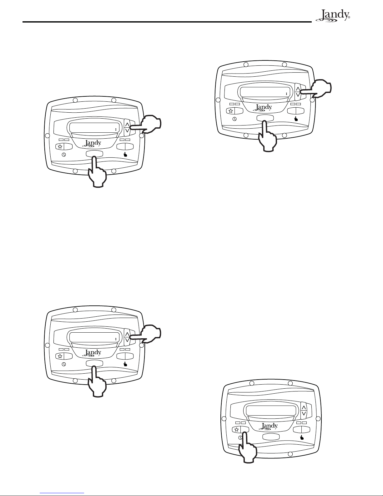
timer program. When the pump is activated via a remote
closure, the keypad is disabled and the message REMOTE
ENABLED appears on the display.
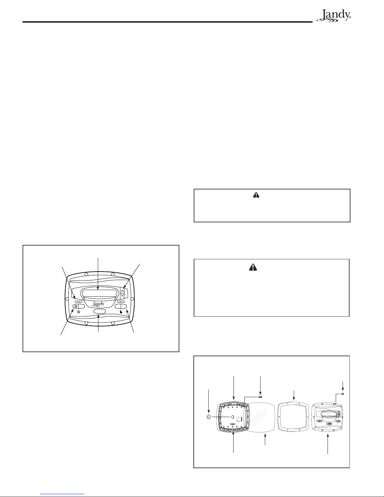
234
ePUMP
MENU
REMOTE ENABLED
10:00AM RPM:1200
The controller will remain in this state until the contact is
opened. When more than one (1) contact closure occurs, the
highest speed will take priority.
2.10 Remote Closure 4 Behavior
The behavior of speed "4" differs from manual operation
when operated via a remote contact closure. As during manual
operation, the turn-on time of remote closure 4 is immediate,
and occurs at the same time as contact closure (For example,
see Section 2.8). The turn-off time, however, is delayed by 30
minutes.
In other words, when remote closure 4 is de-activated, the
ePump™ will continue to run for 30 minutes, after which
time the controller will turn off the ePump™. The delay may
be manually interrupted by pressing any preset key.
2.10.1 Remote Closure 4 Application -
Booster Pump Support
The behavior of remote closure 4 may be used to allow an
external timeclock fitted with a 20-minute “fireman’s switch”
(e.g., Intermatic P/N 156T4042A) to properly control the
ePump™ in conjunction with a booster pump.
Connection for Booster Pump Support:
1. Turn off all switches and the main breaker that
supplies power to the ePump™.
WARNING
ELECTRICAL SHOCK HAZARD
Turn off all switches and the main breaker in the ePump™
electrical circuit before starting the procedure. Failure to
comply may cause a shock hazard resulting in severe
personal injury or death.
2. Install the normally-closed reman’s switch to the
timeclock assembly. (See timeclock manufacturer’s
instructions for details.)
3. Connect the main timeclock contacts to the booster
pump power input per the booster pump installation
manual.
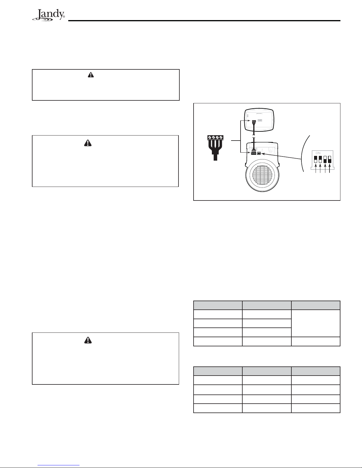
Figure 4. Connection to Remote Contacts
RS485
4321
RED
BLACK
YELLOW
GREEN
REMOTE CONTROL
54321
INPUT 2
INPUT 3
INPUT 4
COMMON
INPUT 1
J3
Remote Contact
Closure
input
common
2.8 Connection to Remote Contacts
The user interface allows speeds "" through "4" to operate
via remote contact closures (switch or relay). Speed "4"
operates differently than the other three. See Section 2.10,
Remote Closure 4 Behavior.
1. Turn off all switches and the main breaker that
supplies power to the ePump™.
WARNING
ELECTRICAL SHOCK HAZARD
Turn off all switches and the main breaker in the ePump™
electrical circuit before starting the procedure. Failure to
comply may cause a shock hazard resulting in severe
personal injury or death.
2. Connect one side of the remote contact closure to the
COMMON terminal on J3 REMOTE CONTROL
connector of the controller. See Figure 4.
3. Connect the other side of the remote contact closure
to INPUT 1, INPUT 2, INPUT 3, or INPUT 4
terminal on J3 REMOTE CONTROL connector of
the controller, depending on which speed is to be
controlled.
4. Turn on all switches and the main breaker feeding
power to the ePump™.
5. Verify the operation of the contact closures. If
the correct speed is activated when the closure is
activated, the ePump™ starts, and the message
REMOTE ENABLED appears on the controller
display.
NOTE When starting the pump via a remote closure, the
pump will first run at the priming speed for the
priming duration, as set by the installer.

Page 9
4. Connect one side of the reman’s switch to the
ePump™ Controller at J3 REMOTE CONTROL,
COMMON.
5. Connect the other side of the reman’s switch to the
ePump™ controller at J3 REMOTE CONTROL,
INPUT 4.
6. Set the timeclock to the desired on/off times.
7. Turn on all switches and the main breaker feeding
power to the ePump™.
8 If the installation is working properly, the reman’s
switch will open 20 minutes before the booster
pump shuts down, the ePump™ will continue to run
for 30 minutes, and the ePump™ Controller will
display PUMP WILL REMAIN ON FOR XX:XX,
where XX:XX is the time remaining until ePump™
shutdown.
Section 3. User Operation
3.1 OFF Mode
When the pump is off (not running), the controller displays
PRESS PRESET OR MENU/00:00 PUMP IS OFF,
where 00:00 is the time-of-day clock.
234
PRESS PRESET OR MENU
12:00AM PUMP IS OFF
ePUMP
MENU
3.2 RUN Mode
When the pump is running (not off), the controller displays
N:LABEL/00:00 RPM:XXXX, where n:label is the number
and label of the selected preset, 00:00 is the time-of-day
clock, and xxxx is the pump speed.
2:PRESET 2
10:00AM RPM: 1200
234
ePUMP
MENU
3.3 Manual Start and Stop
Up to eight (8) programmed speeds may be started from the
controller. Manual operation of speeds "eStar" through "4"
differs from manual operation of speeds "5" through "8".
NOTE When starting the pump, the pump will first run at the
priming speed for the priming duration, as set by the
installer.
3.3.1 Speeds eStar through 4
To start the pump manually running at speeds "eStar" through
"4", press button "" through "4" corresponding to the
desired speed. The associated LED will light red and the
controller enters the RUN mode.
234
ePUMP
MENU
2:PRESET 2
10:00AM RPM: 1200
To stop the pump, press the button again. The associated LED
will extinguish and the pump and controller will return to the
OFF mode.
3.3.2 Speeds 5 through 8
To start the pump manually at speeds "5" through "8",
press the MENU button. The controller displays SELECT
PRESET/N:LABEL, where n:label is the number and label
of the last selected preset "5" through "8".
Using the arrow keys, select the desired preset to activate,
and then press MENU to enter RUN mode, starting the pump
running at the selected speed.
234
SELECT PRESET
5:PRESET 5
ePUMP
MENU
To stop the pump, press MENU. To exit without starting the
pump, press any button "" through "4".
3.4 Pump Speed Setting
With the exception of preset "", the pump speed for each
preset may be adjusted while the pump is running in that
preset mode. Preset "" is reserved for the eStar function,
and its speed is set by the installer.

Page 10
To adjust the pump speed, the controller must be in the RUN
mode. While in RUN mode, the controller displays the pump
speed. Adjust the speed by pressing the up or down arrow
keys. The speed is saved by the controller and will remain
until changed again.
NOTE Pump speed is adjustable only within a certain range.
The minimum and maximum limits of the range are
set by the installer.
234
ePUMP
MENU
2:PRESET 2
10:00AM RPM: 1400
3.5 Timeclock Setup and Operation
The controller allows the user to create timed pump programs
on pump speeds (presets) "" and "2". The two timers
operate independently of each other, and may overlap in time
if desired.
3.5.1 Timeclock Setup
Start the desired speed, "" or "2". Press MENU. The
controller enters the Timeclock setup mode. Using the arrow
keys, select ON TIME and press MENU. Set the desired
pump turn-on time using the arrow keys and press MENU.
The time is stored. Select OFF TIME using the arrow keys
and press MENU. Set the desired pump turn-off time using
the arrow keys and press MENU. The time is stored.
234
ePUMP
MENU
2:PRESET 2 TIMECLOCK
ON TIME
Using the arrow keys, select TIMECLOCK. Select ENABLE
using the arrow keys. The program is now enabled to run.
Press the preset button ("" or "2") to return to the RUN
mode.
234
ePUMP
MENU
2:PRESET 2 TIMECLOCK
ENABLE
3.5.2 Timeclock Operation
When the pump is stopped, the associated green LED will
illuminate, indicating a timeclock program is enabled for that
speed.
If two (2) timed programs overlap, the program with the
faster speed will take priority and run to completion. If
the earlier-starting program is still active, it will resume
operation. The program off times never change, i.e., they are
not ‘pushed-out’ in time when programs overlap. Timeclock
programs may be prematurely stopped by stopping the pump
manually from the keypad. This override is active until the
program start time is reached again, at which time the timed
program will start the pump as programmed.
If the pump is started manually at a speed that has been
programmed with a timer, the pump will be stopped by the
timeclock at the programmed off time.
NOTE When starting the pump via a timed program, the
pump will first run at the priming speed for the
priming duration, as set by the installer. If a program
overlap occurs, the pump will immediately start at the
program speed without priming first.
3.5.3 Manually Overriding a Timer
Program
Timeclock programs may be prematurely stopped by pressing
the active preset key. This override is active until the program
start time is reached again, i.e., for 24 hours, at which time
the timed program will start the pump as programmed.
234
PRESS PRESET OR MENU
12:00AM PUMP IS OFF
ePUMP
MENU

Page 11
3.5.4 Timer Overriding a Manual On
If the pump is started manually at a speed that has been
programmed with a timer, the pump will be stopped by the
timeclock at the programmed off time. A clock icon appears
on the display when the timer has assumed control of the off
time.
Section 4. Service Setup Options
The service setup menu allows the installer to set various
operating parameters, view fault history, and restore factory
defaults.
Parameters that may be modified and set in the service setup
menu include:
Priming speed and duration.•
Minimum and maximum pump speeds.•
"• " eStar speed.
Pump Freeze Protect operation.•
4.1 Entering Service Setup
NOTE The ePumpTM user interface must be in the OFF
mode (all LED's lights must be off) before entering
the user setup mode. While in setup mode the user
interface will return back to the OFF mode after one
(1) minute since the last key press.
To enter the service setup menu, press and hold MENU, then
press and hold the "" and preset "4" keys. Hold all three
(3) keys down for five (5) seconds. To exit, press any preset
button.
234
ePUMP
MENU
PRESS PRESET OR MENU
12:00AM PUMP IS OFF
4.2 Minimum and Maximum Pump
Speeds
These speeds are considered global settings across the entire
controller, and create the range of allowable speed that may
be sent to the ePump™.
To set the minimum speed, from the service setup menu,
select SET MIN LIMIT using the arrow keys. Press MENU.
Using the arrow keys, set the minimum speed to the desired
value. Press MENU to accept and store.
234
SET MIN LIMIT
RPM: 600
ePUMP
MENU
To set the maximum speed, from the service setup menu,
select SET MAX LIMIT using the arrow keys. Press MENU.
Using the arrow keys, set the maximum speed to the desired
value. Press MENU to accept and store.
234
SET MAX LIMIT
RPM: 3450
ePUMP
MENU
4.3 Load Defaults
To restore factory default settings to the controller, from
the service setup menu, select LOAD DEFAULTS. Press
MENU. Using the arrow keys, select YES. Press MENU to
restore factory default settings.
234
LOAD DEFAULTS
YES
ePUMP
MENU

Page 12
4.4 Last Fault
This feature shows on the top display line, the most recent
unique fault message and on the bottom display line, the
second-to-last unique fault message. If there is no entry
for a fault, the display will show “*----------------*” on the
corresponding line. To select last fault, from the service setup
menu select LAST FAULT. Press MENU.
NOTE The fault messages are stored in non-volatile
memory, and remain even with no power. To clear the
fault history, press either arrow key.
234
SELECT SERVICE SETUP
LAST FAULT
ePUMP
MENU
4.5 Priming Speed and Duration
The ePump™ controller will command the ePump™ to
operate at the priming speed for the priming duration
specified (except during timer program overlaps or follow-on
commands where the pump is not stopped before changing
speeds). From the service setup menu, select PRIMING using
the arrow keys. Press MENU.
234
PRIMING DURATION
MIN: 3
ePUMP
MENU
To set priming speed, select PRIMING SPEED using the
arrow keys. Press MENU. Using the arrow keys, set the
priming speed to the desired value. Press MENU to accept
and store.
234
PRIMING SPEED
RPM: 3450
ePUMP
MENU
To set priming duration, select PRIMING DURATION using
the arrow keys. Press MENU. Using the arrow keys, set the
priming speed to the desired value in minutes from 1 to 5
minutes. Press MENU to accept and store.
234
PRIMING DURATION
MIN: 3
ePUMP
MENU
4.6 eStar Speed
The "" speed is intended to be used as an energy-efficient
setting that can be easily called-up by activating the eStar
preset speed from the keypad or remote closure. After this
speed has been determined by the installer, the eStar preset
may be set as follows: From the service setup menu, select
SET ESTAR SPEED. Press MENU. Using the arrow keys,
set the speed to the desired value. Press MENU to accept and
store.
234
1:eSTAR
RPM:1250
ePUMP
MENU
4.7 Pump Freeze Protect Operation
When enabled to do so, the ePump™ controller monitors the
temperature inside the pump and will activate the ePump™
at the eStar speed when the temperature approaches freezing.
The run duration of the pump freeze protect operation is
adjustable from 30 minutes to 8 hours, or may be disabled
completely.

Page 13
To set the pump freeze protect operation, from the service
setup menu select PUMP FREEZE PROTECT. Press
MENU. Using the arrow keys, set the duration to the desired
value. To disable pump freeze protect, set the duration to
0:00. Press MENU to accept and store.
234
PUMP FREEZE PROTECT
1:05
ePUMP
MENU
Important Information on Freeze Protection
Freeze protection is intended to protect equipment and
plumbing for short periods of freezing only. It does this
by activating the filtration pump and circulating the water
to prevent freeze inside equipment or plumbing. Freeze
protection does not guarantee that equipment will not be
damaged by extended periods of freezing temperatures
or power outages. In these conditions, the pool and spa
should be shut down completely (e.g. drained of water and
closed for the winter) until warmer weather exists.
The pump freeze protect run time may be interrupted by
pressing a preset key, as follows:
Pressing the key "" once overrides the pump freeze protect
run time, pressing it twice turns off the pump. Pressing other
preset keys will override the pump freeze protect run time and
activate the selected preset speed.
234
ePUMP
MENU
PUMP FREEZE PROTECT
1: FILTRATION
4.8 Selecting Pump Type
This feature is preset by factory default. At this time, the
ePump™ controller does not support other types of pumps.
Section 5. User Set Up Options
NOTE The ePumpTM user interface must be in the OFF
mode before entering the user setup mode. While in
setup mode the user interface will return back to the
OFF mode after one (1) minute since the last key
press.
When in setup mode, preset keys "" through "4" are used
as ‘escape’ or exit keys while navigating the setup menu.
To enter the setup mode, press and hold the MENU button
for five (5) seconds. The controller displays SELECT USER
SETUP. Using the arrow keys, select the desired setup item
to change.
5.1 Setting Time-of-Day
From the Setup menu, select SET TIME. Press the MENU
button to display the currently-set time. Using the arrow keys,
adjust to the desired time. Press MENU to save your setting.
234
ePUMP
MENU
SELECT USER SETUP
SET TIME
5.2 Labeling Presets
The ePump™ controller comes from the factory with pre-
programmed labels or names for the preset speeds. The labels
may be changed as desired to suit your particular installation.
Two types of labels are provided by the controller:
General Labels - selected from a list•
Custom Labels - created by the user•
From the setup menu, select LABEL PRESET. Press the
MENU button to display the currently selected Preset. Using
the arrow keys, choose the preset to be changed. Press MENU
to select. The controller displays SELECT LABEL TYPE.
Select GENERAL or CUSTOM as desired using the arrow
keys.
234
ePUMP
MENU
SELECT USER SETUP
LABEL PRESET

Page 14
5.3 General Labels
Using the arrow keys, select a general label from the list to
assign to the Preset. Press MENU to assign the label to the
Preset.
234
ePUMP
MENU
LABEL PRESET
FILTRATION
5.4 Custom Labels
In the custom label mode, the controller displays a flashing
cursor at the character position to be changed. Using the
arrow keys, change the character as desired. Press MENU to
accept the change and advance to the next character position.
Press any preset key "" through "4" to return to the
previous cursor position.
234
ePUMP
MENU
LABEL PRESET
1:PRESET 1
Continue this procedure until the end of the label is reached.
The new label is saved when MENU is pressed at the last
character position.
5.5 Display Light Control
The controller’s display is equipped with a backlight to aid
viewing in low light conditions.
From the setup menu, select DISPLAY LIGHT. Press
MENU. Using the arrow keys, select the desired operating
mode for the display backlight:
LIGHT OFF: Turn off display backlight.
LIGHT ON: Turn on display backlight.
2 MIN TIMEOUT: Turn on display backlight, with automatic
turn-off after two (2) minutes since the last key press.
234
ePUMP
MENU
SELECT USER SETUP
DISPLAY LIGHT
5.6 Language Selection
From the setup menu, select LANGUAGE using the arrow
keys. Press MENU. Using the arrow keys, select the desired
language. Press MENU to save the selection.
234
ePUMP
MENU
SELECT USER SETUP
LANGUAGE
5.7 Run Duration (Presets 3 and 4 Only)
Presets "3" and "4" may be programmed to run for a specified
duration after being manually started. This run duration
is programmable from 30 minutes to eight (8) hours, in
increments of 30 minutes. A setting of 0:00 disables the run
duration feature, allowing the preset to run indefinitely.
From the setup menu, select RUN DURATION. Press
MENU. Using the arrow keys, select the preset to be
programmed. Press MENU. Set the desired run duration for
the preset using the arrow keys. Press MENU to accept.
234
ePUMP
MENU
SELECT USER SETUP
RUN DURATION

Page 15
Section 6. Menu Flow Chart
[OFF]
USER SETUP
(Note 6)
ON TIME
SET TO [10:00AM]
DISPLAY LIGHT
[ 2 MIN TIME OUT ]
(Note 8)
LIGHT OFF
LIGHT ON
PRESET X
(Note 5)
SET TO [2750] RPM
R: MIN TO MAX
I: 10RPM
(Note 2)
SET TIME
TIMECLOCK
[DISABLE]
ENABLE
SET TO [12:00AM]
R: 12:00AM TO
11:59PM
I: 1 MIN
LANGUAGE
SELECTION
(Note 7)
[ENGLISH]
SPANISH
FRENCH
LABEL
PRESET
SELECT
PRESET
SET TO [5]
R: 5 TO 8
I: 1
PRESET 3 OR 4
(Note 1,4)
SET TO [2750] RPM
R: MIN TO MAX
I: 10RPM
(Note 2)
SET TO [12:00AM]
R: 12:00AM TO
11:59PM
SET TO [12:00AM]
R: 12:00AM TO
11:59PM
NOTES
Default parameters are shown in [ ].
“R” stands for Range.
“I” stands for Increment.
1. Accessed directly by front panel button.
2. Occurs at Run Screen.
3. Timeclock features accessed via MENU button while
Preset is running.
4. MENU button has no effect when running.
5. Accessed via MENU button when pump is stopped.
6. Press and hold MENU button for 5 seconds to enter.
7. Is not affected when “LOAD DEFAULTS” is executed.
8. Key
that is pressed to wake up display is also acted upon.
9. Press and hold MENU, eStar, and 4 simultaneously
for 5 seconds to enter.
10. Setting not saved in non-volatile memory; reset to “NO”
after execution.
USE
USER
SETUP
SET TO [“PRESET n”]
R: ALL CHARS
SELECT
LABEL TYPE
GENERAL
CUSTOM
LABEL LIST
PRESET 2
(Note 1,3)
SET TO [2750]RPM
R: MIN TO MAX
I: 10RPM
(Note 2,3)
RUN
DURATION
SELECT
PRESET
SET TO [0:00]
R: 30 MIN TO 8 HRS
I: 30 MIN
eSTAR
(Note 1,3)
OFF TIME
SET TO [4:00PM]
SERVICE SETUP
(Note 9)
LOAD DEFAULTS
(Note 10)
[NO]
YES
LAST FAULT
[LAST FAULT]
[2ND TO LAST]
SET MIN LIMIT
SET TO [600]
R: 600 TO MAX LIM
I: 10
SET MAX LIMIT
SET TO [3450]
R: MIN LIM TO 3450
I: 10 SET ESTAR
SPEED
SET TO [1750]RPM
R: MIN TO MAX
I: 10RPM
SET TO [0:30]
R: 0 MIN TO 8 HRS
I: 30 MIN
PUMP
TYPE
[ePUMP]
VSP AC
PRIMING
[SPEED]
DURATION
SET TO [2750]
R: MIN LIM TO
SET TO [1]
R: 1 TO 5 MIN
DISPLAY POWER
USAGE
[NO]
YES
TIMECLOCK
[DISABLE]
ENABLE
SET TO [12:00AM]
R: 12:00AM TO
11:59PM
SET TO [12:00AM]
R: 12:00AM TO
11:59PM
OFF TIME
SET TO [4:00PM]
ON TIME
SET TO [10:00AM]
FREEZE
PROTECT
SERVICE
SETUP

H0311300A
6000 Condor Drive • Moorpark, CA USA 93021 • 800.822.7933 • Fax 877.327.1403
Zodiac Pool Systems, Inc.
This warranty is limited to the first retail purchaser, is not transferable, and does not apply to products that
have been moved from their original installation sites. The liability of Zodiac Pool Systems, Inc. shall not
exceed the repair or replacement of defective parts and does not include any costs for labor to remove
and reinstall the defective part, transportation to or from the factory, or any other materials required to make
the repair. Refrigerant or other expendables are not covered by the warranty. This warranty does not cover
failures or malfunctions resulting from the following:
LIMITED WARRANTY
• AquaLink® RS units installed with Jandy
®
Surge Protection Kits will be covered for two (2) years.
• Never Lube® valves are warranted for the life of the pool and/or spa on which they were originally installed.
• AquaPure® Electronic Chlorine Generator Electrolytic Cells carry a five (5) year limited warranty on a prorated basis.
• Heat pumps are covered for two (2) years. There is a lifetime warranty on titanium tubing.
• The heat pump compressor is covered for five (5) years.
1. Failure to properly install, operate, or maintain the product(s) in accordance with our pubished Installation,
Operation and Maintenance Manuals, which are provided with the product(s).
2. The workmanship of any installer of the product(s).
3. Not maintaining a proper chemical balance in your pool and/or spa [pH levels between 7.2 and 7.8, with
ideal ranges being between 7.4 and 7.6, Total Alkalinity (TA) between 80 to 120 ppm,
Total Dissolved Solids (TDS) less than 2000, not including salt ppm].
4. Abuse, alteration, accident, fire, flood, lightning, rodents, insects, negligence, or acts of God.
5. Scaling, freezing, or other conditions causing inadequate water circulation.
6. Operating the product(s) at water flow rates outside the published minimum and maximum specifications.
7. Use of non-factory authorized parts or accessories in conjunction with the product(s).
8. Chemical contamination of combustion air or improper use of sanitizing chemicals, such as introducing
sanitizing chemicals upstream of the heater and cleaner hose or through the skimmer.
9. Overheating; incorrect wire runs; improper electrical supply; collateral damage caused by failure of O-rings,
DE grids, or cartridge elements; or damage caused by running the pump with insufficient quantities of water.
LIMITATION OF LIABILITY:
This is the only warranty given by Zodiac Pool Systems, Inc. No one is authorized to make any other warranties
on behalf of Zodiac Pool Systems, Inc. THIS WARRANTY IS IN LIEU OF ALL OTHER WARRANTIES,
EXPRESSED OR IMPLIED, INCLUDING, BUT NOT LIMITED TO, ANY IMPLIED WARRANTIES OF FITNESS
FOR A PARTICULAR PURPOSE AND MERCHANTABILITY. ZODIAC POOL SYSTEMS, INC. EXPRESSLY
DISCLAIMS AND EXCLUDES ANY LIABILITY FOR CONSEQUENTIAL, INCIDENTAL, INDIRECT, OR
PUNITIVE DAMAGES FOR BREACH OF ANY EXPRESSED OR IMPLIED WARRANTY. This warranty
gives you specific legal rights. You may also have other rights that vary by state or province.
WARRANTY CLAIMS:
For prompt warranty consideration, contact your dealer and provide the following information: proof of purchase,
model number, serial number, and date of installation. The installer will contact the factory to obtain instructions
regarding the claim and to determine the location of the nearest designated service center. If the dealer is not
available, you can locate a service center in your area by visiting www.jandy.com or by calling our technical
support department at 1.800.822.7933. All returned parts must have a Returned Material Authorization number
to be evaluated under the terms of this warranty.
Thank you for purchasing Jandy®pool and spa products. Zodiac Pool Systems, Inc. warrants all parts to be
free from manufacturing defects in materials and workmanship for a period of one (1) year from the date of
retail purchase, with the following exceptions:
Litho in U.S.A. © Zodiac Pool Systems, Inc. 0810
Table of contents
Other Jandy Water Pump manuals

Jandy
Jandy SHPF User manual

Jandy
Jandy JCP Series User manual

Jandy
Jandy FHPM10 User manual

Jandy
Jandy VS PLUSHP 2.7 HP User manual

Jandy
Jandy VSFHP185DV2A User manual

Jandy
Jandy WFTR User manual

Jandy
Jandy FHP Series User manual

Jandy
Jandy HHPlus Series User manual

Jandy
Jandy Stealth SHPM User manual

Jandy
Jandy FHPM User manual
Popular Water Pump manuals by other brands

GORMAN-RUPP
GORMAN-RUPP 03H3-GR Installation, operation and maintenance manual

Hilti
Hilti DWP 10 operating instructions

Seko
Seko PoolMatch pH instruction manual

Grundfos
Grundfos ALPHA1 L Series Installation and operating instructions

ABNOX
ABNOX AXFP2-Light Series operating manual

Makita
Makita EW100R instruction manual