Jandy Pro VSPHP270JEP Owner's manual

H0490000_REVE
WARNING
FOR YOUR SAFETY - This product must be installed and serviced by a contractor who is licensed and
qualified in pool equipment by the jurisdiction in which the product will be installed where such state
or local requirements exist. The maintainer must be a professional with sufficient experience in pool
equipment installation and maintenance so that all of the instructions in this manual can be followed
exactly. Before installing this product, read and follow all warning notices and instructions that accompany
this product. Failure to follow warning notices and instructions may result in property damage, personal
injury, or death. Improper installation and/or operation will void the warranty.
Improper installation and/or operation can create unwanted electrical hazard which can cause serious
injury, property damage, or death.
ATTENTION INSTALLER - This manual contains important information about the
installation, operation and safe use of this product. This information should be given to
the owner/operator of this equipment.
ENGLISH |FRANÇAIS | ESPAÑOL
Jandy Pro Series
VS PlusHP Pumps
Models VSPHP270JEP
& VSPHP270AUT
INSTALLATION AND
OPERATION MANUAL

Page 2 ENGLISH Jandy®Pro Series VS PlusHP Pumps |Installation & Operation Manual
EQUIPMENT INFORMATION RECORD
DATE OF INSTALLATION
INSTALLER INFORMATION
INITIAL PRESSURE GAUGE READING (WITH CLEAR FILTER)
PUMP MODEL HORSEPOWER
NOTES:
Section 1. Important Safety Instructions ........... 3
1.1 Safety Instructions .............................................3
1.2 Pool Pump Suction Entrapment Prevention
Guidelines..........................................................5
Section 2. General Description ........................... 6
2.1 Introduction ........................................................6
2.2 Description.........................................................6
2.3 Preparation ........................................................6
Section 3. Installation........................................... 6
3.1 Plumbing............................................................6
3.2 Electrical Installation ..........................................8
Section 4. Operation............................................. 12
4.1 Remove Pump Lid ............................................12
4.2 Conduct Pressure Test ......................................13
4.3 Start-up ..............................................................13
TABLE OF CONTENTS
Section 5. Maintenance........................................ 14
5.1 Routine Maintenance.........................................14
5.2 Winterizing the Pump.........................................14
Section 6. Troubleshooting and Repair.............. 15
Section 7. Product Specications and Technical
Data...................................................... 17
7.1 Replacement Parts List......................................17
7.2 Exploded View ...................................................17
7.3 Performance Curves..........................................18
7.4 PhysicalandOperationalSpecications............18

Page 3
ENGLISH
Jandy®Pro Series VS PlusHP Pumps |Installation & Operation Manual
Section 1. Important Safety Instructions
READ AND FOLLOW ALL INSTRUCTIONS
1.1 Safety Instructions
All electrical work must be performed by a licensed electrician and conform to all national, state, and local codes.
When installing and using this electrical equipment, basic safety precautions should always be followed, including the
following:
WARNING
To reduce the risk of injury, do not permit children to use this product.
WARNING
To reduce the risk of property damage or injury, do not attempt to change the backwash (multiport, slide, or full
ow)valvepositionwiththepumprunning.
WARNING
Jandy Pro Series pumps are powered by a high voltage electric motor and must be installed by a licensed or
certiedelectricianoraqualiedswimmingpoolservicetechnician.
WARNING
RISK OF ELECTRIC SHOCK, FIRE, PERSONAL INJURY, OR DEATH. Connect only to a branch circuit that is
protectedbyaground-faultcircuit-interrupter(GFCI).Contactaqualiedelectricianifyoucannotverifythatthe
circuit is protected by a GFCI. A GFCI should be provided by the installer and should be tested on a routine basis.
To test the GFCI, push the test button. The GFCI should interrupt power. Push the reset button. Power should
be restored. If the GFCI fails to operate in this manner, the GFCI is defective. If the GFCI interrupts power to
thepumpwithoutthetestbuttonbeingpushed,agroundcurrentisowing,indicatingthepossibilityofelectrical
shock.Donotusethepump.Disconnectthepumpandhavetheproblemcorrectedbyaqualiedservice
representative before using.
Duetothepotentialriskofre,electricshock,orinjuriestopersons,ZodiacPumpsmustbeinstalled
in accordance with the National Electrical Code®(NEC®),alllocalelectricalandsafetycodes,andthe
Occupational Safety and Health Act (OSHA®).CopiesoftheNECmaybeorderedfromtheNational
Fire Protection Association (NFPA®)onlineatwww.nfpa.orgorcall617-770-3000,orcontactyourlocal
government inspection agency.
InCanada,ZodiacPumpsmustbeinstalledinaccordancewiththeCanadianElectricalCode(CEC).
WARNING
Incorrectlyinstalledequipmentmayfail,causingsevereinjuryorpropertydamage.
WARNING
• Do not connect the system to an unregulated city water system or other external source of pressurized water
producing pressures greater than 35 PSI.
• Trappedairinsystemcancausethelterlidtobeblownoff,whichcanresultindeath,seriouspersonalinjury,
or property damage. Be sure all air is out of the system before operating.
WARNING
RISK OF SUCTION ENTRAPMENT HAZARD, WHICH, IF NOT AVOIDED, CAN RESULT IN SERIOUS INJURY
OR DEATH. Do not block pump suction as this can cause severe injury or death. Do not use this pump for wading
pools, shallow pools or spas containing bottom drains, unless the pump is connected to at least two functioning
suctionoutlets.Suctionoutlet(drain)assemblies and covers must be certified to the latest published version of
ANSI®/ASME®A112.19.8, or its successor standard, ANSI/APSP-16.

Page 4 ENGLISH Jandy®Pro Series VS PlusHP Pumps |Installation & Operation Manual
SAVE THESE INSTRUCTIONS
WARNING
Chemicalspillsandfumescanweakenpool/spaequipment.Corrosioncancauseltersandotherequipmentto
fail,resultinginsevereinjuryorpropertydamage.Donotstorepoolchemicalsnearyourequipment.
CAUTION
Do not start pump dry! Running the pump dry for any length of time will cause severe damage and will void the
warranty.
WARNING
Tominimizetheriskofsevereinjuryordeaththelterand/orpumpshouldnotbesubjectedtothepipingsystem
pressurization test.
Localcodesmayrequirethepoolpipingsystemtobesubjectedtoapressuretest.Theserequirementsare
generallynotintendedtoapplytothepoolequipmentsuchasltersorpumps.
Zodiac®poolequipmentispressuretestedatthefactory.
However,iftheWARNINGcannotbefollowedandpressuretestingofthepipingsystemmustincludethelter
and/or pump, BE SURE TO COMPLY WITH THE FOLLOWING SAFETY INSTRUCTIONS:
• Check all clamps, bolts, lids, lock rings and system accessories to ensure they are properly installed and
secured before testing.
• RELEASE ALL AIR in the system before testing.
• Water pressure for test must NOT EXCEED 35 PSI.
• WatertemperaturefortestmustNOTEXCEED100°F(38°C).
• Limit test to 24 hours. After test, visually check system to be sure it is ready for operation.
NOTICE:TheseparametersapplytoZodiacequipmentonly.Fornon-Zodiacequipment,consultequipment
manufacturer.
CAUTION
This pump is for use with permanently installed pools and may also be used with hot tubs and spas if so marked.
Do not use with storable pools. A permanently installed pool is constructed in or on the ground or in a building
such that it cannot be readily disassembled for storage. A storable pool is constructed so that it may be readily
disassembled for storage and reassembled to its original integrity.
CAUTION
Donotinstallwithinanoutdoorenclosureorbeneaththeskirtofahottuborportablespa.Thepumprequires
adequateventilationtomaintainairtemperatureatlessthanthemaximumambienttemperatureratinglistedon
the motor rating plate.

Page 5
ENGLISH
Jandy®Pro Series VS PlusHP Pumps |Installation & Operation Manual
1.2 Pool Pump Suction Entrapment Prevention Guidelines
WARNING
Pump suction is hazardous and can trap and drown or disembowel bathers. Do not use or operate
swimming pools, spa, or hot tubs if a suction outlet cover is missing, broken, or loose. The following
guidelines provide information for pump installation that minimizes the risk of injury to users of pools, spas, and
hot tubs:
Entrapment Protection - The pump suction system must provide protection against the hazards of suction
entrapment.
Suction Outlet Covers - All suction outlets must have correctly installed, screw-fastened covers in place. All
suctionoutlet(drain)assembliesandtheircoversmustbeproperlymaintained.Suctionoutlets(drain)assemblies
andtheircoversmustbelisted/certiedtothelatestversionofANSI®/ASME®A112.19.8 or its successor standard,
ANSI/APSP-16. They must be replaced if cracked, broken, or missing.
Number of Suction Outlets Per Pump-Provideatleasttwo(2)hydraulically-balancedmaindrains,withcovers,
assuctionoutletsforeachcirculatingpumpsuctionline.Thecentersofthemaindrains(suctionoutlets)onany
one(1)suctionlinemustbeatleastthree(3)feetapart,centertocenter.SeeFigure1.
The system mustbebuilttoincludeatleasttwo(2)suctionoutlets(drains)connectedtothepumpwhenever
thepumpisrunning.However,iftwo(2)maindrainsrunintoasinglesuctionline,thesinglesuctionlinemaybe
equippedwithavalvethatwillshutoffbothmaindrainsfromthepump.Thesystemshallbeconstructedsuchthat
it shall not allow for separate or independent shutoff or isolation of each drain. See Figure 1.
Morethanone(1)pumpcanbeconnectedtoasinglesuctionlineaslongastherequirementsabovearemet.
Water Velocity - The maximum water velocity through the suction outlet assembly and its cover for any suction
outletmustnotexceedthesuctionttingassemblyandit’scover’smaximumdesignowrate.Thesuctionoutlet
(drain)assemblyanditscovermustcomplywiththelatestversionofANSI/ASMEA112.19.8,thestandardfor
Suction Fittings For Use in Swimming Pools, Wading Pools, Spas, and Hot Tubs, or its successor standard, ANSI/
APSP-16.
If100%ofthepump’sowcomesfromthemaindrainsystem,themaximumwatervelocityinthepumpsuction
hydraulicsystemmustbesix(6)feetpersecondorless,evenifone(1)maindrain(suctionoutlet)iscompletely
blocked.Theowthroughtheremainingmaindrain(s)mustcomplywiththelatestversionofANSI/ASME
A112.19.8 or its successor standard, ANSI/APSP-16, the standard for Suction Fittings For Use in Swimming
Pools, Wading Pools, Spas, and Hot Tubs.
Testing and Certication - Suction outlet assemblies and their covers must have been tested by a nationally
recognized testing laboratory and found to comply with the latest version of ANSI/ASME A112.19.8 or its
successor standard, ANSI/APSP-16, the standard for Suction Fittings For Use in Swimming Pools, Wading Pools,
Spas, and Hot Tubs.
Fittings-Fittingsrestrictow;forbestefciencyusefewestpossiblettings(butatleasttwo(2)suctionoutlets).
Avoidttingswhichcouldcauseanairtrap.
PoolcleanersuctionttingsmustconformtoapplicableInternationalAssociationofPlumbingandMechanical
Ofcials(IAPMO)standards.
SUCTION HAZARD. Can cause serious injury or death. Do not use this pump for
wading pools, shallow pools or spas containing bottom drains, unless the pump is
connected to at least two (2) functioning suction outlets.
WARNING

Page 6 ENGLISH Jandy®Pro Series VS PlusHP Pumps |Installation & Operation Manual
Section 2. General Description
2.1 Introduction
This manual contains information for the proper
installation, operation, and maintenance of Jandy Pro
Series VS Plus HP pumps. Procedures in this manual
must be followed exactly. To obtain additional copies
of this manual, contact Zodiac Pool Systems LLC at
1.800.822.7933 or visit www.zodiacpoolsystems.com.
2.2 Description
The VS Plus HP is a variable-speed pump that can
run from 600-3450 RPM. When connected to the
JEP-R controller, up to eight (8) speed settings may
be programmed and recalled. This allows you to select
the most appropriate speed for your application. Even
more versatile programming is possible when you use
an AquaLink® RS, AquaLink PDA, or AquaLink Z4
controller.
The pump is driven by a variable speed ECM
(Electronically Commutated Motor) directly attached
to the pump impeller which forces water ow. The rate
variability allows for optimal ow during various pump
cycles. As a result, the energy efciency of the pump is
maximized which means cost savings to the pool owner
while also helping to save the environment.
2.3 Preparation
1. Check the carton for damage. Open the carton
and check for concealed damage, such as cracks,
dents, or a bent base. If you nd damage, contact
the shipper or the distributor where the pump was
purchased.
2. Inspect the contents of the carton and verify that
all parts are included. See “Figure 1. Carton
Contents”.
Figure 1. Carton Contents
02
01
03
04 05
06
07
09
08
15
10
11
12
13
14
01
02
03
04
05
06
07
08
09
10
11
12
13
14
15
VSPHP27 Pump
Installation and Operation Manual
Large Drawstring Bag
Universal Union Nut
Tailpiece
O-Ring
Small Drawstring Bag
User Interface Universal Control
Backplate Universal Control
DIP Switch Label
Cable Label
4 Conductor Cable
Terminal Bar 4 Pin
Manilla Envelope
Mounting Screw
1
1
1
2
2
2
1
1
1
1
1
1
1
1
6
ITEM DESCRIPTION QTY
For VSPHP27JEP Models only
- For a complete list of replacement parts
please see section 7.1
Section 3. Installation
3.1 Plumbing
3.1.1 Pump Location
WARNING
ToReducetheRiskofFire,installpoolequipmentin
an area where leaves or other debris will not collect on
oraroundtheequipment.Keepsurroundingareaclear
of all debris such as paper, leaves, pine-needles and
other combustible materials.
1. Zodiac Pool Systems LLC recommends installing
the pump no more than one (1) foot (30 cm) above
water level. The pump should not be installed
more than ve (5) feet above the water level of
the pool. It is recommended that a check valve be
installed when pump is installed more than 3 feet
above water level.
NOTE ThepumpisNSF-certiedforprimingatheights
upto10ft.abovethewaterlevel.However,to
achieve better self-priming, install the pump as
close as possible to the water level of the pool.
2. If the pump is located below water level, isolation
valves must be installed on both the suction
and return lines to prevent pool water back ow
during routine or required servicing.
WARNING
A check valve can interfere with the proper operation
ofcertainSuctionVacuumReleaseSystem(SVRS)
products. To avoid possible entrapment hazard, seri-
ous injury, or death, make sure to review the opera-
tion/owners manual of your particular SVRS product
before installing the check valve.

Page 7
ENGLISH
Jandy®Pro Series VS PlusHP Pumps |Installation & Operation Manual
NOTE Whenthepoolequipmentislocatedbelowthe
pool surface a leak can result in large scale
waterlossorooding.ZodiacPoolSystems
LLC cannot be responsible for such water
loss,oodingordamagecausedbyeither
occurrence.
3. Install the pump such that any disconnecting means
and/or junction boxes for power connection are
within sight of the pump and at least ve (5) feet
horizontally from the edge of the pool and/or spa.
4. Choose a location that will minimize turns in the
piping.
NOTE In Canada, the minimum distance maintained
from the edge of the pool and/or spa as noted
abovemustbe3meters(10feet),asrequired
by the Canadian Electrical Code (CEC, CSA
C22.1).
5. The pump must be placed on a solid foundation
that will not vibrate.
NOTE: To further reduce the possibility of vibration
noise, bolt the pump to the foundation, or place
it on a rubber mat.
6. The pump foundation must have adequate
drainage to prevent the motor from getting wet.
7. Protect the pump from the rain and sun.
Figure 2. Typical Piping Installation
MAIN DRAINS
(Suction Outlet)
Optional
Cleaner Suction Port
MANUAL BYPASS VALVE
HEATER
FILTER
CHECK VALVE
(Check Valve recommended
for systems installed with Erosion Feeders
or Aquapure salt chlorination systems)
PUMP
POOL/SPA
3 WAY VALVE
SPA DRAIN
(Suction Outlet)
SKIMMER
SPA RETURN
POOL
RETURN
a.
a.
MANUAL BY-PASS DETAIL:
USE WHEN FILTRATION RATE
EXCEEDS 125 GPM FOR ZODIAC
HEATERS. REFER TO THE MANUFAC-
TURER’S RECOMMENDATIONS IF
USING A DIFFERENT BRAND HEATER.
8. Proper ventilation is required for the pump to
operate normally. Motor generated heat must be
removed by adequate air ow.
9. Provide access for future service by leaving a
clear area around the pump. Allow plenty of space
above the pump to remove the lid and basket.
10. If the equipment is under cover, provide adequate
lighting.
3.1.2 Pipe Sizing
If pump is located within 50 feet (15 m) of the pool,
the recommended minimum pipe size for suction and
discharge is 2.5 inches (64 mm). For lengths greater
than 50 feet increase the pipe size according to “Table 1.
Pipe Sizing for Schedule 40 PVC”.
3.1.3 Installation Recommendations
1. To help prevent dif culty in priming, install the
suction pipe without high points (above inlet of
pump, or inverted “U”s, commonly referred to in
plumbing as “airlocks”) that can trap air.
2. For installations of equipment up to 100 feet
(30 m) from the water, refer to “Table 1. Pipe
Sizing for Schedule 40 PVC”, For installations
of equipment more than 100 feet (30 m) from
the water, the recommended pipe size must be
increased to the next size.

Page 8 ENGLISH Jandy®Pro Series VS PlusHP Pumps |Installation & Operation Manual
Table 1. Pipe Sizing for Schedule 40 PVC
Pipe Size
Maximum Flow
Suction
(6 feet per second)
Maximum Flow
Discharge
(8 feet per second)
1½"(38mm) 37GPM(140LPM) 50GPM(189LPM)
2"(51mm) 62GPM(235LPM) 85GPM(322LPM)
2½"(64mm) 88GPM(333LPM) 120GPM(454LPM)
3"(76mm) 136GPM(515LPM) 184GPM(697LPM)
4"(102mm) 234GPM(886LPM) 313GPM(1185LPM)
3. The pump comes equipped with unions on both
the suction and discharge ports. This feature
simplies installation and service and eliminates
the possibility of leaks at threaded adapters.
4. The pump must be connected to at least two (2)
hydraulically-balanced main drains for each pool
pump suction line. Each drain (suction outlet)
assembly must be equipped with covers and must
be listed or certied to the latest published edition
of ANSI®/ASME®A112.19.8, or its successor
standard, ANSI/APSP-16. The suction ttings of
the main drains must be at least three (3) feet (1
m) apart or at different planes. The suction ttings
can be a drain and skimmer, two (2) drains, two
(2) skimmers, or a skimmer with an equalizer
line installed. Check the local codes for proper
installation.
NOTE To prevent entrapment, the system must be
built so it cannot operate with the pump drawing
waterfromonlyone(1)maindrain.Atleasttwo
(2)maindrainsmustbeconnectedtothepump
whenitisinoperation.Iftwo(2)maindrainsrun
into a single suction line, the single suction line
maybeequippedwithavalvethatwillshutoff
both main drains from the pump.
Figure 3. Number of Suction Outlets Per Pump
Listed/certified to the latest
published version of
ANSI/ASME A112.19.8 or
its successor standard,
ANSI/APSP-16.
Anti-entrapment
Cover/Grate or Suction
Fitting, securely-fastened
to Main Drain Sump
Listed/certified to the latest
published version of
ANSI®/ASME®A112.19.8 or
its successor standard,
ANSI/APSP-16.
Anti-entrapment
Cover/Grate or Suction
Fitting, securely fastened to
Main Drain Sump
At Least
3 Feet
Suction Outlet
(Main Drain)
Suction Outlet
(Main Drain)
Valves permitted only after tee Pump
No valves between
Tee and Main Drains
Skimmer
5. The piping must be well supported and not forced
together where it will experience constant stress.
6. Always use properly sized valves. Jandy Pro
Series Diverter Valves and Ball Valves typically
have the best ow capabilities.
7. Use the fewest ttings possible.
NOTE Ifmorethanten(10)suctionttingsareneeded,
the pipe size must be increased.
8. Every new installation must be pressure tested
according to local codes.
3.2 Electrical Installation
3.2.1 Voltage Checks
The correct voltage, as specied on the pump data plate,
is necessary for proper performance and long motor life.
Incorrect voltage will decrease the pump’s ability to
perform and can cause overheating, reduce motor life,
and result in higher electric utility cost.
It is the responsibility of the electrical installer to
provide the correct operating voltage to the pump by
ensuring proper circuit sizes and wire sizes for the
specic application.
The National Electrical Code®(NEC®, NFPA-70)
requires all pool pump circuits be protected with a
Ground Fault Interrupter (GFCI). Therefore, it is also
the responsibility of the electrical installer to ensure that
the pump circuit is in compliance with this and all other
applicable requirements of the National Electrical Code
(NEC) and any other applicable installation codes.

Page 9
ENGLISH
Jandy®Pro Series VS PlusHP Pumps |Installation & Operation Manual
CAUTION
Failuretoprovidedataplatevoltage(within10%)during
operation will cause the motor to overheat and void
the warranty.
3.2.2 Bonding and Grounding
1. In addition to being properly grounded and in
accordance with the requirements of the National
Electrical Code (NEC), or in Canada the Canadian
Electrical Code (CEC), the pump motor must
be bonded to all metal parts of the swimming
pool, spa or hot tub structure and to all electrical
components and equipment associated with the
pool/spa water circulation system.
2. The bonding must be accomplished by using a
solid copper conductor, No. 8 AWG or larger. In
Canada No. 6 AWG or larger must be used. Bond
the motor using the external bonding lug provided
on the motor frame.
WARNING
Always disconnect the power source before working
on a motor or its connected load.
WARNING
Make sure that the control switch, time clock, or control
system is installed in an accessible location, so that in
theeventofanequipmentfailureoralooseplumbing
fitting,theequipmentcanbeturnedoff.Thislocation
must not be in the same area as the pool pump, filter,
andotherequipment.
CAUTION
The pump must be permanently connected to a
dedicatedelectricalcircuit.Nootherequipment,
lights, appliances, or outlets may be connected to the
pump circuit, with the exception of devices that may
berequiredtooperatesimultaneouslywiththepump,
such as a chlorinating device or heater.
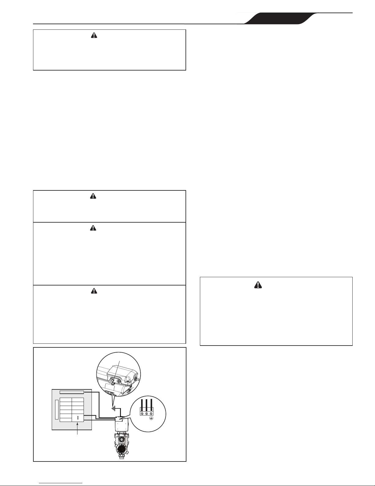
GROUND
NEUTRAL
Breaker Panel
GFCI
Pump
L1
L2
Terminal Block
Bonding Lug
Figure 4. Bonding the Motor
3.2.3 Electrical Wiring
1. The pump motor must be securely and adequately
grounded using the green screw provided. Ground
before attempting to connect to an electrical power
supply. Do not ground to a gas supply line.
2. Wire size must be adequate to minimize a voltage
drop during the start-up and operation of the pump.
3. Insulate all connections carefully to prevent
grounding or short-circuits. Sharp edges on
terminals require extra protection. For safety,
and to prevent entry of contaminants, reinstall all
conduit and terminal box covers. Do not force
connections into the conduit box.
3.2.4 Controller Options
The pump can be operated by one (1) of four (4)
controllers, JEP-R variable-speed controller, AquaLink RS,
AquaLink PDA or AquaLink Z4.
The pump communicates with the controllers via a four-
wire RS-485 interface.
NOTE Since the pump is operated by an external
controller the pump will not be turned on until it
is turned on with a controller.
3.2.4.1 Install with AquaLink®controller
The VS PlusHP pump can be operated by the following
AquaLink Controllers:
• AquaLink RS (Rev O or later)
• AquaLink PDA (Rev 4.0 or later)
• AquaLink Z4
1. Disconnect the high voltage lines or open any
breaker to which the pump power is connected.
WARNING
ELECTRICAL SHOCK HAZARD
Turn off all switches and the main breaker in
the variable-speed pump electrical circuit before
starting the procedure. Failure to comply may
cause a shock hazard resulting in severe personal
injury or death.
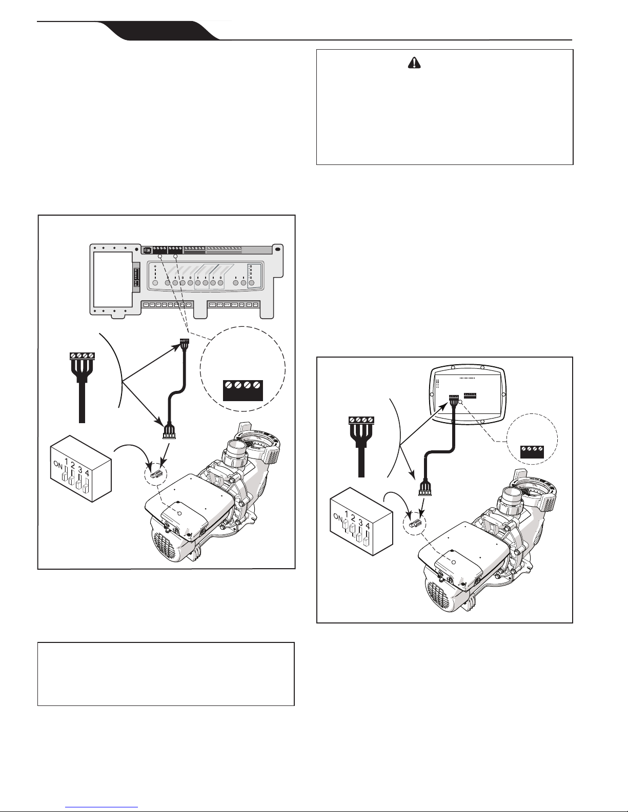
2. Dip switches 1 and 2 need to be in the OFF
position. See “Figure 5. Wiring AquaLink RS,
PDA or Z4”.
3. Select the desired address(es) by setting dip
switches 3 and/or 4, as shown in “Table 2. Dip
Switch Settings”
4. Disconnect the RS-485 cable from the 4-pin
header on the pump drive.
NOTE: Do not cut the cable or you will lose the ability to
returntothedefaultfactoryconguration
5. Connect the new RS-485 cable from the AquaLink
through the available compression tting and
route the 4-conductor cable through the motor
drive threaded port closest to the connector. See
““Figure 5. Wiring AquaLink RS, PDA or Z4”

Page 10 ENGLISH Jandy®Pro Series VS PlusHP Pumps |Installation & Operation Manual
6. Connect the other end of the cable to an RS-485
connector on the AquaLink RS (or multiplexer
interface board), matching wire colors with
connector positions See “Figure 5. Wiring
AquaLink RS, PDA or Z4”
7. Restore power to the pump and verify the
operation of the controller.
8. Refer to the appropriate manual for set up and
operation of the pump:
• AquaLink RS Manual #6593
• AquaLink PDA Manual #H0572300
• AquaLink Z4 Manual #H0386600.
Variable-Speed
Pump
4321
RED
BLACK
YELLOW
GREEN
RS485
Cable (22 AWG)
BLACK
YELLOW
RED
GREEN
Connect to AquaLink RS RS-485 Connector
(or Multiplexer Interface Board)
S1
S2
RESET
SERVICE
TIME OUT
FILTERPUMP
AUX 1
AUX 2
AUX 3
AUX 4
AUX 5
AUX 6
AUX 7
RS6 & RS8 ONLY
RS8 ONLY
HEATER SOLAR
POOL MODE
SPAMODE
SPADRAIN
SPAFILL
AUTO
654321
10 987654321
4321 4321
4-Position
DIP Switch
4321
BLACK
YELLOW
RED
GREEN
Figure 5. Wiring AquaLink RS, PDA or Z4
3.2.4.2 Install with JEP-R variable-speed
controller
IMPORTANT
The installer must TURN ON switches 1 and 2 at the
VS-FHP2.0 pump when connected to the variable-
speed controller.
1. Disconnect the high voltage lines or open any
breaker to which the pump power is connected.
WARNING
ELECTRICAL SHOCK HAZARD
Turn off all switches and the main breaker in
the variable-speed pump electrical circuit before
starting the procedure. Failure to comply may
cause a shock hazard resulting in severe personal
injury or death.
2. Remove the junction box cover and feed the
RS-485 cable into the tting.
3. Unplug the RS-485 connector.
4. Attach the four (4) RS-485 cable wires to the
RS-485 connector. Match the wire colors with the
positions on the connector: See “Figure 6. Wiring
JEP-R VSP Controller”
5. Insert the RS-485 connector back into the junction
box.
6. Dip switches 1 and 2 must be in the ON position,
and switches 3 and 4 must be in the OFF position.
See “Figure 6. Wiring JEP-R VSP Controller”
BLACK
YELLOW
RED
GREEN
RS485 4321
RED
BLACK
YELLOW
GREEN
REMOTE CONTROL
54321
INPUT 2
INPUT 3
INPUT 4
COMMON
INPUT 1
4-Position
DIP Switch
Variable-Speed
Pump
Controller
(Rear View)
RS485
Cable (22 AWG)
4321
BLACK
YELLOW
RED
GREEN
Figure 6. Wiring JEP-R VSP Controller
7. Connect the other end of the cable to the
controller. Match the colors of the wires with the
appropriate connector positions. See “Figure 6.
Wiring JEP-R VSP Controller”
8. Restore power and verify the operation of the
controller.
9. Refer to the Variable-Speed Controller Owner’s
Manual, H0412200, to operate the pump.

Page 11
ENGLISH
Jandy®Pro Series VS PlusHP Pumps |Installation & Operation Manual
3.2.4.3 Pump Dip Switch Settings
As shown in Figures 5 and 6 the 4 position dip switch
serves two (2) functions: it selects the pump address,
and it determines what type of controller will be used
with the pump.
Table 2. Dip Switch Settings
Switch 1 Switch 2 Controller
OFF OFF Factory Default
OFF OFF AquaLink®RS,AquaLinkPDA,
orAquaLinkZ4
ON ON Variable Speed Controller
Switch 3 Switch 4 Pump Address
OFF OFF PUMP1(FactoryDefault)
ON OFF PUMP 2
OFF ON PUMP 3
ON ON PUMP 4
3.2.5 Auxiliary Load Operation
The VS PlusHP is equipped with a terminal bar that
provides user access to a built-in Auxiliary Load relay
contact. This normally-open, dry contact is activated
under certain operating conditions and is primarily
intended to be used to control external devices that
require system water ow for proper functioning, such
as heaters, booster pumps, salt water chlorinators, etc.
See Figures 5 and 6 for compartment’s location details.
An access cover with Phillips-head screw must be
removed before proceeding.
3.2.5.1 Auxiliary Load Connection
Requirements
WARNING
ELECTRICAL SHOCK HAZARD
Due to the potential risk of fire, electric shock, or injuries
topersons,Zodiac®Pumps and any auxiliary loads must
be installed in accordance with the National Electrical
Code®(NEC®),alllocalelectricalandsafetycodes,and
theoccupationalSafetyandHealthAct(OSHA).Copies
of the NEC may be ordered from the National Protection
Association,470AtlanticAve.,Boston,MA02210,or
from your local government inspection agency.
In Canada, Zodiac Pumps must be installed in
accordancewiththeCanadianElectricalCode(CEC).
• THE Auxiliary Load relay contacts are rated at
230V/11ARMS.Pleaseensuretherequirementsof
theequipmenttobeconnectedtotheAuxiliaryLoad
do not exceed this rating.
EXAMPLE ONLY
NOT Representative of
all wiring configurations
EXAMPLE ONLY
NOT Representative of
all wiring configurations
Figure 7. 230V Auxiliary Load, Separate Power Sources
Wiring Diagram
F1015 F1014
TP133
TP130
TP127
/100
For
Controller
1 2
230V
Auxiliary
Load
GFCI-
Protected
230V
Power
Source 1
L2 L1 L1
(Black)
L2
(Red or
Black)
Earth
Earth
GFCI-
Protected
230V
Power
Source 2 Line
(Black)
L1
(Black)
L2
(Red or Black)
Note: Recommended Wiring Configuration
Figure 8. 115V Auxiliary Load, Separate Power Sources
Wiring Diagram
F1015 F1014
TP133
TP130
TP127
/100
For
Controller
1 2
115V
Auxiliary
Load
GFCI-
Protected
230V
Power
Source
L2 L1 L1
(Black)
L2
(Red or
Black)
Earth
Earth
GFCI-
Protected
115V
Power
Source Line
(Black)
Line
(Black)
Neutral
(White)
3.2.6 Auxiliary Load Operation
Characteristics
Auxiliary Load relay contact activation is speed-
dependent, and behaves as follows:
3.2.6.1 Contact Closure
From a stopped condition, there is a three-minute delay
before the Auxiliary Load contact is closed when the
motor speed reaches and maintains a speed of at least
1725 RPM.
From a running condition at below 1725 RPM, there is
a ve-second delay before the Auxiliary Load contact
is closed when the motor speed reaches and maintains a
speed of at least 1725 RPM.

Page 12 ENGLISH Jandy®Pro Series VS PlusHP Pumps |Installation & Operation Manual
3.2.6.2 Contact Opening
If the pump speed is below 1725 RPM, the Auxiliary
Load contact is opened. Contact openings are always
immediate.
Section 4. Operation
4.1 Remove Pump Lid
1. Make sure that the pump is turned off.
2. Make sure that the switch to the circuit breaker
that powers the pump motor is turned off.
WARNING
ELECTRICAL SHOCK HAZARD
Turn off all switches and the main breaker in
the variable-speed pump electrical circuit before
starting the procedure. Failure to comply may
cause a shock hazard resulting in severe personal
injury or death.
Rotate locking ring
counter clockwise
Align START
with port
Figure 9. Disengage Lock Ring
Locking Ring
Lid
Seal
Basket
Lift locking ring to
remove lid with seal
Figure 10. Remove Pump Lid
WARNING
ELECTRICAL SHOCK HAZARD
Due to the potential risk of fire, electric shock, or injuries
topersons,Zodiac®Pumps and any auxiliary loads must
be installed in accordance with the National Electrical
Code®(NEC®),alllocalelectricalandsafetycodes,and
theoccupationalSafetyandHealthAct(OSHA).Copies
of the NEC may be ordered from the National Protection
Association,470AtlanticAve.,Boston,MA02210,or
from your local government inspection agency.
In Canada, Zodiac Pumps must be installed in
accordancewiththeCanadianElectricalCode(CEC).
3. Make sure all necessary isolation valves are closed
to prevent pool water from reaching the pump. If
the pump is installed below water level, ensure all
necessary isolation valves are closed to prevent
pool water from reaching the pump.
4. Turn the locking ring counter-clockwise until
the ‘START’ markings align with the ports. See
Figure “Figure 9. Disengage Lock Ring”
5. Carefully lift to remove the lid with locking ring.

Page 13
ENGLISH
Jandy®Pro Series VS PlusHP Pumps |Installation & Operation Manual
4.2 Conduct Pressure Test
WARNING
When pressure testing a system with water, air is often
trapped in the system during the filling process. This air
will compress when the system is pressurized. Should
the system fail, this trapped air can propel debris at a
high speed and cause injury. Every effort to remove
trapped air must be taken, including opening the bleed
valve on the filter and loosening the pump basket lid
while filling the pump.
WARNING
Trapped air in the system can cause the filter lid
to be blown off, which can result in death, serious
injury, or property damage. Be sure all air is properly
purged out of the system before operating. DO NOT
USE COMPRESSED AIR TO PRESSURE TEST OR
CHECKFORLEAKS.
WARNING
ELECTRICAL SHOCK HAZARD
Do not pressure test above 35 PSI. Pressure testing
must be done by a trained pool professional. Circulation
equipmentthatisnottestedproperlymightfail,which
could result in severe injury or property damage.
WARNING
When pressure testing the system with water, it is very
important to make sure that the pump basket lid is
completely secure.
1. Fill the system with water, being careful to
eliminate trapped air.
2. Pressurize the system with water to no more than
35 PSI.
3. Close the valve to trap pressurized water in the
system.
4. Carefully observe the system for leaks and/or
pressure decay.
4.3 Start-up
WARNING
To avoid risk of property damage, severe personal
injury or death, verify that all power is turned off before
starting this procedure.
If this is a new pool installation, make sure all piping
is clear of construction debris and has been properly
pressure tested. Check the lter for proper installation,
verifying that all connections and clamps are secure
according to the manufacturer’s recommendations.
CAUTION
Never run the pump without water. Running the
pump “dry” for any length of time can cause severe
damage to both the pump and motor and will void the
warranty.
1. Release all pressure from the system and open the
lter pressure release valve.
*
Open pressure relief valve
When all air has been purged
there will be a water discharge.
Pressure relief valve displayed is typical for
Jandy Cartridge Filters. Be sure to check with
your filter manufacturer if the pressure relief
valve on your filter differs from the one displayed.
*
Figure 11. Purge Air from system
2. Take one of the following actions:
a. If the pump is located below the water level of
the pool, open the lter pressure release valve
to prime the pump with water.
b. If the pump is located above the water level,
remove the lid and ll the basket with water
before starting the pump.
3. Prior to replacing the lid, check for debris around
the lid o-ring seat. Debris around the lid o-ring
seat will cause air to leak into the system, and
make it dif cult to prime the pump.
4. Hand-tighten the lid to make an air tight seal. Do
not use any tools to tighten the lid: hand-tighten
only. Ensure that the lid is secure. Make sure all
valves are open and the unions are tight.
5. Restore power to the pump and then turn it on.
6. Once all the air has left the lter, close the lter
pressure release valve.
7. The pump should prime. The time it takes to
prime will depend on the elevation and length of
pipe used on the suction supply pipe. If the pump
does not prime and all the instructions to this point
have been followed, check for a suction leak. If
there is no leak, repeat Steps 2 through 7.
8. For technical assistance, call Zodiac®Technical
Support at 1.800.822.7933.

Page 14 ENGLISH Jandy®Pro Series VS PlusHP Pumps |Installation & Operation Manual
Section 5. Maintenance
5.1 Routine Maintenance
CAUTION
To avoid damage to the plastics, do not use lubricant
or sealant on the o-ring. Only soapy water should be
used to install and lubricate the o-ring.
Inspect the pump basket for debris by looking through
the clear pump lid. As debris accumulates, it will begin
to block the ow of water through the pump. Keep the
basket clean to improve the performance of the pump.
1. Turn off the power to the pump. If the pump is
located below the water level, close the isolation
valves on the suction and discharge sides of the
pump to prevent back ow of water.
2. Turn the lid’s locking ring counter-clockwise until
‘START’ aligns with the ports. Carefully remove
the lid.
CAUTION
A misaligned basket will cause the lid to be improperly
seated, allowing an air leak, which could result in pump
damage.
3. Lift the basket out of the pump. Dispose of all
debris and thoroughly clean the basket, making
sure all the holes are open. Using a garden hose,
spray the basket from the outside to help clear the
holes. Remove any remaining debris by hand.
4. Replace the basket in the pump by aligning the
open section of the basket with the inlet pipe. If
aligned properly, the basket will drop easily into
place. Do not force it into place.
5. Remove the lid o-ring and remove debris around
the lid o-ring seat, as this will cause air leaks into
the system. Clean the lid o-ring and replace it.
NOTE Make sure the lid seal is correctly oriented.
Ensure proper seal orientation
when replacing the lid
Figure 12. Replace Lid and Seal
6. Replace the lid with locking ring on the pump
housing. Align ‘START’ with the ports and turn
the lid’s locking ring clockwise until ‘LOCKED’
aligns with the ports. Hand-tighten the lid to
make an air tight seal. Do not use any tools to
tighten the lid.
7. Verify that all valves have been returned to the
proper position for normal operation.
8. Open the pressure release valve on the lter, and
make sure it is clean and ready for operation.
9. Turn on the power to the pump. Once all the air
has been evacuated from the lter, close the lter
pressure release valve.
5.2 Winterizing the Pump
CAUTION
The pump must be protected when freezing
temperatures are expected. Allowing the pump to
freeze will cause severe damage and void the warranty.
CAUTION
Do not use antifreeze solutions in the pool, spa, or
hot tub systems! Antifreeze is highly toxic and may
damage the circulation system. The only exception to
this is Propylene Glycol. For more information, see
yourlocalpool/spasupplystoreorcontactaqualified
swimming pool service company.
1. Drain all water from the pump, system equipment,
and piping.
2. Remove the two (2) drain plugs. Store the drain
plugs in a safe location and reinstall them when
the cold weather season is over. Do not lose the
o-rings.
3. Keep the motor covered and dry. Do not cover it
with plastic, as this will create condensation and
this moisture will damage the pump.
NOTE Toprotectyourpump,ZodiacPoolSystems
LLCrecommendshavingaqualiedservice
technician or electrician properly disconnect
the electrical wiring at the switch or junction
box.Oncethepowerisremoved,thetwo(2)
unions can be loosened and the pump stored
indoors. For safety, and to prevent entry of
contaminants, reinstall all conduit and terminal
box covers.
4. When the system is reopened for operation, make
sure all piping, valves, wiring, and equipment
are in accordance with the manufacturer’s
recommendations. Pay close attention to the lter
and electrical connections.
5. The pump must be primed prior to starting; refer
to “4.3 Start-up”

Page 15
ENGLISH
Jandy®Pro Series VS PlusHP Pumps |Installation & Operation Manual
Section 6. Troubleshooting and Repair
Zodiac® strongly recommends that you call a qualied service technician to perform any repairs on the lter/pump
system. To locate a qualied technician, check your local yellow pages or visit www.zodiacpoolsystems.com
or www.zodiacpoolsystems.ca and click on “Dealer Locator.”
Symptom Possible Cause/Solution
Reduced flow
being returned
to pool and/or
less water being
pulled in by
skimmer.
Verify that skimmer baskets, pump basket and other screens are clean. Clean as necessary.
Check filter and clean as necessary.
Check valve positions. Adjust as necessary.
NOTEMultiplepiecesofequipmentoperatingatonetime(forexample,waterfalls,spajets,andsurface
returns)willaffecttheproperoperationofthecleaningsystem.
Check the cleaning system manual to ensure that the system is adjusted according to the manufacturer's
recommendations.
Bubbles are
present in the
pump basket.
Air is in the system. Check the pool or spa water level to ensure that it is at the proper level and air is not
being drawn into the suction piping. If the water is at the normal level, turn off the pump. Turn the lid's locking
ring counter-clockwise until 'START' aligns with the ports. Remove the lid and check for debris around the
lid seal seat OR improper installation of the lid seal, as either condition will allow air to leak into the system.
Clean the lid seal and replace it on the lid. Replace the lid on the pump housing. Align 'START' with the ports
andturnthelockingringclockwiseuntil'LOCKED'alignswiththeports.Hand-tighten the lid to make an air-
tight seal. Do not use any tools to tighten the lid. Turn the pump back on.
Air leaks are still
present.
Check the suction side piping union. While the pump is running, try to tighten the union. If this does not stop
the air leak, turn off the pump. Loosen both unions and slide the pump out of the way. Remove, clean, and
re-install both union o-rings.
Reposition the pump next to the piping and secure the union nuts to the pump. With clean union o-rings,
hand-tightening of the unions should create a seal. If the unions still do not seal, gently tighten with a large
pair of tongue-and-groove pliers.
Do not over-tighten.
There is no air in
the system, but
the pressure is
still low.
It is possible that debris is caught in the pump impeller. The pump impeller moves the water, and the vanes in the
impeller can become blocked with debris.
There is no debris
blocking the
impeller and the
pressure is still
low.
Thepumpimpelleranddiffuserareshowingsignsofnormalwear.Haveaqualifiedservicetechniciancheck
the impeller and diffuser and replace as necessary.
Ifthepumpispartofarelativelynewinstallation,itcouldbeanelectricalproblem.Contactaqualified
service technician. Have the technician check for loose electrical connections and check the voltage at the
pumpmotorwhileitisinoperation.Thevoltagemustbewithin10%ofthemotor'sdataplaterating.Ifthe
voltageisnotwithin10%,contactaqualifiedelectricianand/orthelocalpowerserviceprovider.
Pumpsealisleakingair.Haveaqualifiedservicetechnicianreplacetheseal.
The pump is
leaking water
between the
motor and pump
body.
This is caused by a damaged or failed mechanical seal. Replace the seal.
The pump gets
hot and shuts off
periodically.
Makesurethatthereisadequateroomaroundthemotortocirculateairandkeepthemotorcool.Have
aqualifiedelectriciancheckforlooseconnectionsandcheckthevoltageatthepumpmotorwhileitisin
operation.Thevoltagemustbewithin10%ofthemotor'sdataplaterating.Ifthevoltageisnotwithin10%,
contactaqualifiedelectricianand/orthelocalpowerserviceprovider.
Pump will not
start.
No power to pump.
Make sure pump is properly connected to high voltage. See “3.2 Electrical Installation”
Improper low-voltage wiring.
Check low-voltage wiring between pump and controller. Correct if necessary. See “3.2 Electrical Installation”
Improper pump address setting.
Make sure that pump dip switches 3 and 4 are set properly for the installation. Both should be OFF for use
withVariable-SpeedControllerorsettotheproperaddresswhenconnectedtoanAquaLink® RS controller,
anAquaLink PDA,oranAquaLinkZ4.See“3.2.4.1 Install with AquaLink® controller”
Fault condition exists.
View fault message on controller and correct fault before proceeding. If unsure how to correct fault, contact
Zodiac®TechnicalSupportat800.822.7933.

Page 16 ENGLISH Jandy®Pro Series VS PlusHP Pumps |Installation & Operation Manual
Symptom Possible Cause/Solution
Variable-Speed
Controller LCD
is not displaying
information
or
pump LEDs are
not illuminated.
Incorrect dip switch setting.
Make sure pump dip switches 1 and 2 are both ON if the controller is the JEP-R and both are OFF if the
controllerisaPDA,AquaLinkRS,orAquaLinkZ4.See“3.2.4.1 Install with AquaLink® controller”
Improper low-voltage wiring.
Check low-voltage wiring between pump and controller. Correct if necessary. See “3.2 Electrical Installation”
Controller
displays “Pump
not connected”.
Improper low-voltage wiring.
Check low-voltage wiring between pump and controller. Correct if necessary. See “3.2 Electrical Installation”
Improper pump address set.
Ensure pump dip switches 3 and 4 are set properly for the installation. Both should be OFF for use with
Variable-SpeedControllerorsettotheproperaddresswhenconnectedtoanAquaLink RS,AquaLinkPDA,
oranAquaLinkZ4.See“3.2.4.1 Install with AquaLink® controller”
Fault message
appears on
controller display.
Fault condition exists.
View fault message on controller and correct fault before proceeding. If unsure how to correct fault, contact
ZodiacTechnicalSupportat800.822.7933.

Page 17
ENGLISH
Jandy®Pro Series VS PlusHP Pumps |Installation & Operation Manual
Section 7. Product Speci cations and Technical Data
7.1 Replacement Parts List
To order or purchase parts for Zodiac®pumps, contact your nearest Zodiac dealer. If the Zodiac dealer cannot
supply you with what you need, contact Zodiac technical support at 1.800.822.7933, or send an e-mail message to
Key
No. Description
Order
Part No.
1 Motor, Drive R0562201
2MotorHardwareKit R0446700
3CoverFan,GENIIReplacementKit(Hardware,
Cover) R0562400
4 Hardware Speed Drive, GEN II R0562500
5Connector,SpeedDrive,(4-PinConnector) R0660900
6Cable,RS-485,ReplacementKit* R0535100
7 Cover, Large, Speed Drive w/Gasket, GEN II R0562300
8 Data Cable, Feed Thru R0501100
9ImpellerReplacementKit R0807200
10 Diffuser w/O-ring & Hardware R0445400
11 MechanicalSeal(CarbonandCeramic) R0479400
12 Pump Body R0448700
Key
No. Description
Order
Part No.
13 Motor Mounting Foot Assembly w/Screws R0445700
14 Locking Ring w/Lid & Seal R0448800
15 Pump Debris Filter Basket R0448900
16 Drain Plug w/O-ring R0446000
17 Tail Piece (2” x 2½”)w/O-ring&CouplingNut(Set
of2)
R0449000
18 LidSealandLidO-ring(LidO-ringNotShown) R0449100
19 BackplateKitw/HardwareandMechanicalseal R0445200
20 O-ring, Backplate R0446300
21 O-ring, Tail Piece R0449200
22 Diffuser/Impeller w/O-rings & Mounting Hardware R0446500
23 Backplate Bolts & Washers R0446600
24 Screws, Motor Mounting Foot R0446800
7.2 Exploded View
1,2
1,3
1,4
1,5
6
1,7 8
10
10, 22
9
11,19
13 24
12
15
14
18,14
19
19,20
17
17,21
17,21
17
16
23

Page 18 ENGLISH Jandy®Pro Series VS PlusHP Pumps |Installation & Operation Manual
7.3 Performance Curves
0
5
10
15
20
25
30
35
40
0
10
20
30
40
50
60
70
80
90
100
0 20 40 60 80 100 120 140
PSI
Total Dynamic Head (Feet of Water)
Flow Rate, Gallons Per Minute (GPM)
VSPHP270 Series Pump Performance Curves
3450 RPM
2750 RPM
1730 RPM
1000 RPM
CURVE "A"
CURVE "C"
CURVE "B"
7.4 Physical and Operational Speci cations
7.4.1 Pump Speci cations
Model No. HP Voltage Max Watts Pipe Size Carton Weight Overall Length 'A'
VSPHP270 0.25-2.7 230VAC 2,250W 2½ - 3” 50lbs. 303/8"
7.4.3 PHP Pump Dimensions
9 1/8"
(232 mm)
8 7/8"
(226 mm)
9"
(229 mm)
31"
(788 mm)
11 3/8"
(289 mm)
13 7/8"
(353 mm)
14 1/8"
(378 mm)
Bolt Holes, Center to Center Front Edge of Union
to Center of Bolt Holes

Page 19
ENGLISH
Jandy®Pro Series VS PlusHP Pumps |Installation & Operation Manual
NOTES

Zodiac Pool Systems LLC
2620 Commerce Way, Vista, CA 92081
1.800.822.7933 | www.ZodiacPoolSystems.com
©2017 Zodiac Pool Systems LLC. ZODIAC®is a registered trademark of Zodiac International, S.A.S.U.,
used under license. All trademarks referenced herein are the property of their respective owners.
H0490000 REVE
Certified to
NSF/ANSI Standard 50
CONFORMSTOULSTD1081
CERTIFIEDTOCSASTDC22.2NO108
This manual suits for next models
7
Table of contents
Other Jandy Water Pump manuals

Jandy
Jandy WFTR User manual

Jandy
Jandy JCP Series User manual

Jandy
Jandy ePump Series User manual

Jandy
Jandy SHPF User manual

Jandy
Jandy FHPM10 User manual

Jandy
Jandy Stealth SHPF.50 User manual

Jandy
Jandy ePump User manual

Jandy
Jandy VSFHP185DV2A User manual

Jandy
Jandy FHP Series User manual

Jandy
Jandy Stealth SHPM User manual
Popular Water Pump manuals by other brands

Ingersoll-Rand
Ingersoll-Rand ARO EVO EP20 Series Operator's manual

Levitronix
Levitronix BPS-4H Series user manual

Vaillant
Vaillant climaVAIR plus manual

Hamworthy
Hamworthy Trigon ST1 Installation, Commissioning, Operation & Service Instructions

Vivaria
Vivaria Vario N-1000 operating instructions

Kripsol
Kripsol KNG user guide