PowerToStore
6
www.janitza.com
REFERENCE
·The external energy supply must be connected to a circuit with an own, specially marked
fuse (16A).
·From this fusing up to the supply point of the low voltage side of the electrical mains (house
connection box) it may be fused only one another time.
·It must be excluded, that the circuit tot he external energy supply is interrupted because of
the switch off of other means of production.
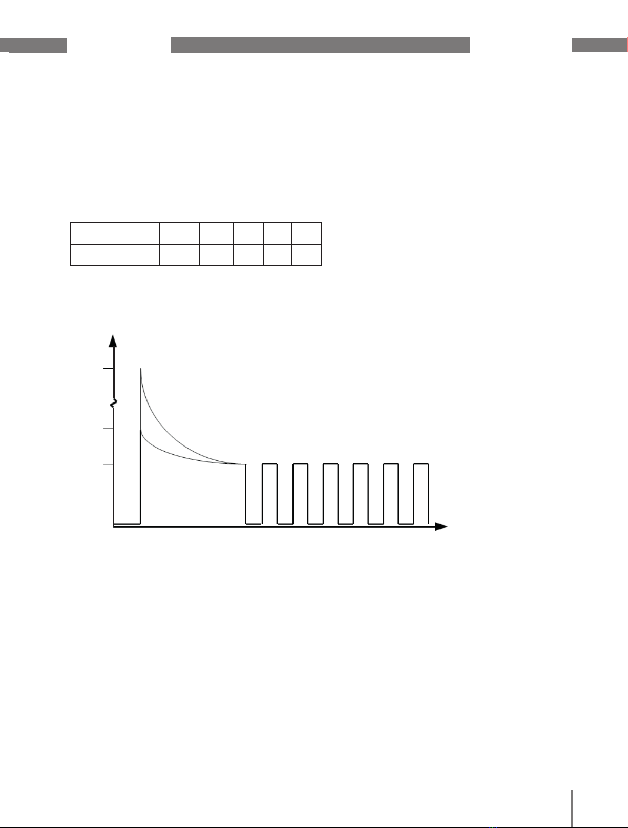
REFERENCE
·In case of overload the DC output current is composed of the maximum current of the DC –
DC converter as well as of the current of the AC – DC converter. The output circuit must be
fused externally to avoid an overload!
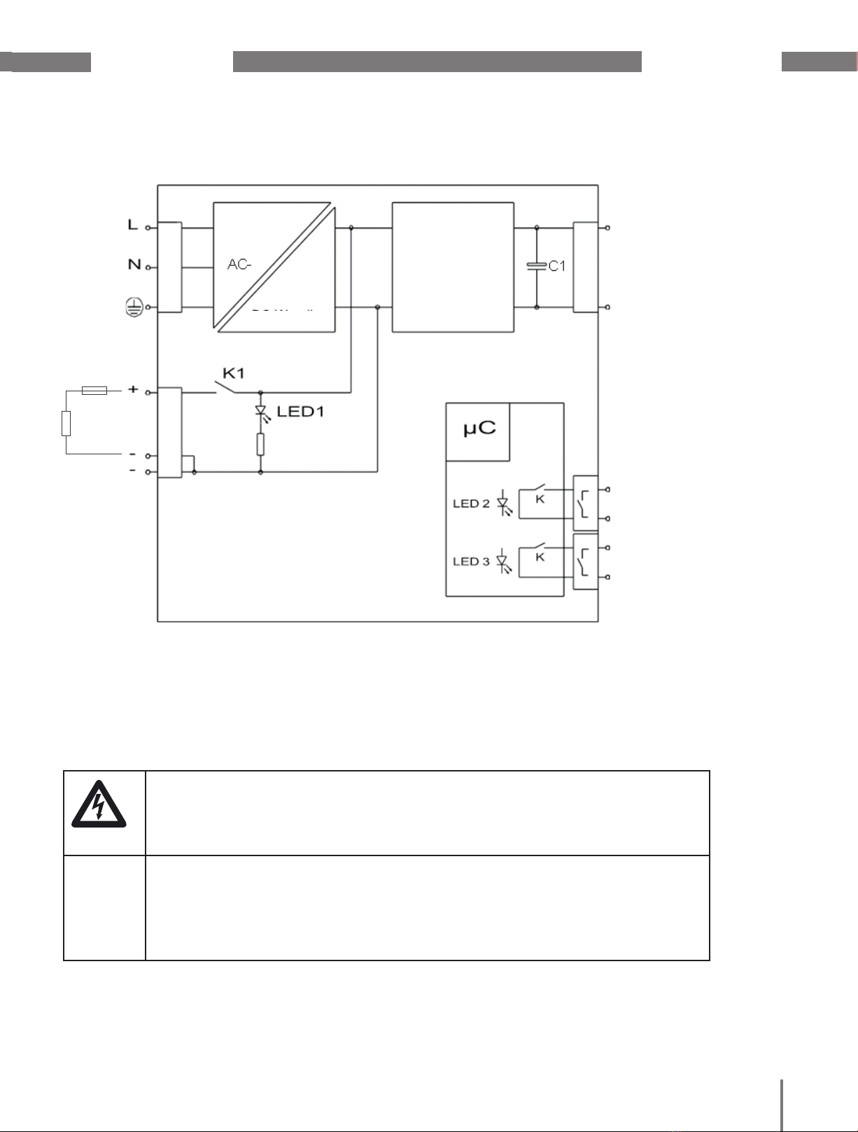
DANGER
·The unit is prepared for protective system I (protective earthing).
·The operational earth must absolutely be connected. In case of non-observance touchable
parts could carry voltage in case of error. Danger of fatal electric shock.
3.3 Connection
·Prior to connection, the values of the DC supply must be compared with the values on the type plate.
·Connection according to the designations of the connection terminals (see terminal allocation).
·Not used connection screws must be tightened.
·During connection of the load the polarity „+“ and „-“ must be respected.
·The mains voltage must be switched off and must be protected against switch-on by a third party.
·The voltage-free cable must be connected to the designated connection terminal. The mains phase
must be respected. The mains is connected at the terminals „L“, „N“ and PE ( ).
·The operational earth must absolutely be connected.
Dimension the cable cross-section of the supply and outlet lines according to EN 62368-1 Table G.5; see also
the table above.
The status of the external power supply can be transmitted to a subordinate power station. The contacts are
coupled with the corresponding LED displays. The illumination of a LED effects the activation of the corre-
sponding relay.
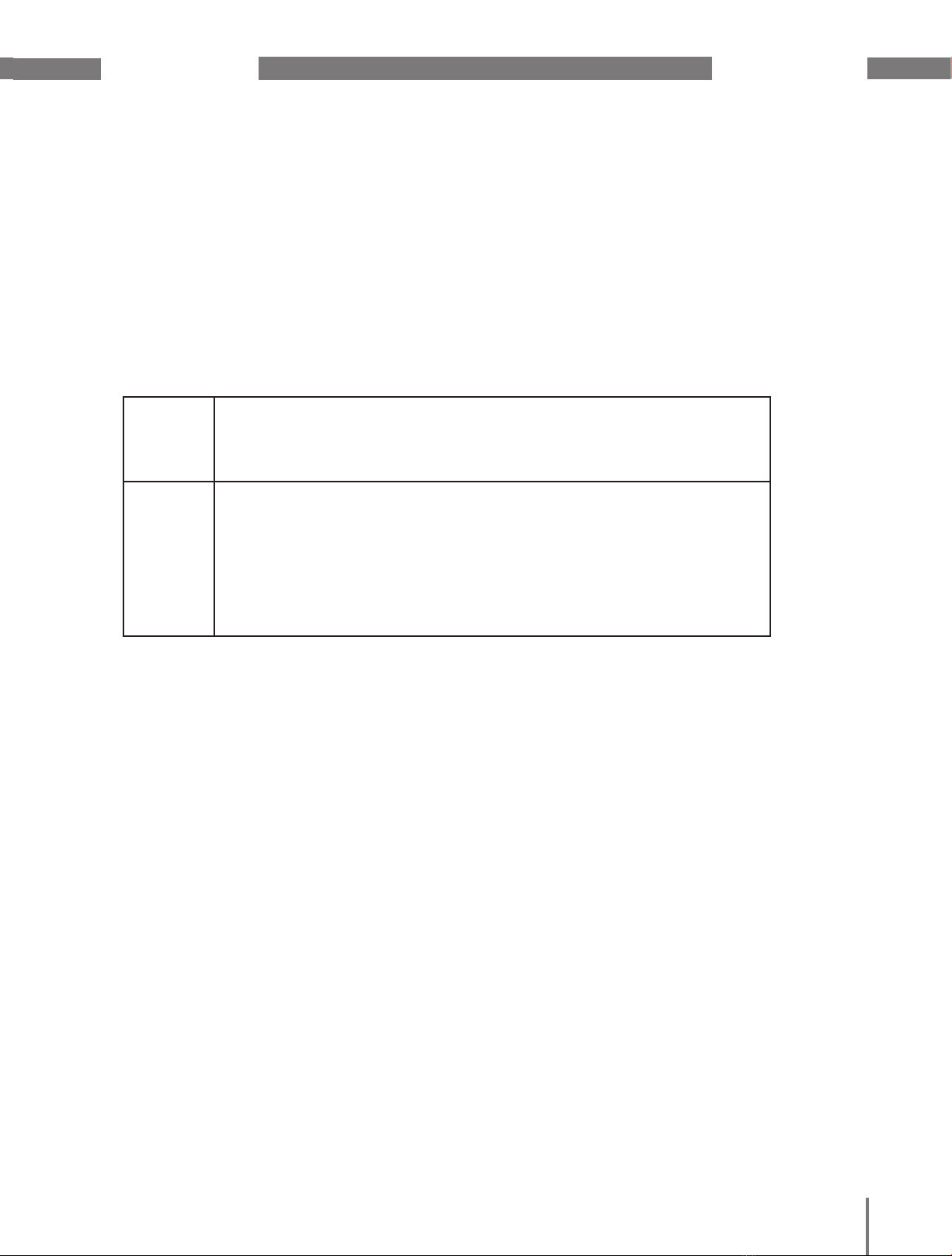
Terminals
Connection
Designation Max. torque Cable cross section
L, N, PE 0.4 Nm
(3.54 lbf in) 0.5 – 2.5 mm²
AWG 14 Input voltage
Ue / Vin o.K.
(4 = COM, 5 = NO) 0.4 Nm
(3.54 lbf in) 0.1 – 2.5 mm²
AWG 14
Signal contact
Ue / Vin o.K. Maximum contact load:
30 V DC/0.5 A
(potential-free relay con-
tact)
UC / Vcap. >
(6 = COM, 7 = NO) Signal contact
UC / Vcap. >
+ C / cap. – C / cap. 0.4 Nm
(3.54 lbf in) 0.5 – 2.5 mm²
AWG 14
CEM-module
+ Ua / Vout. – Ua / Vout. Consumer
CC
CC