Janome DC6030 User manual

DC6030
SERVICE MANUAL

What to do when......................................................................................................... 1-2
Changing External Parts (1) (Face Cover) .................................................................... 3
Changing External Parts (2) (Free-arm Cover).............................................................. 4
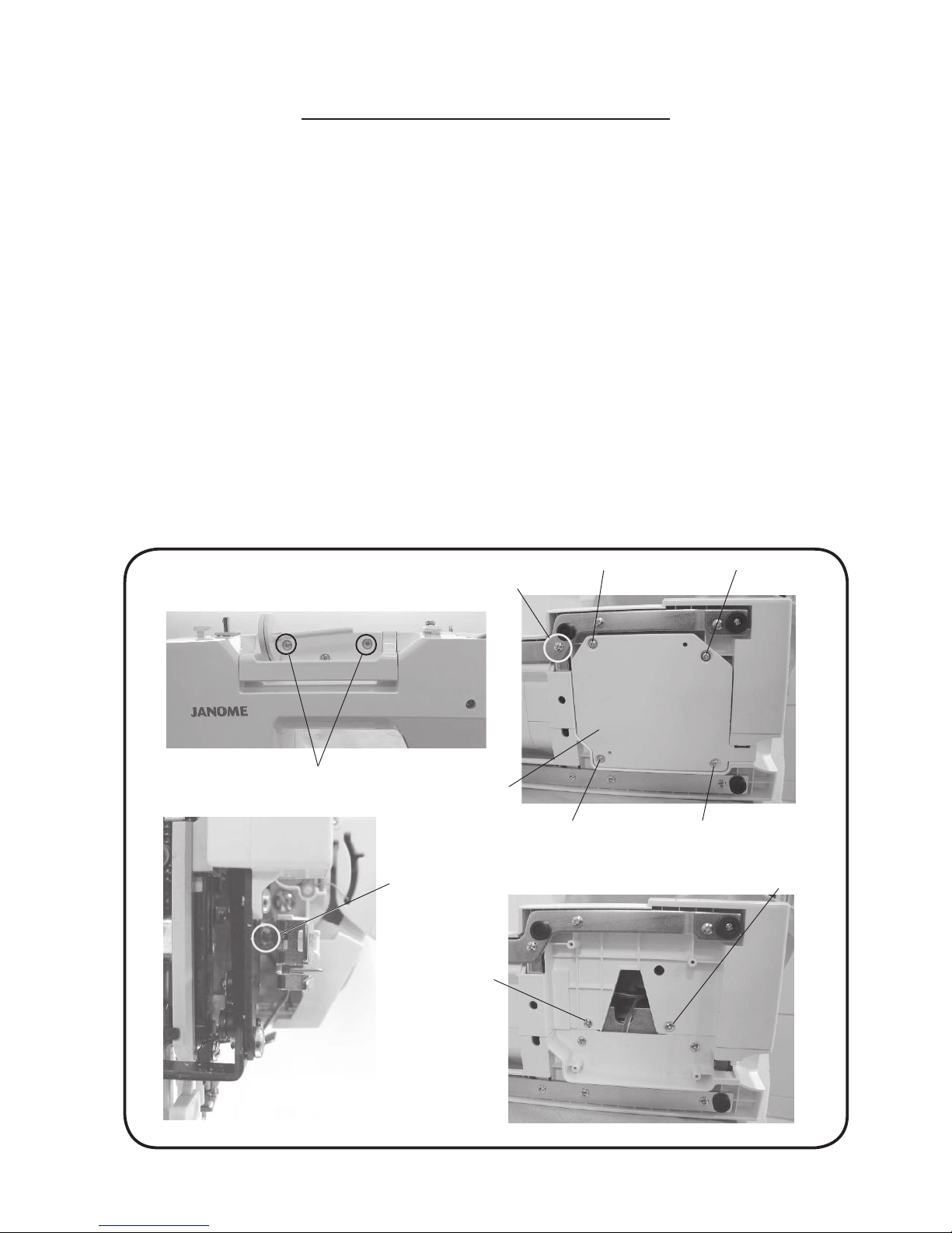
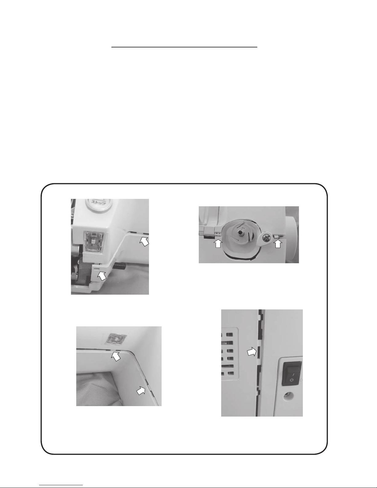
Changing External Parts (3-1) (Front Cover)................................................................. 5
Changing External Parts (3-2) (Front Cover)................................................................. 6
Changing External Parts (4) (Rear Cover) .................................................................... 7
Presser Bar Height ........................................................................................................ 8
Needle Drop Position..................................................................................................... 9
Adjustment of Hook Timing.......................................................................................... 10
Adjustment of Needle Bar Height ................................................................................ 11
Clearance between Needle and Tip of Hook Rotary ................................................... 12
Feed Dog Height ......................................................................................................... 13
Feed Dog Adjustment.................................................................................................. 14
Top Tension.................................................................................................................. 15
Circuit Board A connection.......................................................................................... 16
Self-diagnostic Test ................................................................................................ 17-22
To Display the Version of the Program......................................................................... 22
Replacing the Circuit Board A ..................................................................................... 23
Replacing the Circuit Board F, F2, L1, L2 and Speed Control Slider........................... 24
Replacing the Driving Motor ........................................................................................ 25
Replacing the Switching Regulator unit....................................................................... 26
Adjustment of Buttonhole Lever Position..................................................................... 27
Adjustment of Needle Threader Plate.......................................................................... 28
Replacing thte Bobbin Thread Holder/Cutter unit ........................................................ 29
Cleaning area of Thread Cutter and Lower Shaft Gear ............................................... 30
INDEX

1
What to do when
1. Needle is not inserted properly.
2. Needle is bent or worn.
3. Incorrectly threaded.
4.Needle or thread are inappropriate for the
fabric being sewn.
5. Sewing on stretch fabric.
6. Inappropriate needle bar height.
7. Inappropriate needle to hook timing.
8. Inappropriate needle to hook clearance.
Insert the needle properly.
Change the needle.
Rethread.
Use the recommended sewing needle
and thread.
Use a HA x #11 blue tip needle.
See mechanical adjustment “Needle bar
height”. (Reference P.11)
See mechanical adjustment “Adjustment
of hook timing”. (Reference P.10)
See mechanical adjustment “Clearance
between needle and tip of the rotary
hook”. (Reference P.12)
1. Incorrect feed dog height.
2. Feed dog is in down position.
3.Thread on bottom side of fabric is jammed
up.
4. Feed dog teeth are worn.
Adjustment of Feed Dog Height.
(Reference P.13)
Raise the feed dog.
Make sure to bring both needle and bobbin
threads under the foot when start sewing.
Change the feed dog.
Condition Cause How to x
Skipping
Stitches
Fabric not
moving
1. Thread path is incorrect.
2. Needle is bent or dull.
3. Top tension is too strong.
4. Needle size is inappropriate for fabric.
5. Needle eye is worn.
6. Needle hole in needle plate is worn or
burred.
Use the proper thread path.
Replace with a new needle.
Adjust top tension correctly.
Use appropriate needle for fabric and
thread in use.
Change the needle.
Repair the hole or replace the needle
plate.
Breaking
upper thread.

2
1. Bobbin holder is incorrectly threaded.
2. Too much thread is wound on the bobbin.
3. Lint is stuck inside the bobbin holder.
4. Thread quality is too low.
5. Thread is jamming around the bobbin
holder.
1. Needle is hitting the needle plate.
2. Needle is bent or worn.
3. Needle is hitting the hook.
4. Fabric is being pulled too strongly while
sewing.
Set the bobbin thread correctly.
Adjust the position of bobbin winder
stopper.
Clean the bobbin holder.
Change to a high quality sewing thread.
Clear out the jamming thread.
Adjustment of Needle Drop Position
(Reference P.9)
Change the needle.
Adjustment of Clearance between Needle
and Tip of Hook Rotary (Reference P.12)
Guide the fabric gently while sewing
Needle
breakes
Condition Cause How to Fix
1. Lower shaft gear is loose.
2. Inappropriatte belt tension.
3. Not enough oil.
4. Upper shaft gear is loose.
Eliminate the looseness.
See part removal and
replacement “driving motor (DC motor)”.
(Reference P.25)
Oil all moving parts.
Eliminate the looseness.
1. Top tension is too strong.
2. Inappropriate feed balance.
Adjustment of top tension.
Adjust the feed balancing screw.
Noisy
operation
Deformation
pattern

3
Face Cover
To remove:
1. Remove the setscrews (2 pcs.).
Remove the face plate.
To attach:
2. Follow the above procedure in reverse.
* Make sure that the face plate can be closed fitting with the thread tension and the rear cover.
Changing External Parts (1)
Setscrew
Face cover

4
Free-arm Cover
To remove:
1. Remove the cap and setscrew (A).
2. Remove the setscrew (B). Move the free-arm cover to the left. Remove the free-arm cover.
To attach:
3. Insert the free-arm cover
Tighten the setscrew (A) and (B).
4. Attach the cap.
Changing External Parts (2)
Setscrew (A)
Setscrew (B)
Free-arm cover
Cap

5
Changing External Parts (3-1)
Front Cover
To remove:
1. Remove the face cover.
2. Remove the setscrews (A) (2 pcs.).
3. Loosen the setscrew (B) (1 pcs.).
4. Remove the setscrews (C) (1 pcs.), setscrews (D) (4 pcs.),and back cover.
(Disconnect the connectors)
5. Remove the setscrews (E) (2 pcs.).
6. Remove the front-cover (Reference P.6), disconnect all the connectors from the circuit board A.
Notes:
Do not disconnect the connectors by pulling on cord.
To disconnect, grasp the connector, not the cord.
To attach:
1. Follow the above procedures in reverse.
Notes:
1. Make sure to insert the connector into the connector receptacle of the same color on the board.
2. Make sure to insert the connector in the correct direction pushing to snap it in place.
Setscrews (B)
Setscrews (D)
Setscrews (C)
Setscrews (D)
Back cover
Setscrews (A)
Setscrews (D)
Setscrews (D)
Setscrews (E)
Setscrews (E)

6
Changing External Parts (3-2)
Front Cover
1. Disengage the front cover and rear cover hooks.

7
Rear Cover
To remove:
1. Remove the free-arm cover.
2. Remove the setscrews (A) (5 pcs.).
3. Remove the setscrews (B) (4 pcs.) and back cover.
4. Remove the setscrews (C) (1 pcs.) and setscrews (D) (2 pcs.). Remove the rear cover.
Lower the presser foot lifter.
Remove the part around the presser foot lifter, and remove the part around the machine socket.
To attach:
5. Follow the above procedures in reverse.
Changing External Parts (4)
Setscrews (A)
Setscrews (A)
Setscrews (B)
Setscrews (B)
setscrews (C)
Back cover
Rear cover
Presser
foot lifter
Setscrews (A)
Setscrews (D) Setscrews (D)

8
The distance between the bottom of the presser foot in up position and the needle plate should be 6.0 mm.
Make sure that the presser foot should be parallel to the feed dog slots in the needle plate.
1. Remove the face plate.
2. Raise the presser foot and presser foot lifter and loosen the setscrew.
Place the 6mm spacer (block) between the presser foot and the needle plate.
Adjust the direction of the presser bar.
3. Tighten the setscrew firmly.
4. Attach the face plate.
Presser Bar Height
Presser foot lifter
Setscrew
Zigzag foot (A)
6.0 mm
Needle plate
Presser bar height
Direction of the presser bar
Should be
pararel
Feed dog
Slot
Block

9
Set the stitch pattern to “ ”. The standard needle drop position should be at center of the needle plate hole.
Select zigzag stitch “ ”, and set the stitch width at “5.0”.
The clearance between the needle and the edge of the needle hole in the needle plate should be at least
0.2 mm on either side. If not, adjust as follows:
1. Turn the power switch on. Set the stitch pattern to “ ”, and select zigzag stitch “ ”.
Check that the needle drop position.
2. If the needle drop position is not correct, turn the power switch off and remove the face cover.
Loosen the hexagonal socket screw 3 x 4. Adjust the needle drop position by turning the eccentric pin.
Note:
Make sure to adjust the eccentric pin between the range of downward direction.
3. Tighten the socket screw 3 x4.
Attach the face cover.
Note:
Check the hook timing after this adjustment.
Needle Drop Position
Eccentric pin
Socket screw 3 x 4
Needle hole
0.2 mm or more
0.2 mm or more
A=B
AB
Eccentric
Rotation center
Between the range of
downward direction

10
Lower shaft gear
Hexagonal socket screw
The amount of ascending travel of the needle bar from its lowest position to the position ( ) where the tip of the
rotary hook exactly meets the right side of the needle should be 3.25 to 3.55 mm.
1. Remove the needle plate and bobbin holder.
2. Remove the free-arm cover.
3. Turn the power switch on. Select the pattern (left position). Set the zigzag width at 0.
4. Turn the handwheel toward you to lower the needle at its lowest position.
5. Loosen the hexagonal socket screw (2 pcs.).
6. Move the needle bar 3.4 mm from the lowest position.
7. Turn the lower shaft gear until the tip of hook meets the right side of the needle while holding the handwheel.
8. Tighten the hexagonal socket screw (2 pcs.).
9. Attach the free-arm cover, bobbin holder and needle plate.
Adjustment of Hook Timing
Needle plate
Bobbin holder
Left position
(#14)
Tip of hook meets the
right side of the needle
Lowest needle position
3.25 – 3.55mm
Hexagonal socket screw

11
1.6 – 2.0 mm
Before proceeding with this adjustment, check the hook timing (refer to page 10).
The distance between the upper edge of the needle eye and the tip of the hook should be in the range of 1.6
to 2.0 mm when the tip of the hook timing meets right side of the needle in the left needle position ( ) as
the needle ascends from its lowest position.
1. Remove the needle plate, bobbin holder and face plate.
2. Turn the power switch on.
3. Select the pattern (left position). Set the zigzag width at 0.
4. Turn the handwheel toward you until the tip of hook meets the right side of the needle.
5. Loosen the hexagonal socket screw.
6. Move the needle bar to adjust the needle bar height, and tighten the hexagonal socket screw.
Be careful not to turn the needle bar.
7. Attach the bobbin holder, needle plate and face cover.
Adjustment of Needle Bar Height
Needle plate
Bobbin holder
Needle setting groove
Upper edge of
needle hole
Hook race (unit)
Hook race
Tip of hook meets the right side of the needle
Left position
(#14)
Hexagonal socket screw

12
Tip of hook
–0.1 to +0.05 mm
Clearance between Needle and Tip of Hook Rotary
The clearance between the needle and the point of hook should be –0.1 to +0.05 mm.
1. Remove the needle plate and bobbin holder. Attach the master needle. Turn the power switch on and
set the zigzag width at maximum.
2. Remove the face cover.
3. Loosen the setscrew (A) (2 pcs.).
4. Turn the handwheel toward you. Adjust the clearance between the needle and the tip of the rotarty
hook, by moving the hook base plate up or down, to within –0.1 to +0.05 mm at the left and right needle
position.
5. Tighten the setscrew A (2 pcs.).
6. Attach the face cover. Remove the master needle. Attach the bobbin holder and needle pate.
7. Check the clearance between the needle and the edge of the needle hole in the needle plate.
Needle plate
Bobbin holder
Needle bar supporter
adjusting plate Hexagonal socket screw (A)

13
The highest position of the feed dog should be between 0.80 and 0.90 mm from the surface of the needle
plate.
1. Remove the free-arm cover.
2. Lower the presser foot and turn the power switch on.
3. Turn the handwheel toward you to set the feed dog at the highest position.
4. Loosen the setscrew (A) and nut.
5. Adjust the feed dog height by turning the adjusting screw. The highest position of the feed dog should
be between 0.80 and 0.90 from the surface of the needle plate.
6. Tighten the nut and setscrew (A) .
7. Attach the free-arm cover.
Feed Dog Height
Presser foot
0.80 – 0.90mm
Feed dog Surface of the needle plate
Higher Lower
Adjusting screw
Nut
Setscrew (A)
Setscrew (A)

14
Feed Dog Adjustment
The highest position of the feed dog should be parallel to the surface of the needle plate.
If not, adjust as follows.
1. Use a hexagonal socket screw (4 x 6).
Insert the screw to the hole (B). Tighten the hexagonal socket screw as far as it goes.
2. Loosen the setscrew (C).(left screw)
3. Turn hexagonal socket screw to adjust the feed dog (should be parallel to the surface of the needle
plate).
4. Tighten the setscrew (C).(left screw)
5. Loosen the hexagonal socket screw and remove it.
Setscrew (C)
Setscrew (C)
(left screw)
Hexagonal socket scrw 4 x 6
Hole (B)

15
White polyester thread size 50
Top Tension
The top tension should be between 65 and 80g when set the tension dial “4”.
* Use polyester sewing thread #50 (White).
1. Set the tension dial “4”.
2. Remove the cover.
3. Lower the presser foot.
• If the top tension is too loose, turn the lead screw in the direction (A).
• If the top tension is too tight, turn the lead screw in the direction (B).
4. Check the top tension and attach the cover.
Cover
Pull the thread at the speed of
110mm/sec in the direction of arrow

16
Circuit Board A connection
Insert all the connectors according to the diagram shown below.
Note:
Do not disconnect the connectors by pulling on cord.
To disconnect, grasp the connector, not the cord.
Note:
1. Make sure to insert the connector into the connector receptacle of the same color on the board.
2. Make sure to insert the connector in the correct direction pushing to snap it in place.
Printed circuit board A
Bobbin winding switch (Blue)
Printed circuit board P (Black)
Controller (Black) Presser foot lifter switch (Green)
Buttonhole sensor program (Red)
Printed circuit board L2 (White)
Printed circuit board F2 (White)
Printed circuit board L2 (Bkue)
Printed circuit board F (White)
Speed control slider (White)
Zigzag width motor (Green)
Solenoid (Black)
Power switch (White)
DC motor (White)
Thread cutter motor (White)
Feed motor (White)
Program (Red) (Not used)
Printed circuit board A connecting diagram

17
Preparation:
• Turn the power switch off.
• Move the bobbin winder spindle to the left.
• Raise the feed dog.
• Set the speed control lever to the left.
• Remove the presser foot and raise the presser foot lifter.
• Turn the hand wheel toward you to raise the needle to its highest position.
Notes:
• Be careful: the sewing machine may start running in its own while in test mode.
• Turn off the power switch before replacing any parts.
• Repeat the diagnostic test until the problem has been resolved.
• You can skip steps in the diagnostic procedure and go directly to the test you want to
perform.
(Enter self-diagnostic mode, then select the step number of the diagnostic test you require
by pressing the start/stop button)
To begin:
1. Turn on the switch, if any of the following problems occur, take the recommended actions in the
order they are shown.
• The machine does not respond when the power switch is turned on:
q Check each connector connection.
w Replace the A-board.
e Replace the Switching regulator.
• The sewing machine lamp does not light up:
qReplace tne Printed circuit board L2.
w Replace the A-board.
Self-diagnostic Test
To enter self-diagnostic mode:
w Press the needle up/down button within 1.5 sec after
the beep. (The LCD display will indicate “- - - -”.)
* If the LCD display will indicate straight stitch, turn off
the switch and, start over again from step 1.
q Turn the power switch on while
simultaneously pressing needle
up/down button and the locking
stitch button.

18
Correct Condition
Sewing lamp and LCD backlight lit.
LCD displays “- - - -”.
Buzzer sounds.
LCD displays symbols and numbers in
order.
LCD repeats displaying after all symbols
and numbers are shown.
• LEDs are turned on row by row.
After all the LEDs are turned on, they
are turned off.
The same sequence is repeated.
• Start/stop button blinks turning red
and green.
LCD displays “02”.
Buzzer sounds when button is pressed.
Button number is displayed when the
button is pressed.
button 1 →F1
button 2 →F2
button 3 →F3
button 4 →01
01 - 30
(Selection button 1-30)
button 5 →31 button 8 →32
button 7 →33 button 9 →34
button 9 →35 button 10 →36
Procedure
Turn the power switch on while
simultaneously pressing needle
up/down button and the locking
stitch button.
Press the needle up/down button
within 1.5 sec after the beep.
Press the pattern selection button #1.
Press the start/stop button.
If the result is correct condition, press
the start/stop button to proceed the
next step.
If the result is defective condition,
press the reverse stitch button to
proceed the next step.
Press buttons 1– 10.
If the result is correct condition, press
the start/stop button to proceed the
next step.
If the result is defective condition,
press the reverse stitch button to
proceed the next step.
Defective Condition
qSewing lamp does not lit.
Replace the circuit
board L2.
* LCD backlight does not
lit.
* LCD does not display
“- - - - ”.
qReplace the circuit
board A.
*
Buzzer does not sound.
* LCD does not display a
symbol or LCD displays 2
or more symbols
simultaneously.
qReplace the circuit
board A.
*
LCD is not turned on.
*
LCD is nor turned off.
qReplace the circuit
board A.
*
LED is not turned on.
qReplace the circuit
board F.
*
Buzzer does not sound.
*
LCD does not display the
number correctly.
qReplace the circuit
board A.
wReplace the circuit
board F2.
Self-diagnostic Test
Step and
items to check
01)
Function of
LCD, buzzer
and lamp
02)
Button 123
4
5
6
87
9
10
Other manuals for DC6030
1
Table of contents
Other Janome Sewing Machine manuals

Janome
Janome S750 User manual

Janome
Janome MC230E User manual

Janome
Janome Magnolia 7360 User manual

Janome
Janome 9102D - User manual

Janome
Janome JP760 - User manual

Janome
Janome 1200D User manual

Janome
Janome 8002DX User manual

Janome
Janome 3622S User manual

Janome
Janome Harmony 8100 User manual

Janome
Janome OC 6260 User manual

Janome
Janome MC 200E - User manual

Janome
Janome Sewing Machine User manual

Janome
Janome Quilt Maker Pro 20 User manual

Janome
Janome 990D User manual

Janome
Janome L-352 User manual

Janome
Janome 2000CPX User manual

Janome
Janome 1200D User manual

Janome
Janome Sewing Machine User manual

Janome
Janome 204D User manual

Janome
Janome FOUR-DBL User manual