Janome MC9900 User manual

SERVICE MANUAL
&
PARTS LIST
MC9900

INDEX
CHANGING EXTERNAL PARTS
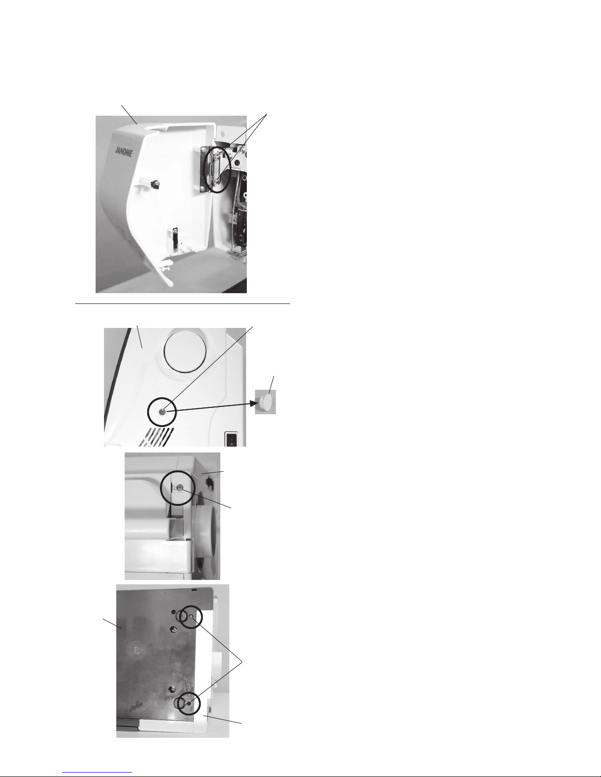
Face cover...........................................................................................................................................1
Belt cover ............................................................................................................................................1
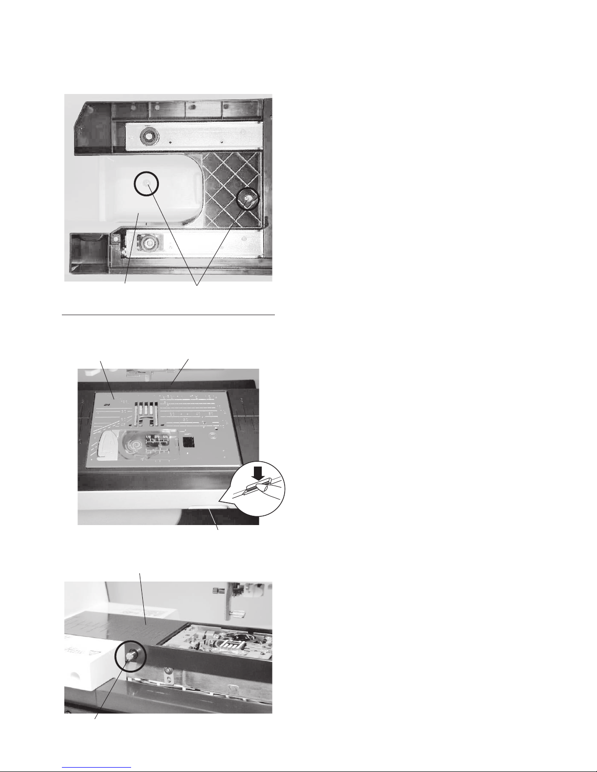
Top cover.............................................................................................................................................2
Base plate ...........................................................................................................................................3
Base cover ..........................................................................................................................................3
Bed cover ............................................................................................................................................4
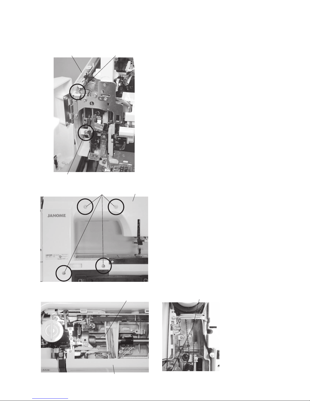
Free arm cover................................................................................................................................ 4-5
Front cover ..........................................................................................................................................6
Rear cover...........................................................................................................................................7
REPLACING ELECTRONIC COMPONENTS
Printed circuit board A.........................................................................................................................8
Printed circuit board F.........................................................................................................................9
Printed circuit board B (USB board)....................................................................................................9
Switching power supply unit..............................................................................................................10
Driving motor.....................................................................................................................................11
Thread tension unit ...........................................................................................................................12
MECHANICAL ADJUSTMENT
Feed dog height ................................................................................................................................13
Clearance between needle and tip of the rotary hook ................................................................ 14-15
Backlash between hook drive gear and lower shaft gear..................................................................16
Needle drop position .........................................................................................................................17
Hook timing .......................................................................................................................................18
Needle bar height..............................................................................................................................19
Upper shaft shield plate position.......................................................................................................20
Upper thread tension.........................................................................................................................21
Tension release mechanism..............................................................................................................22
Needle threader plate........................................................................................................................23
Thread drawing lever.........................................................................................................................24
Buttonhole lever adjustment..............................................................................................................25
Presser bar lifter switch position .......................................................................................................26
Embroidery foot height......................................................................................................................27
Embroidery foot detecting sensor adjustment...................................................................................28
Presser foot lifter switch adjustment..................................................................................................29
Knee lifter..........................................................................................................................................30
Thread cutter.....................................................................................................................................31
Remaining bobbin threader sensor...................................................................................................32
Needle plate sensor .................................................................................................................... 33-34
Bobbin winder ...................................................................................................................................35
Stretch stitch feed balance................................................................................................................36
Y-carriage play adjustment................................................................................................................37
Adjusting X and Y sensors (simple adjustment)................................................................................38
Cloth guide start position ..................................................................................................................39

1
Setscrews
Face cover
Changing External Parts (1)
Face cover
To remove:
1. Remove the setscrews (2 pcs.).
Remove the face cover.
To attach:
1. Follow the above procedure in reverse.
Belt cover
To remove:
1. Remove the cap and setscrew A.
2. Loosen the setscrews B and C.
Remove the belt cover.
To attach:
1. Follow the above procedure in reverse.
Setscrew A
Belt cover
Cap
Setscrew B
Belt cover
Setscrew C
Belt cover
Base plate

2
Flange plate
Mark A
Spring
Mark A
Spring
Fig. 2
Changing External Parts (2)
Top cover
To remove:
1. Raise the carrying handle and remove the setscrew A.
2. Open the top cover. Pull out the flange plate from the
bobbin winder spindle (see fig. 2).
3. Remove the setscrew B and C.
3. Open the face cover. Close the top cover.
Raise the carrying handle and remove the top cover.
To attach:
1. Follow the above procedure in reverse.
To attach the flange plate, align the spring and mark A
of the flange plate, and push the flange plate down
until it snaps to the machine (see fig 4).
Setscrew A
Carrying
handle
Top cover
Face cover
Bobbin winder
Fig. 1
Fig. 3
Fig. 4
Setscrew B Setscrew C

3
Setscrews
Changing External Parts (3)
Base plate
To remove:
1. Remove the setscrews (x 4).
2. Remove the base plate.
To attach:
1. Follow the above procedure in reverse.
Base plate
Fig. 1
Rail cover
Setscrews
SetscrewsBase cover
Fig. 2
Base cover
To remove:
1. Slide the rail cover in the direciton of arrow to remove
the rail cover (see fig 1).
2. Remove the setscrews (X4) (see fig 2).
Remove the base cover.
To attach:
1. Follow the above procedure in reverse.

4
Pin
Free arm cover
Changing External Parts (4)
Bed cover
To remove:
1. Remove the setscrews (x 2).
2. Remove the bed cover.
To attach:
1. Follow the above procedure in reverse.
Bed cover Setscrew
Fig. 1
Fig. 2
Needle plate Free arm cover
Free arm cover
To remove:
1. Remove the needle and presser foot holder.
2. Press down the needle plate release lever to release
the needle plate (see fig. 1).
3. Remove the bed cover.
Needle plate release lever
4. Remove the pin (see fig. 2).

5
Front right edge of the free arm cover Guide
Fig. 3
Setscrew
Free arm cover
Free arm cover
Free arm cover
Clearance
Changing External Parts (5)
Fig. 4
Fig. 5 Hook
Fig. 6
Fig. 7
6. Slide the free arm cover in the direction of arrow until
there is no clearance between the free arm cover and
the free arm (see fig. 4).
7. Lift up the free arm cover and slide it to the left while
removing the hooks from the machine.
Remove the free arm cover.
To attach:
1. Follow the above procedure in reverse.
Match the hooks and holes of the machine.
Press down the free arm cover firmly and slide it to
the right (see fig. 5).
Slide the free arm cover to the right while pulling the
front cover to the front when the front right edge of the
free arm cover touched to the projection (see fig. 6).
2. Tighten the setscrew and pin (see fig. 2 and 3).
3. Slide the guides of the needle plate to the machine,
and press it down until it snaps to the machine (see
fig. 7).
Projection
5. Loosen the setscrew (see fig. 3).

6
Front cover
To remove:
1. Remove the belt cover, top cover and base plate (see
pages 1, 2 and 3).
2. Loosen the setscrews A, B, C, D and E (see fig. 1-5).
3. Push the rear cover through the holes F and G with a
screwdriver to remove the hook of rear cover.
4. Remove the front cover.
To attach:
1. Follow the above procedure in reverse.
Changing External Parts (6)
Fig. 1
Fig. 2
Fig. 3 Fig. 4
Setscrew A
Front cover
Setscrew B Front cover
Hole F
Hole G
Setscrew D
Front coverSetscrew C
Fig. 5 Setscrew E Front cover

7
Changing External Parts (7)
Fig. 1 Rear cover Setscrew A
Setscrew B
Fig. 2 Setscrew C
Rear cover
To remove:
1. Lower the presser foot.
2. Remove the belt cover, top cover and base cover (see
pages 1, 2 and 3).
3. Loosen the setscrews A and B (see fig. 1).
Remove the setscrews C (see fig. 2)
4. Push the rear cover from the holes D and E with a
screwdriver to remove the hook of rear cover.
5. Remove the rear cover.
To attach:
1. Follow the above procedure in reverse.
Rear cover
Fig. 3 Hole D
Front cover
Fig. 4 Hole E

8
Replacing electronic components
Printed circuit board A
To remove:
1. Remove the front cover (see page 6).
2. Grasp the connector directly with your fingers and pull.
Do not pull the lead wire, as this may damage the
contact sleeve inside the connector.
Remove the setscrews.
Remove the printed circuit board A.
* Pull out the flexible cable behind the printed circuit
board A after removing the setscrews.
To attach:
1. Follow the above procedure in reverse.
Be sure that the connector post on the printed circuit
board to which it is connected.
Position the connector correctly, then push it straight
down until it locks in place.
Setscrew
Setscrew
Printed circuit
board A
DC motor (White)
Needle plate switch (White)
Drop feed switch (Brown)
Foot control / External
thread cutter jack
Power switch (White)
Printed circuit board A connection
Slide volume (White)
Printed circuit board L1 (White)
Printed circuit board L2 (Red)
(Face cover lamp)
Printed circuit board F (Black)
(Start/stop button)
Presser foot lifter switch (White)
Printed circuit board G1 (Black)
(Buttonhole sensor)
Printed circuit board G1 (Black)
(Embroidery foot detecting sensor)
Printed circuit board G1 (White)
(Thread cut detecting sensor)
Embroidery unit (White)
Thread cutter motor / Microswitch
(White)
Bobbin thread remaining sensor
(White)
Printed circuit board G2 (Black)
(Feed motor)
Bobbin winder switch (Blue)
Touch panel
Printed circuit board L2 (Black)
(Face cover lamp)
Printed circuit board P (Black)
(Upper shaft sensor )
Printed circuit board B (Black)
(USB board)
Printed circuit board G2 (White)
(Stitch width motor)
Printed circuit board G3 (Black)
(Thread tension motor)
Bobbin thread detecting
motor / microswitch (Green)
Not used

9
Replacing electronic components
Printed circuit board F
To remove:
1. Remove the front cover (see page 6).
2. Disconnect the connector from the circuit board A
(see page 8).
3. Remove the CS rings.
4. Remove the setscrews and the circuit board F.
To attach:
1. Follow the above procedure in reverse.
CS ring Printed circuit board F
Setscrew
Printed circuit board B (USB board)
To remove:
1. Remove the belt cover and base plate (see pages 1
and 3).
2. Loosen the setscrew. Remove the cord guide plate
(see fig. 1).
3. Pull out the connector of printed circuit board B from
printed circuit board A.
4. Remove the setscrews, and the printed circuit board B
with the case B. (see fig. 3)
5. Remove the hook from the printed circuit board B.
To attach:
1. Follow the above procedure in reverse.
Figure 1 Figure 2
Figure 3
Setscrew
Cord guide plate
Connector of
printed circuit board B
Printed circuit
board B
Case B
Setscrew
Hook

10
Switching power supply unit
To remove:
1. Remove the belt cover (see page 1).
2. Loosen the setscrew A. Remove the cord guide plate.
(see fig. 1)
3. Disconnect the relay connector between the printed
circuit board A and the switching power supply unit
(see fig. 2).
4. Disconnect the power supply connector from the
switching power supply unit (see fig. 3).
5. Remove the setscrews B, C and D (see fig. 3).
Remove the switching power supply.
To attach:
1. Follow the above procedure in reverse.
Replacing electronic components
Switching power supply unit
Fig. 1 Fig. 2
Relay connector
Setscrew A
Cord guide plate
Fig. 3 Power supply connector Switching power
supply unit
Setscrew B
Setscrew C
Setscrew D

11
Driving motor
To remove:
1. Remove the belt cover and the base plate (see pages
1 and 3).
2. Loosen the setscrew A and remove the cord guide
plate (see fig. 1).
3. Disconnect the DC motor connector from the printed
circuit board A (see page 8).
4. Remove the setscrews B, and the DC motor (see fig. 2).
Replacing electronic components
To attach:
1. Attach the driving motor. Tighten the setscrews
temporarily.
2. Adjust the motor belt deflection to about 5 mm by
pressing the middle of the motor belt with
approximately 200 grams of pressure.
3. Tighten the setscrews B securely.
4. Plug the driving motor connector to the printed circuit
board A.
5. Attach the base plate and the belt cover (see pages 1,
2 and 6).
Fig. 1
Fig. 2
Setscrew A
Cord guide plate
DC motor
connector
DC motor
Setscrew B Motor belt
200 g pressure
5 mm
Setscrew

12
Replacing electronic components
Thread tension unit
To remove:
1. Remove the belt cover, top cover, base plate and front
cover (see pages 1, 2, 3 and 6).
2. Disconnect the printed circuit board G3 (thread
tension motor) connector and printed circuit board G1
(thread cut detecting sensor) connector (see page 8).
3. Remove the sping on the thread tension release lever
(see fig. 1).
4. Remove the setscrews A and B (see fig. 2 and 3).
Remove the thread tension unit.
To attach:
1. Follow the above procedure in reverse.
Check the following parts after this adjustment.
• Check the upper thread tension (see page 21).
• Check the thread tension release mechanism (see
page 22).
• Check the presser foot lifter detecting switch (see
page 29).
• Check the knee lifter position (see page 30).
Thread tension unit
Thread tension
release lever
Fig. 1
Fig. 2
Fig. 3
Setscrew A
Setscrew B
Spring

13
⇒
Mechanical adjustment
Feed dog height
When the foot pressure dial is at “5” and the presser foot A is lowered, the highest position of the feed dog should be 0.80
to 0.90 mm from the surface of the needle plate.
Presser foot
Feed dog
0.85±0.05 mm
Surface of
needle plate
Reverse
stitch button
Start/stop
button
Setscrew A Nut Adjusting screw
Setscrew B Threaded hole
Hexagonal socket screw 4x6
Adjustment 1:
1. Attach the presser foot A. Remove the bed cover (see
page 4).
2. Turn the power switch on while pressing start/stop
button to enter the factory setting mode.
Press “Foot Sen/Feed Dog” key.
The stitch length will be set at “5.0”.
3. Set the pressure adjusting dial at “5” with the presser
foot lowered.
Turn the handwheel toward you to raise the feed dog
at its highest position.
4. Loosen the setscrew A.
5. Loosen the nut.
Adjust the feed dog height to 0.85 mm by turning the
adjusting screw.
6. Tighten the nut and setscrew A.
7. Attach the bed cover.
8. Check if the feed dog is parallel to the surface of the
needle plate at its highest position.
If not, make the adjustment as follows:
Adjustment 2:
If the feed dog is not parallel to the surface of the needle
plate at its highest position, make the adjustment as
follows:
* For this adjustment, a hexagonal socket screw 4x6, part
no. 000111108 is required.
1. Remove the bed cover
Insert a hexagonal socket screw I, part no. 000111108
into the threaded hole until it stops.
2. Turn the setscrew B clockwise to loosen it.
3. Turn the hexagonal socket screw 4x6 until the feed
dog is parallel with the surface of the needle plate.
4. Tighten the setscrew B.
5. Remove the hexagonal socket screw 4x6.
6. Check the feed dog height again.

14
⇒
Mechanical adjustment
Clearance between needle and tip of the rotary hook
The clearance between the needle and the point of hook should be -0.1 to +0.05 mm.
1. Remove the top cover (see page 2).
2. Remove the presser foot pressure dial, presser foot,
the needle plate and the bobbin holder. (see page 4
and 5)
* Cover the needle plate with the fabric to prevent
damaging the needle plate when removing.
3. Attach the master needle (see fig.1).
4. Turn the power switch ON while pressing start/stop
button and reverse stitch button to enter the factory
setting mode. Press "Bobbin" key.
The stitch width will be set at 9.0.
5. Turn the handwheel toward you. Adjust the clearance
between the needle and the tip of the rotary hook, by
moving the needle bar supporter in the direction
of arrow (see fig.3).
6. Check the clearances A and B between the needle
and the edge of needle plate hole (see fig. 4).
If the clearances are not even, follow the procedure in
the next page.
Adjustment 1
Master needle
Tip of hook
-0.1 to +0.05
mm
Left needle
position
Right needle
position
Needle plate hole
Setscrew
Needle bar
supporter
Center
Reverse
stitch button
Start/stop
button
Needle bar
Needle bar supporter
Presser foot pressure
adjusting dial
Clearances must be even
A
B
Fig. 1 Fig. 2
Fig. 3
Fig. 4

15
Adjustment 2
1. Remove the base cover and bed cover (see page 3
and 4).
2. Loosen the setscrews A and B.
Loosen the setscrew C just enough to move the hook
base plate (see fig. 5).
3. Turn the handwheel toward you.
Adjust the clearance between the needle and the tip
of the rotary hook by moving the hook base plate up
or down between -0.1and +0.05 mm at the both left
and right needle position (see page 14).
4. Tightent the setscrews A, B and C.
Check the following parts after this adjustment.
• Check the backlash between the lower shaft gear and
the hook drive gear. If the backlash is too great or the
engagement of the gears is too tight, adjust the
backlash (see page 16).
• Check the hook adjustment and needle bar height
after this adjustment (see page 18 and 19)
Setscrew C
Setscrew B
Setscrew A
Hook base plate
Fig. 5

16
Mechanical adjustment
Backlash between hook drive gear and lower shaft gear
The rotary play of the hook should be 0.8 mm or less when the tip of rotary hook is within the width of feed dog.
1. Remove the presser foot, the needle plate and the bobbin
holder. (see page 4 and 5)
* Cover the needle plate with the fabric to prevent
damaging the needle plate when removing.
2. Remove the base cover and bed cover (see page 3 and 4).
3. Turn the handwheel toward you so the the tip of the
rotary hook is within the width of feed dog as shown in
figure 1.
Check the rotary play of the hook.
4. If the backlash is too much or too little, loosen the
hexagonal socket screw (C) and (D) and following the
adjustment procedure.
If the backlash is too great (more than 0.8 mm), turn the
both lower shaft bushings in direction A. If the
engagement of gear is too tight, and the machine does
not turn smoothly, turn the both lower shaft bushings in
direction B.
Adjust the grooves of the lower shaft bushing as well.
5. Tighten the hexagonal socket screws.
• Check the hook adjustment and needle bar height
after this adjustment (see page 18 and 19)
Fig. 1
Tip of rotary hook
Width of feed dog
0.8 mm or less
Hexagonal
socket screw (C)
Lower bushing of the front side
Lower shaft bushing
Lower shaft gear
Lower shaft gear
Hook driving gear
A
B
Lower bushing of the belt cover
Lower shaft bushing
Hexagonal
socket
screw (D)

17
⇒
Mechanical adjustment
Needle drop position
When the straight stitch is selected, the needle should be positioned in the center of the needle plate hole.
When the needle drop position is set at "0.0" and "9.0", the clearance between the side of the needle and the needle
hole should be 0.2 mm or more.
To adjust:
1. Attach the needle #14.
2. Turn the power switch ON while pressing start/stop
button and reverse stitch button to enter the factory
setting mode.
Press "Bobbin" key.
The stitch width will be set at 9.0.
3. Turn the handwheel toward you.
Check that the needle drop position is centered
when the drop position is set at "4.5", and the
clearance between the side of the needle and the
needle hole is 0.2 mm or more when the needle
position is set at "0.0" and "9.0" (see fig. 1).
If this is not the case, adjust as follows;
3. Lower the needle threader until the hexagonal socket
screw shows up (see fig. 2).
Loosen the hexagonal socket screw. Turn the
eccentric pin to adjust the needle drop position.
The direction of eccentric pin should be as shown as
fig. 3.
4. Tighten the hexagonal socket screw.
Check the hook timing and the needle bar height after
this adjustment (see page 15 and 16).
Needle hole
0.2 mm or more0.2 mm or more
A = B
“9.0”
Needle drop position "4.5"
“0.0”
Reverse
stitch button
Start/stop
button
Hexagonal
socket screw
Hole
Needle threader
lever
Eccentric pin
Pin
Eccentricity
Fig. 1
Fig. 2
Fig. 3

18
⇒
Mechanical adjustment
Hook timing
The amount of ascending travel of the needle bar from its lowest position to the position (Needle drop position 0.0)
where the tip of the rotary hook exactly meets the right side of the needle should be 3.70 to 4.00 mm
To adjust:
1. Attach the needle #14.
2. Turn the power switch ON. Select straight stitch .
Set the needle drop position at "0.0".
Turn the power switch OFF.
3. Remove the presser foot, the needle plate and the
bobbin holder. (see page 4 to 5)
* Cover the needle plate with the fabric to prevent
damaging the needle plate when removing.
4. Remove the bed cover (see page 4).
5. Turn the handwheel toward you to lower the needle at
its lowest position.
6. Loosen the setscrews of the lower shaft gear.
7. Turn the handwheel toward you to raise the needle bar
further 3.85 mm from its lowest position.
8. Turn the lower shaft gear until the tip of ratary hook
meets with the right side of the needle.
Tighten the setscrews of the lower shaft gear.
• Check the needle bar height after this adjustment (see
page 19).
3.70 to 4.00 mm
Lowest needle
position
Needle #14
Hook
Tip of hook meets the
right side of the needle
(Needle drop position 0.0)
Adjust key Adjusting window
Bobbin holder Hook Tip of hook
Lower shaft gear Setscrew
Other manuals for MC9900
1
Table of contents
Other Janome Sewing Machine manuals

Janome
Janome MC 200E - User manual

Janome
Janome 625E User manual

Janome
Janome 1110DX PRO User manual

Janome
Janome Sewing Machine User manual

Janome
Janome S750 Troubleshooting guide

Janome
Janome MC230E User manual

Janome
Janome OC 6125 User manual

Janome
Janome 4030QDC User manual

Janome
Janome 5060DC User manual

Janome
Janome 234 User manual

Janome
Janome MyLock 213 User manual

Janome
Janome 3160QDC - User manual

Janome
Janome MC6600P User manual

Janome
Janome 792PG User manual

Janome
Janome Sewing Machine User manual

Janome
Janome Magnolia 7318 User manual

Janome
Janome Memory Craft 500E User manual

Janome
Janome M50QDC User manual

Janome
Janome MS3015 User manual

Janome
Janome 15 User manual