Janome 5270QDC Troubleshooting guide

First Edition: 06 March 2020
SERVICE MANUAL
&
PARTS LIST
MODEL: 5270QDC
(For Europe only)

INDEX
What to do when.............................................................................................................................. 1 to 3
CHANGING EXTERNAL PARTS
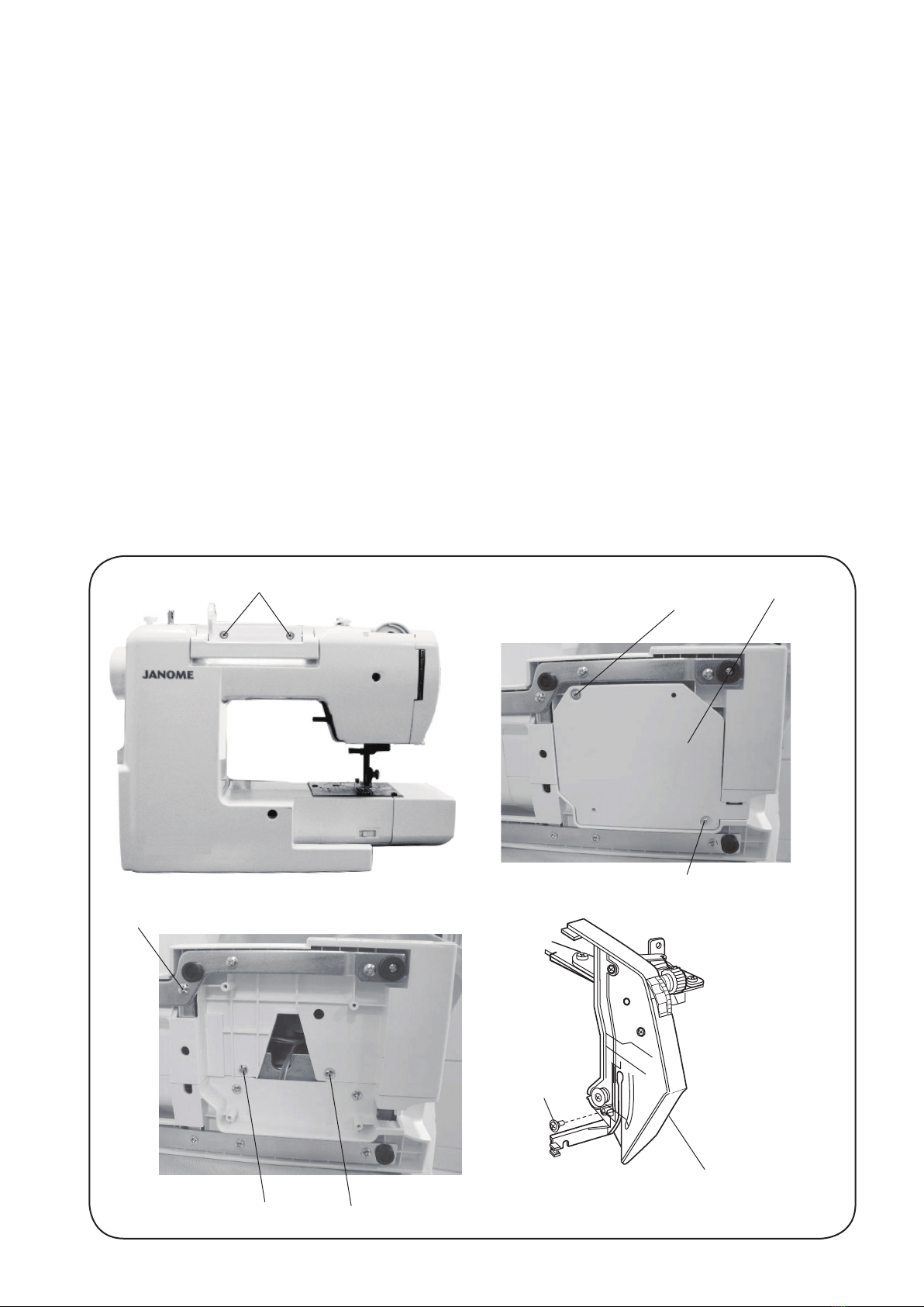
FACE COVER .........................................................................................................................................4
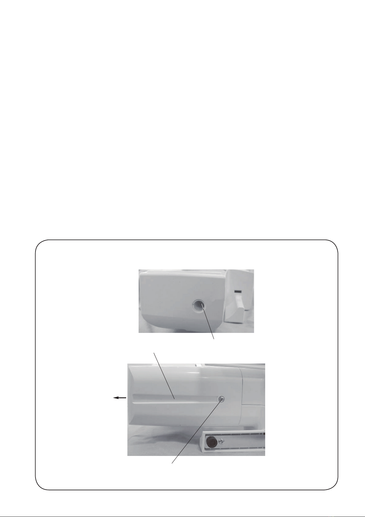
FREE ARM COVER ...............................................................................................................................5
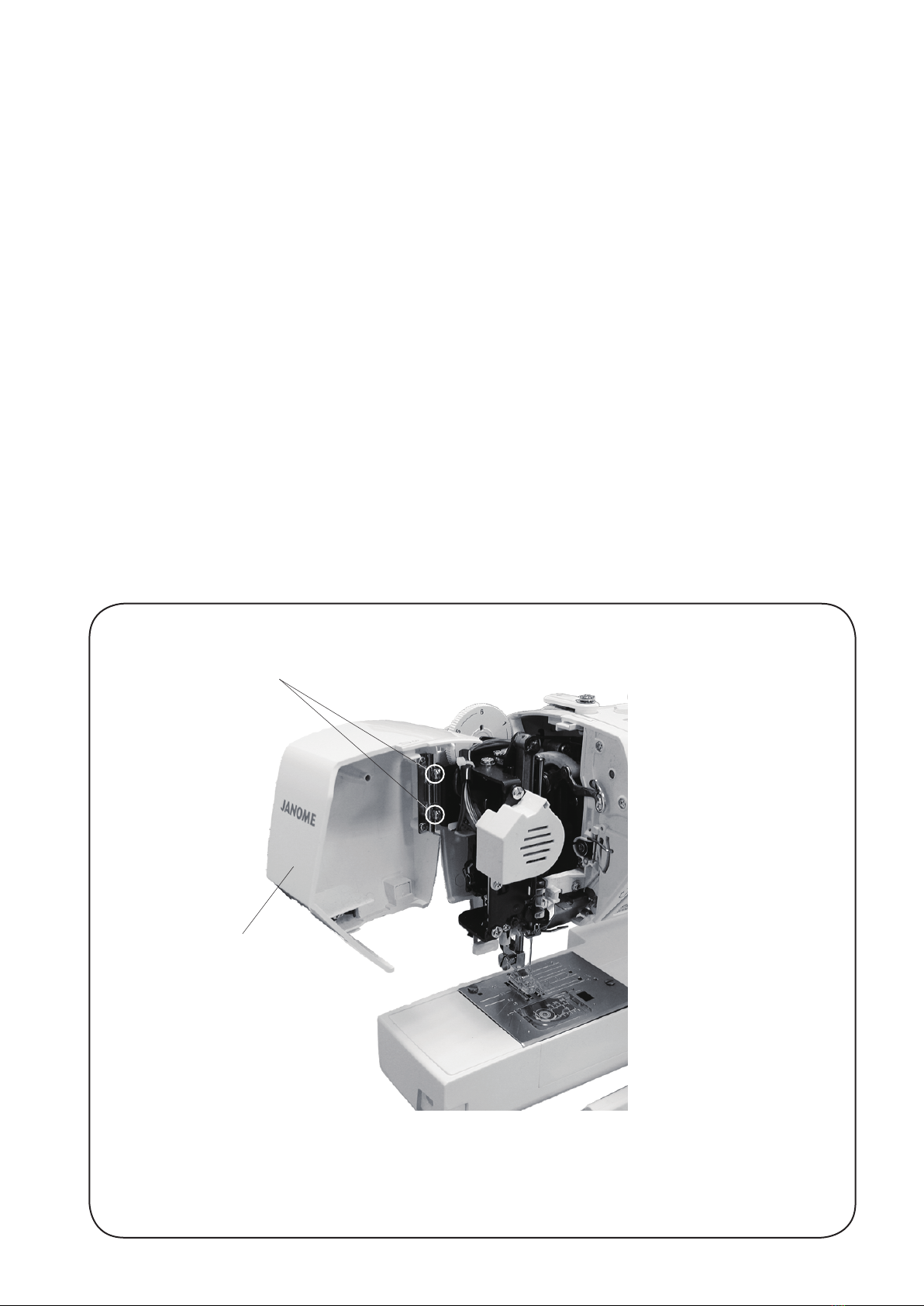
FRONT COVER ...............................................................................................................................6 to 7
REAR COVER.........................................................................................................................................8
MECHANICAL ADJUSTMENT
PRESSER BAR HEIGHT ........................................................................................................................9
NEEDLE DROP POSITION...................................................................................................................10
ADJUSTMENT OF HOOK TIMING .......................................................................................................11
ADJUSTMENT OF NEEDLE BAR HEIGHT..........................................................................................12
CLEARANCE BETWEEN NEEDLE AND TIP OF THE ROTARY HOOK ..............................................13
FEED DOG HEIGHT .............................................................................................................................14
FEED DOG ADJUSTMENT...................................................................................................................15
TOP TENSION ......................................................................................................................................16
STRETCH STITCH FEED BALANCE ...................................................................................................17
ADJUSTING BUTTONHOLE LEVER POSITION..................................................................................18
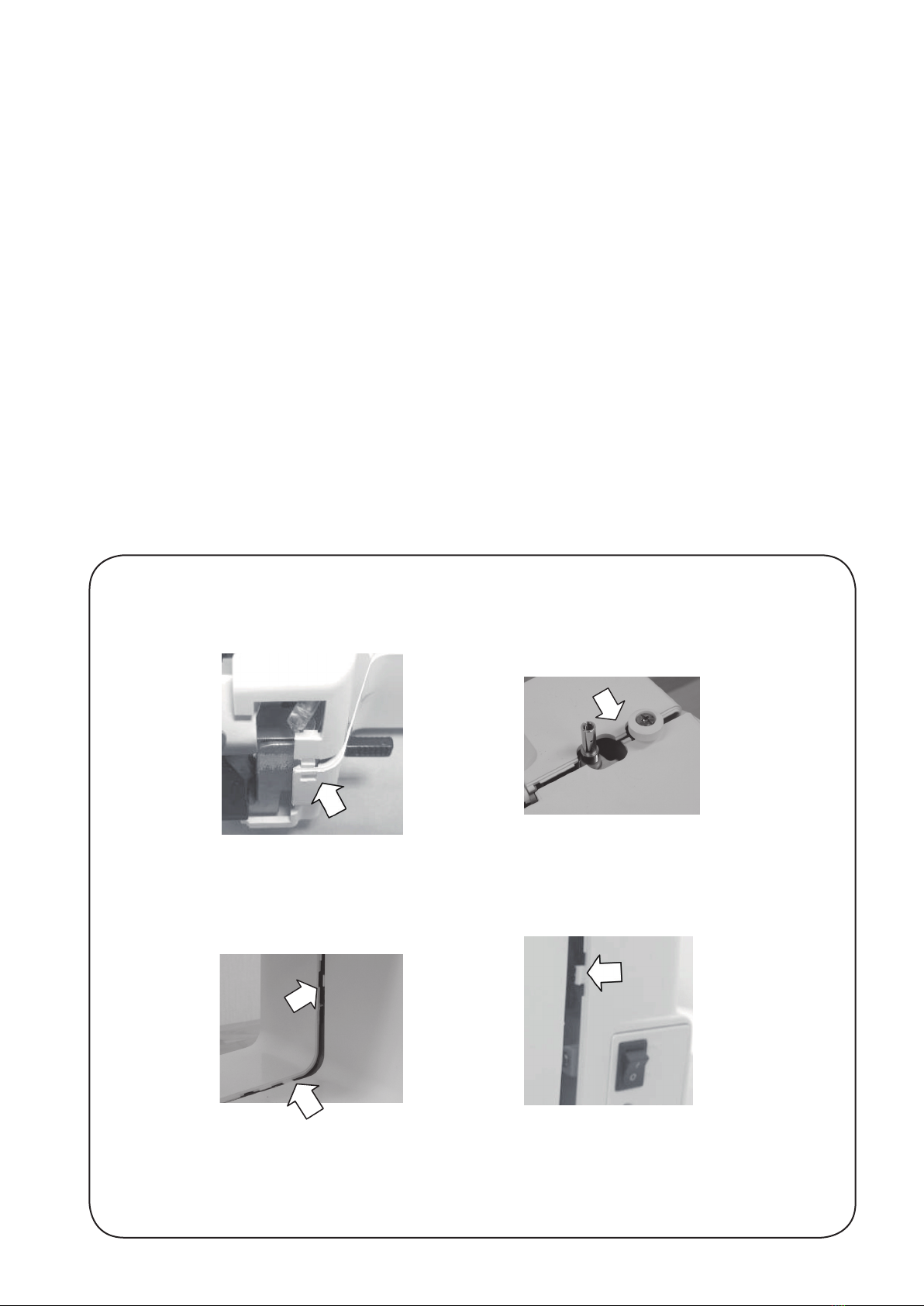
REPLACING AND ADJUSTING THE PRESSER FOOT LIFTER SWITCH UNIT.................................19
REPLACING AND ADJUSTING THE KNEE LIFTER WIRE UNIT...............................................20 to 21
REPLACING AND ADJUSTING THE NEEDLE THREADER HOLDER.......................................22 to 23
THREAD CUTTER ................................................................................................................................24
SELF-DIAGNOSTIC TEST
SELF-DIAGNOSTIC TEST...........................................................................................................25 to 30
TO DISPLAY THE VERSION OF THE PROGRAM...............................................................................30
REPLACING THE ELECTRONIC COMPONENTS
PRINTED CIRCUIT BOARD A CONNECTION .....................................................................................31
PRINTED CIRCUIT BOARD A ..............................................................................................................32
DRIVING MOTOR .................................................................................................................................33
SWITCHING REGULATOR UNIT..........................................................................................................34
CLEANING AREA OF THREAD CUTTER AND LOWER SHAFT GEAR..............................................35
KEY POSITION ADJUSTMENT ............................................................................................................36
TOUCH PANEL KEY POSITION ADJUSTMENT GUIDE PRINTED
THE ILLUSTRATION (ACTUAL SIZE) .............................................................................................37
PARTS LIST.................................................................................................................................38 to 53

1
Condition Cause How to fix Reference
1. Skipping
Stitches
1. Needle is not inserted properly.
2. Needle is bent or worn.
3. Incorrectly threaded.
4. Needle or thread are
inappropriate for the fabric
being sewn.
5. Sewing on stretch fabric.
6. Inappropriate needle bar height.
7. Inappropriate needle to hook
timing.
8. Inappropriate needle to hook
clearance.
Insert the needle properly.
Change the needle.
Rethread.
Use the recommended sewing needle
and thread.
Use a HA x #11 blue tip needle.
See mechanical adjustment “Adjustment
of needle bar height”.
See mechanical adjustment “Adjustment
of hook timing”.
See mechanical adjustment “Clearance
between needle and tip of the rotary
hook”.
P. 1 2
P. 1 1
P. 1 3
2. Fabric not
moving
1. Incorrect feed dog height.
2. Feed dog is in down position.
3. Thread on bottom side of
fabric is jammed up.
See mechanical adjustment “Feed dog
height”.
Raise the feed dog.
Make sure to bring both needle and
bobbin threads under the foot when start
sewing.
P. 1 4
WHAT TO DO WHEN

2
Condition Cause How to Fix Reference
3. Breaking
upper
thread.
1. Initial sewing speed is
too fast.
2. Thread path is incorrect.
3. Needle is bent or dull.
4. Top tension is too strong.
5. Needle size is inappropriate for
fabric.
6. Needle eye is worn.
7. Needle hole in needle plate is
worn or burred.
Start with medium speed.
Use the proper thread path.
Replace with a new needle.
Adjust top tension correctly.
Use appropriate needle for fabric and
thread in use.
Change the needle.
Repair the hole or replace the needle
plate.
4. Breaking
bobbin
thread.
1. Bobbin holder is incorrectly
threaded.
2. Too much thread is wound
on the bobbin.
3. Lint is stuck inside the bobbin
holder.
4. Thread quality is too low.
5. Thread is jamming around the
bobbin holder.
Set the bobbin thread correctly.
Adjust the position of bobbin winder
stopper.
Clean the bobbin holder.
Change to a high quality sewing thread.
Clear out the jamming thread.
5. Needle
breaks
1. Needle is hitting the needle plate.
2. Needle is bent or worn.
3. Needle is hitting the hook.
4. Fabric is being pulled too strongly
while sewing.
See mechanical adjustment “Needle drop
position”.
Change the needle.
See mechanical adjustment “Clearance
between needle and tip of the rotary
hook”.
Guide the fabric gently while sewing.
P. 1 0
P. 1 3
P. 1 6
WHAT TO DO WHEN

3
Condition Cause How to fix Reference
6. Noisy
operation
1. Backlash between hook gear
and lower shaft gear is too
great.
2. Lower shaft gear is loose.
3. Inappropriate belt tension.
4. Not enough oil.
5. Upper shaft gear is loose.
Eliminate the backlash.
Eliminate the looseness.
See part removal and replacement
“Driving motor (DC motor)”.
Oil all moving parts.
Eliminate the looseness.
P. 3 3
7. Deformation
pattern
1. Inappropriate feed balance.
2. Top tension is too strong.
Adjust the feed balancing dial.
See mechanical adjustment
“Top tension”.
P. 1 7
P. 1 6
WHAT TO DO WHEN

4
CHANGING EXTERNAL PARTS
FACE COVER
To remove:
1. Remove the setscrews (2 pcs.) qand remove the face cover w.
To attach:
2. Follow the above procedures in reverse.
q
w

5
FREE ARM COVER
To remove:
1. Remove the setscrews q(2 pcs.). Move the free arm cover wto the left.
Remove the free arm cover.
To attach:
2. Follow the above procedures in reverse.
CHANGING EXTERNAL PARTS
q
q
w

6
CHANGING EXTERNAL PARTS
FRONT COVER (1)
To remove:
1. Remove the face cover and free arm cover (see pages 4 and 5).
2. Remove the setscrews A q(2 pcs.).
3. Remove the setscrews B w(2 pcs.) and bed cover e.
4. Remove the setscrew C r.
5. Remove the setscrews D t(2 pcs.).
6. Loosen the setscrew E y.
qe
y
Thread tension unit
w
r
w
tt

7
CHANGING EXTERNAL PARTS
FRONT COVER (2)
7. Disengage the front cover and rear cover hooks.
8. Disconnect all the connectors from the circuit board A.
NOTE:
Do not disconnect the connectors by pulling on cord.
To disconnect, grasp the connector, not the cord.
9. Remove the front cover.
To attach:
10. Follow the above procedures in reverse.

8
CHANGING EXTERNAL PARTS
REAR COVER
To remove:
1. Remove the face cover and free arm cover (see pages 4 and 5).
2. Remove the setscrews A q(2 pcs.).
3. Remove the setscrews B w(3 pcs.).
4. Remove the setscrews C e(2 pcs.) and bed cover r.
5. Remove the setscrews D t(2 pcs.).
6. Remove the setscrew E y. Remove the rear cover.
To attach:
7. Follow the above procedures in reverse.
t
qwq
w
w
Rear cover
er
e
y

9
6.0 mm
MECHANICAL ADJUSTMENT
PRESSER BAR HEIGHT
The distance between the bottom of the presser foot in up position and the needle plate should be 6.0 mm.
1. Remove the face cover and needle.
2. Lower the feed dog below the needle plate.
Place a block 6 mm thick under the presser foot and lower the presser foot lifter w.
3. Loosen the setscrew q. Raise the presser foot lifter and tighten the setscrew qfirmly.
Attach the needle and face plate.
NOTE:
Make sure that the presser foot should be parallel to the feed dog slots ein the needle plate.
q
e
Presser foot should be parallel
to the feed dog slots.
w

10
0.2 mm
or more
0.2 mm
or more
A = B
MECHANICAL ADJUSTMENT
NEEDLE DROP POSITION
Set the stitch pattern to “ ”. The standard needle drop position should be at center of the needle plate hole q.
Select zigzag stitch “ ”, and set the stitch width at “7.0”. The clearance between the needle and the edge of the
needle plate hole should be at least 0.2 mm on either side. If not, adjust as follows:
1. Turn the power switch off. Remove the face cover (see page 4).
2. Loosen the hexagonal socket screw 3x4 w. Adjust the needle drop position by turning the eccentric pin.
The direction of eccentric pin should be as shown in FIG. 1.
3. Attach the face cover.
NOTE:
Check the hook timing after this adjustment.
q
w
FIG. 1
Rotation center
Eccentric Between the range of
downward direction

11
The amount of ascending travel of the needle bar from its lowest position to the position ( ) where the tip of
the rotary hook exactly meets the right side of the needle should be 3.25 to 3.55 mm.
1. Remove the setscrews (2 pcs.) on the needle plate, the needle plate and the bobbin holder.
2. Remove the free arm cover (see page 5).
3. Turn the power switch on.
4. Select the pattern (left position). Set the zigzag width at 0.
Turn the handwheel toward you to lower the needle at its lowest position.
5. Loosen the hexagonal socket screw (2 pcs.).
6. Move the needle bar 3.25 to 3.55 mm from the lowest position.
7. Turn the lower shaft gear until the tip of hook meets the right side of the needle while holding the handwheel.
8. Tighten the hexagonal socket screw (2 pcs.).
9. Attach the free arm cover, bobbin holder and needle plate.
MECHANICAL ADJUSTMENT
ADJUSTMENT OF HOOK TIMING
Hexagonal socket screw
Bobbin holder
Lower shaft gear
Left position ( ) (#14)
Tip of hook meets the right side of the needle
Lowest needle position
3.25 to 3.55 mm
Needle plate
Setscrew
Setscrew

12
Before proceeding with this adjustment, check the hook timing (see page 11).
The distance between the upper edge of the needle eye and the tip of the hook should be in the range of 1.6 to 2.0
mm when the tip of the hook timing meets right side of the needle in the left needle position ( ) as the needle
ascends from its lowest position.
1. Remove the setscrews (2 pcs.) on the needle plate, the needle plate and the bobbin holder.
2. Turn the power switch on.
3. Select the pattern (left position). Set the zigzag width at 0.
4. Turn the handwheel toward you until the tip of hook meets the right side of the needle.
5. Open the face cover.
6. Loosen the hexagonal socket screw.
7. Move the needle bar to adjust the needle bar height, and tighten the hexagonal socket screw.
Be careful not to turn the needle bar.
8. Attach the bobbin holder, needle plate and face cover.
MECHANICAL ADJUSTMENT
ADJUSTMENT OF NEEDLE BAR HEIGHT
Hexagonal socket screw
Needle setting
groove
Hook race (unit)
1.6 to 2.0 mm
Upper edge of the needle hole
Upper surface of hook race
Tip of hook meets the right side of the needle
Left position ( ) (#14)
Bobbin holder
Needle plate
Setscrew
Setscrew

13
Adjustment procedure:
1. Remove the setscrews A (2 pcs.) on the needle plate, the needle plate and the bobbin holder.
2. Attach the master needle. Turn the power switch on and set the zigzag width at maximum.
3. Open the face cover.
4. Loosen the setscrews B (2 pcs.).
5. Turn the handwheel toward you. Adjust the clearance between the needle and the tip of the rotary hook, by
moving the needle bar supporter adjusting plate up or down, to within –0.10 to +0.05 mm at the left and right
needle position.
6. Tighten the setscrews B (2 pcs.).
7. Attach the face cover. Remove the master needle. Attach the bobbin holder and needle pate.
8. Check the clearance between the needle and the edge of the needle plate hole (see page 10).
* The clearance between the needle and the point of hook should be –0.10 to +0.05 mm.
CLEARANCE BETWEEN NEEDLE AND TIP OF THE ROTARY HOOK
MECHANICAL ADJUSTMENT
–0.10 to +0.05 mm
Needle bar supporter
adjusting plate
Tip of the rotary hook
Bobbin holder
Needle plate
Setscrew A
Setscrew A
Setscrew B

14
The highest position of the feed dog should be between 0.80 to 0.90 mm from the surface of the needle plate.
1. Lower the presser foot and turn the power switch on.
2. Turn the handwheel toward you to set the feed dog at the highest position.
3. Remove the free arm cover.
4. Loosen the setscrew qand nut w.
5. Adjust the feed dog height by turning the adjusting screw e. The highest position of the feed dog should be
between 0.80 to 0.90 from the surface of the needle plate.
6. Tighten the nut w and setscrew q.
7. Attach the free arm cover.
FEED DOG HEIGHT
MECHANICAL ADJUSTMENT
A B
e
w
q
q
Presser foot
Feed dog
0.80 to 0.90 mm
Surface of the needle plate

15
MECHANICAL ADJUSTMENT
w
q
e
The highest position of the feed dog should be parallel to the surface of the needle plate.
If not, adjust as follows.
1. Use a hexagonal socket screw (4x6) q.
Insert the hexagonal socket screw (4x6) to the hole w.
Tighten the hexagonal socket screw (4x6) as far as it goes.
2. Loosen the setscrew e(left screw).
3. Turn hexagonal socket screw (4x6) to adjust the feed dog (should be parallel to the surface of the needle
plate).
4. Tighten the setscrew e (left screw).
5. Loosen the hexagonal socket screw (4x6) and remove it.
FEED DOG ADJUSTMENT

16
MECHANICAL ADJUSTMENT
TOP TENSION
The top tension should be between 65 to 80 grams-force when pulling the thread up in the direction of arrow.
* Use polyester sewing thread #50 (White).
* If it is not within the above limit, adjust as follows.
1. Set the tension dial “4”.
2. Remove the front cover (see pages 6 to 7).
3. Lower the presser foot.
• If the top tension is too loose, turn the lead screw in the direction (A).
• If the top tension is too tight, turn the lead screw in the direction (B).
4. Check the top tension and attach the cover.
White polyester thread size 50
Pull the thread at the speed of 110 mm/sec in the direction of arrow

17
MECHANICAL ADJUSTMENT
STRETCH STITCH FEED BALANCE
To check:
1. Enter the self-diagnostic mode (see below).
Attach the Satin stitch foot F. Place a fabric under the presser foot. Lower the presser foot.
2. Press the locking stitch button to start test sew, and check the results (the standard figure length of 5
pieces of figure 8 is 33 to 39 mm).
3. If stretch patterns are distorted, correct them with the feed balancing dial.
If stretch patterns are too deformed and cannot be corrected with the feed balancing dial, adjust as follows.
To adjust:
4. Remove the feed balancing dial cover. Turn the dial at standard position as illustrated.
Turn the power switch ON.
Select the straight stitch and set the stitch length at “0”. Place a fabric under the presser foot.
Lower the presser foot. (Do not set bobbin and needle threads)
5. Turn the hexagonal socket screw to the left to loosen it.
Move the gear up (A) or down (B) to adjust the feed.
* Do not move the gear right or left when adjusting.
Start the machine and check the movement of the fabric.
Adjust the hexagonal socket screw position (gear position) until the fabric will not be fed with the stitch
length setting at “0”.
6. Tighten the socket screw and attach the feed balancing dial cover.
Enter the self-diagnostic mode and test sew again. Check that the standard length of 5 pieces of figure 8 is
33 to 39 mm. If not, turn the feed balancing dial to correct it.
Correct IncorrectIncorrect
Feed balancing dial
(Standard position)
Hexagonal socket screw
Feed balancing dial cover
(A)
(B)
TO ENTER SELF-DIAGNOSTIC MODE:
Turn the power switch on while
simultaneously pressing needle
up/down button and thread
cutter button.
33 to
39 mm
Press the needle up/down button within the 1.5 seconds to enter
the self-diagnostic mode.
The LCD will indicate "----". Press “8” to enter the stretch stitch
test mode.
Gear
The standard figure length of 5 pieces of figure
8 is 33 to 39 mm.

18
BH sensor
BH symbol
1.6 mm gap
MECHANICAL ADJUSTMENT
ADJUSTING BUTTONHOLE LEVER POSITION
TO ADJUST THE BUTTONHOLE LEVER GUIDE:
1. Enter the self-diagnostic test of buttonhole sensor mode (see pages 25 and 26. The LCD should display 03
and BH symbol.)
2. Remove the face cover (see page 4) and loosen the setscrew q.
3. Move the buttonhole lever guide wso the BH symbol disappear when the buttonhole lever eis lowered.
Tighten the setscrew.
TO ADJUST THE BUTTONHOLE SENSOR POSITION:
4. Attach the buttonhole foot (R) r.
5. Lower the buttonhole lever eto its lowest position and open a 1.6 mm gap between the slider and the
buttonhole foot.
6. Turn the adjusting screw tto the left until the LCD display BH symbol.
7. Next, turn the adjusting screw to the right until the BH symbol disappears.
8. Turn off the power switch.
9. Attach the face cover.
q
w
r
e
t
NOTE: If there is any lint or dust in the buttonhole sensor slit, loosen the setscrews (2 pcs.) yand clean it out
with a swab.
y
y
TO ENTER BH REVER ADJUSTING MODE:
Turn the power switch
on while simultaneously
pressing needle up/down
button and thread cutter
button.
Press the needle up/
down button within the 1.5
seconds to enter the self-
diagonostic mode.
The LCD will indicate “----”.
Press the 1 key.
Press the start/stop button two times to enter
the BH lever adjusting mode.
Other manuals for 5270QDC
1
Table of contents
Other Janome Sewing Machine manuals

Janome
Janome 659 User manual

Janome
Janome XL601 User manual

Janome
Janome E1019 Troubleshooting guide

Janome
Janome AQS2009 User manual

Janome
Janome QMP16SU User manual

Janome
Janome Sewing Machine User manual

Janome
Janome Continental M17 User manual

Janome
Janome AQS2009 User manual

Janome
Janome DC6100 User manual

Janome
Janome MC5200 - User manual

Janome
Janome 4119 User manual

Janome
Janome Memory craft 9900 User manual

Janome
Janome 990D User manual

Janome
Janome MC 200E - User manual

Janome
Janome S-7330 User manual

Janome
Janome MS5027 Pink Ribbon User manual

Janome
Janome MB-4 User manual

Janome
Janome 1110DX - User manual

Janome
Janome JD 1818 User manual

Janome
Janome C30 User manual