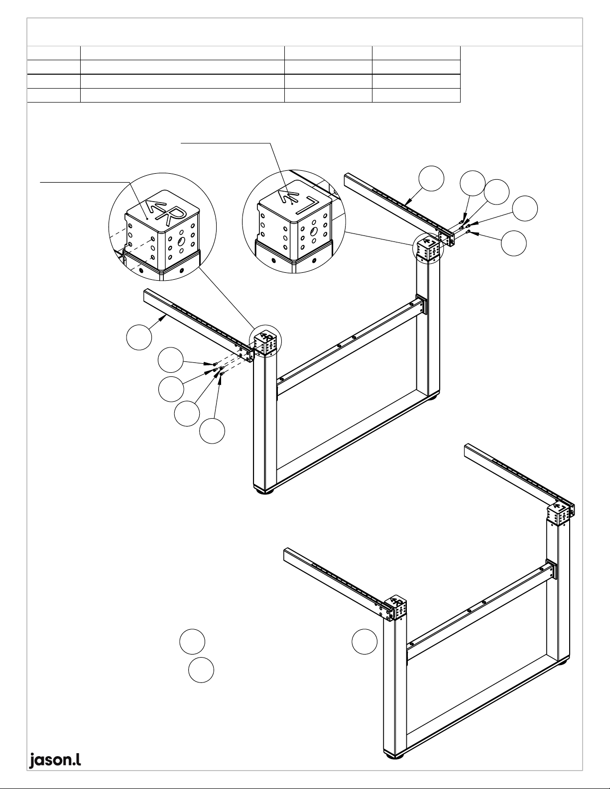
Notes:
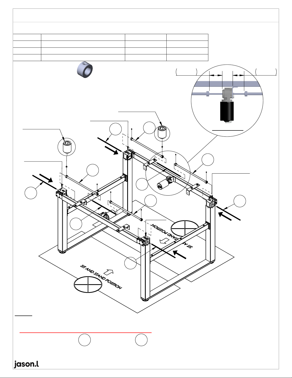
1.Before Insert Hex Shaft, make sure
Left Stand & Right Stand are at lowest position.
Please see attachment caution ! (Refer Pg.8/14)
2. After insert Hex Shaft
12
and Axle Drive
09 ,
align according as per Figure No.1 dimension.
3. Locking Set Screw M6(x4)
11
09
11
PRESS DOWN
PRESS DOWN
PRESS DOWN
PRESS
DOWN
11
11
12
09
12
09
09
Set Screw M6
(X4)
Set Screw M6
(X4)
CF
50~60 50~60
Figure No.1
V1.0 Pg.5/14
For Length 115cm
Remarks; Lock Bush
Item No. 09 (Axle Drive L400mm)
Lock Bush (X4) dismantle from
Item No. 10 (Axle Drive L550mm )
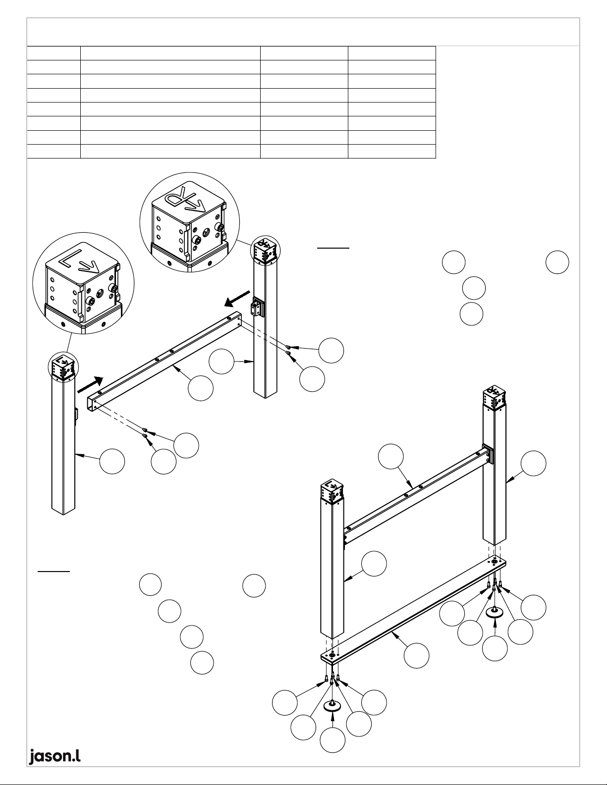
ITEM NO.
DESCRIPTION
QTY.BOX NO.1
QTY.BOX NO.2
09
Axle Drive L400mm
2 2
11
Hex Shaft L100mm
2 2
12
Hex Shaft L250mm
1 1
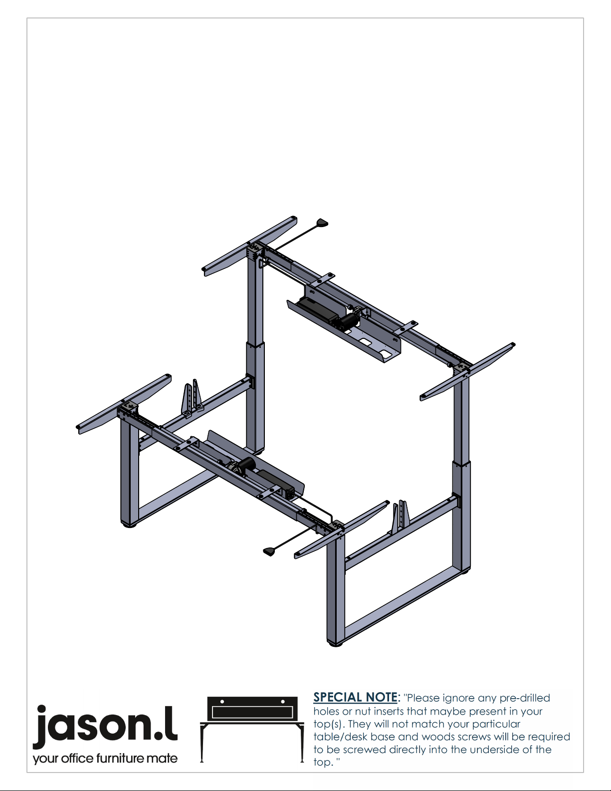
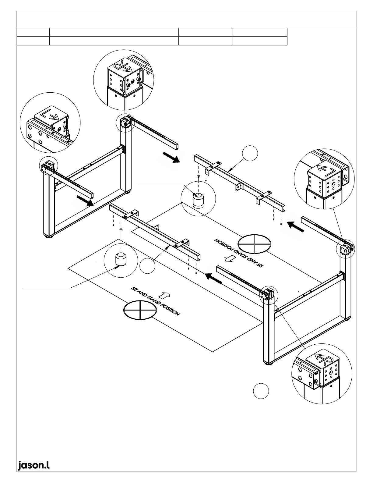
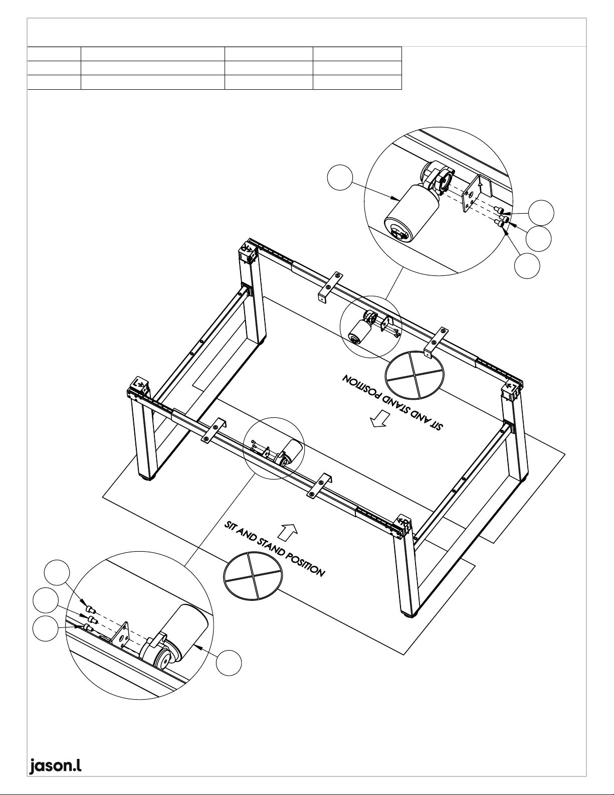
Assembly Instruction: Install Axle Drive And Hex Shaft