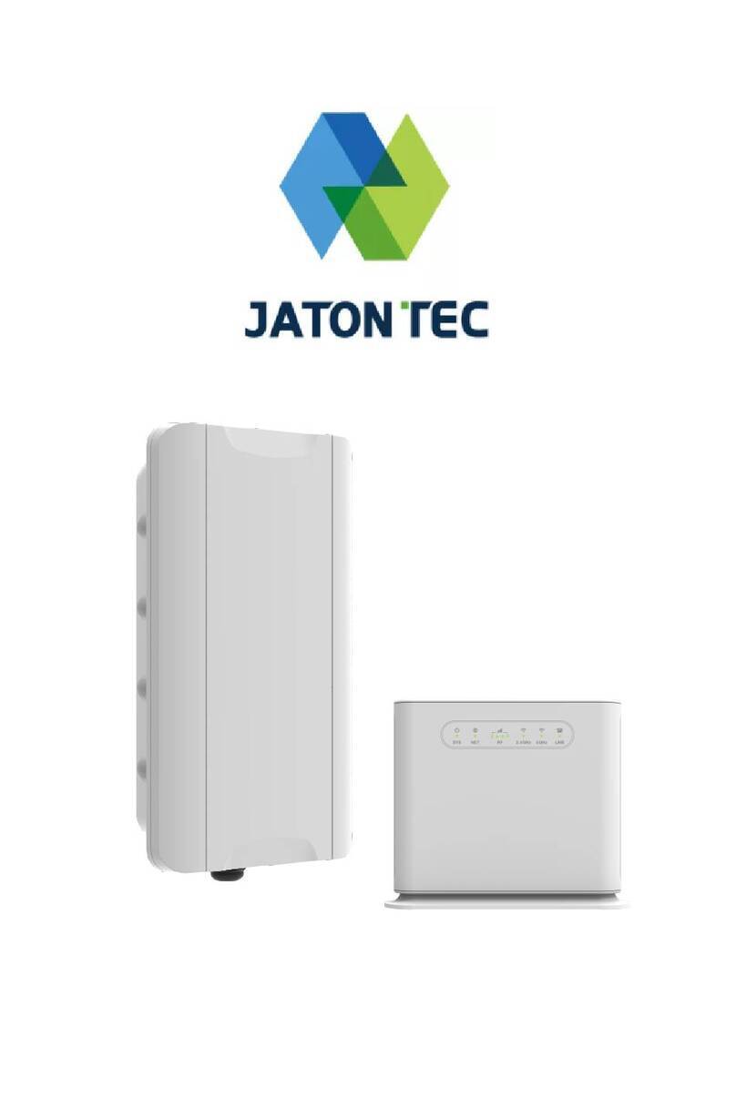
Jatontec JT8800M Instruction manual

5G NR ODU Combo CPE
Quick User Guide
JT8800M

2
Device Package
Products
Quantity
ODU Unit
1
IDU Unit
1
48V DC Power Adapter
1
Ethernet Cable
1
Clamps
2
Quick User Guide
1
Device External Interface

3
Environmental Specification
Feature
Specs.
Operating temperature
ODU: -40 to 55℃, IDU: -15 to 50℃
Storage temperature
-45 to 85℃
Operating humidity
0 to 95% No condensation

4
Getting Your Device Ready for Connection
Insert the SIM CARD (ODU)
Before powering on the device, please insert the SIM card in the direction indicated
on the bottom of the device.
Installing Outdoor Unit
Use the clamps provided in the packaging to secure the equipment onto the pole.
Step 1
Step 2

5
Use the mounting brackets provided in the packaging to secure the equipment onto
the pole.
Header Connection
Grounding
Make sure that the installation of the outdoor unit, antenna and cables is performed
in accordance with all relevant national and local building and safety codes. Even
where grounding is not mandatory according to applicable regulation and national
codes, it is highly recommended to ensure that the outdoor unit and the antenna
mast are grounded and suitable lightning protection devices are used so as to
provide protection against voltage surges and static charges. In any event, we not
liable for any injury, damage or regulation violations associated with or caused by
installation, grounding or lightning protection.
Step 3

6
The Grounding screw is located on the lower part at the back of the unit (see Figure
below). Use 10 AWG cable for grounding.
Connect one of a grounding-wire to the grounding screw and firmly tighten the
grounding screw. Connect the opposite end of the grounding cable to a good
ground(earth) connection.
Power on
Before connecting the device to AC power, please refer to the diagram and connect
the PoE port of the ODU to the PoE port of the IDU using an Ethernet cable. Once
the connection is confirmed to be reliable, connect the power adapter provided with
the device to the power input port of the IDU and then turn on the power switch of
the IDU device. The SYS light of the IDU device will illuminate.
Step 4

7
LED Display
(ODU)
LED
Function
Descriptions
SYS
System Indicator
Light is on - Device is power on.
MOD
WAN Port Status
OFF - NO wireless network access.
Light is on - WAN data transmission in progress.
SIM
SIM Card Indicator
Light is on - SIM card state is ready.
Blinking - SIM card is error.
ETH
LAN Port Status
Light is on - LAN port is up.
Wi-Fi
Wi-Fi Status
This device does not support.
RF
(5LEDs)
RF Signal Strength
RF1 Blinking - Device searching for mobile network
entry.
1st LED: -115dBm < RSRP
2nd LED: -115dBm <= RSRP < -105dBm
3rd LED: -105dBm <= RSRP < -95dBm
4th LED: -95dBm <= RSRP < -85dBm
5th LED: -85dBm <= RSRP

8
(IDU)
LED
Function
Descriptions
SYS
System Indicator
Solid Orange - Device powering up and booting.
Solid Green - Normal operation.
Blinking Orange - SIM card absent or malfunction
detected.
NET
Mobile Network
Indicator
OFF - Not yet connected to mobile network.
Solid Green - Connected to 3G/4G network.
Solid Blue - Connected to 5G network.
RF
RF Signal Strength
RF1 Blinking Green - Device searching for mobile
network entry.
RF1 Solid Green: -123dBm <= RSRP < -115dBm
RF2 Solid Green: -115dBm <= RSRP < -105dBm
RF3 Solid Green: -105dBm <= RSRP < -95dBm
RF4 Solid Green: -95dBm <= RSRP
2.4GHz
2.4GHz Wi-Fi
status
OFF - 2.4GHz Wi-Fi is not enabled.
Solid Green - 2.4GHz Wi-Fi is enabled.
Fast Blinking - Data is being transmitted.
Slow Blinking - Device 2.4GHz Wi-Fi WPS is
activated.
5GHz
5GHz Wi-Fi status
OFF - 5GHz Wi-Fi is not enabled.
Solid Green - 5GHz Wi-Fi is enabled.
Fast Blinking - Data is being transmitted.
Slow Blinking - Device 5GHz Wi-Fi WPS is activated.
LINE
Line Status
Indicator
OFF - Line is not registered or provisioned.
Solid Green - The line is ready and registered.
Fast Blinking - Line is ringing.
Slow Blinking - Voice call is in progress.

9
WEB login
It is a preferred to setup the CPE using a Web browser from a local PC connected to
device LAN port. The operator should ensure that the connected PC has acquired IP
address via DHCP from the device. After IP connectivity is established between the
PC and CPE device, the operator may launch a Web browser and specify
http://192.168.10.1 in the address bar. A window will pop up requesting password.
Input the user login password and then click the “Login” button. After successful log
on, the default home page of the WEB GUI interface will appear.
Note the default password is “admin”.
Device Status
Once the user is logged in, the following window device status window will be
prompted for viewing. It contains both the system information, networking and device
information configured for the device.

1
0
LAN Setting
The LAN setting allows user to specify the device LAN IP, DHCP server setting,
Local DNS etc. When Router mode is selected, the DHCP server should be enabled
by default.
User is advised to leave the default setting unchanged for quick configuration and
smooth device operation.
Wi-Fi Setting
In the Wi-Fi (2.4GHz or 5GHz) configuration, the operator can modify the default
SSID and select the desired Security Policy to protect device Wi-Fi access. For easy
configuration, the operator can use one of the following three recommended
common security policies for setup.

1
1
WPS Setting
The WPS setting allows user to enable or disable Wi-Fi WPS service.
The device is equipped with WPS function. Press the WPS button on the top of the
device (IDU), and the Wi-Fi indicator light of the device will be blinking to indicate
that the WPS function of the device has been activated. Within 120 seconds, activate
the WPS function of the nearby computer or mobile device at the same time to
automatically connect to the device’s Wi-Fi without any other operation
Port Forwarding Settings
This menu allows user to configure the port forwarding rules for the CPE in router
mode.

1
2
UPnP
This menu allows user to configure the UPnP application for on-demand “DMZ”
support. The current forwarding rules created can be viewed and cleared if required.
DMZ
This menu allows user to configure the DMZ setting for CPE in router mode. Web
server, Telnet/SSH and Ping Service port can be exempted from DMZ mapping if
required. By enabling DMZ option will make the specified local LAN host (DMZ IP)
exposed to Internet.

1
3
Security Setting
The menu allows user to configure the security & ALG setting.
VoIP Settings
The menu allows user to configure the VoIP setting.
Maintenance
The menu allows user to restart the device or load factory default.

1
4
Hardware reset
In case of user forgets the login password, the user can press and hold the RESET
button in the back of the unit(IDU) for 5 seconds. The unit will reset to factory
default setting and reboot. Please wait until the unit finishes rebooting to regain
access the device WEB GUI using default login credentials.
After device reset, if the device cannot connect to the network, please contact the
operator or distributor for further support. Additional device provision may be
required.
FAQ and Troubleshooting
Problem
Description
My PC cannot
connect to the CPE.
Re-plug the PC Ethernet cable and check if PC LAN connection is
up or showing activity.
Check if the SYS LED is on. If it is not, check the power cord and
make sure it is connected properly. Also verify that the AC power
supply is available.
If the PC LAN shows no activity and CPE SYS LED is off but the
power cord and ETH cable are connected properly and there is AC
supply, then it is likely the power adapter is damaged. Please contact
distributor to obtain replacement part.
My PC cannot
acquire IP from the
CPE.
First check if the PC network interface card (NIC) is up and working
properly. Then check the PC network interface card configuration
and make sure the DHCP is enabled.
To release and renew the correct IP address, please unplug the
Ethernet cable from the PC and wait for about 5 seconds, then
connect it again.
If the problem persists, please contact the operator or distributor for
further diagnoses.
My CPE networking
is not working
properly.
You may want to check if the mobile connection is up and running
properly. You can do this by login the WEB GUI and check the
Interface Info page.
You may want to perform a factory reset and see if the problem is
being corrected. You can do this by log into the WEB GUI using
“admin” password and perform restore the unit to default factory
setting.
If the problem cannot be corrected by factory reset, please contact
the operator or distributor for further diagnoses.
Table of contents
Other Jatontec Network Hardware manuals
Popular Network Hardware manuals by other brands

ZyXEL Communications
ZyXEL Communications IES-6000 Series specification

Digikeijs
Digikeijs DR5052 DIGITURN instruction manual

ZyXEL Communications
ZyXEL Communications FMG3010-R20A user guide

ExtraHop
ExtraHop EDA 4200 Install

GeoVision
GeoVision VS04H quick start guide

Sure-Fi, Inc.
Sure-Fi, Inc. DS004 Operator's manual