JBL 5152 Manual

JBL
5152
INSTALLATION
AND
SERVICE
MANUAL

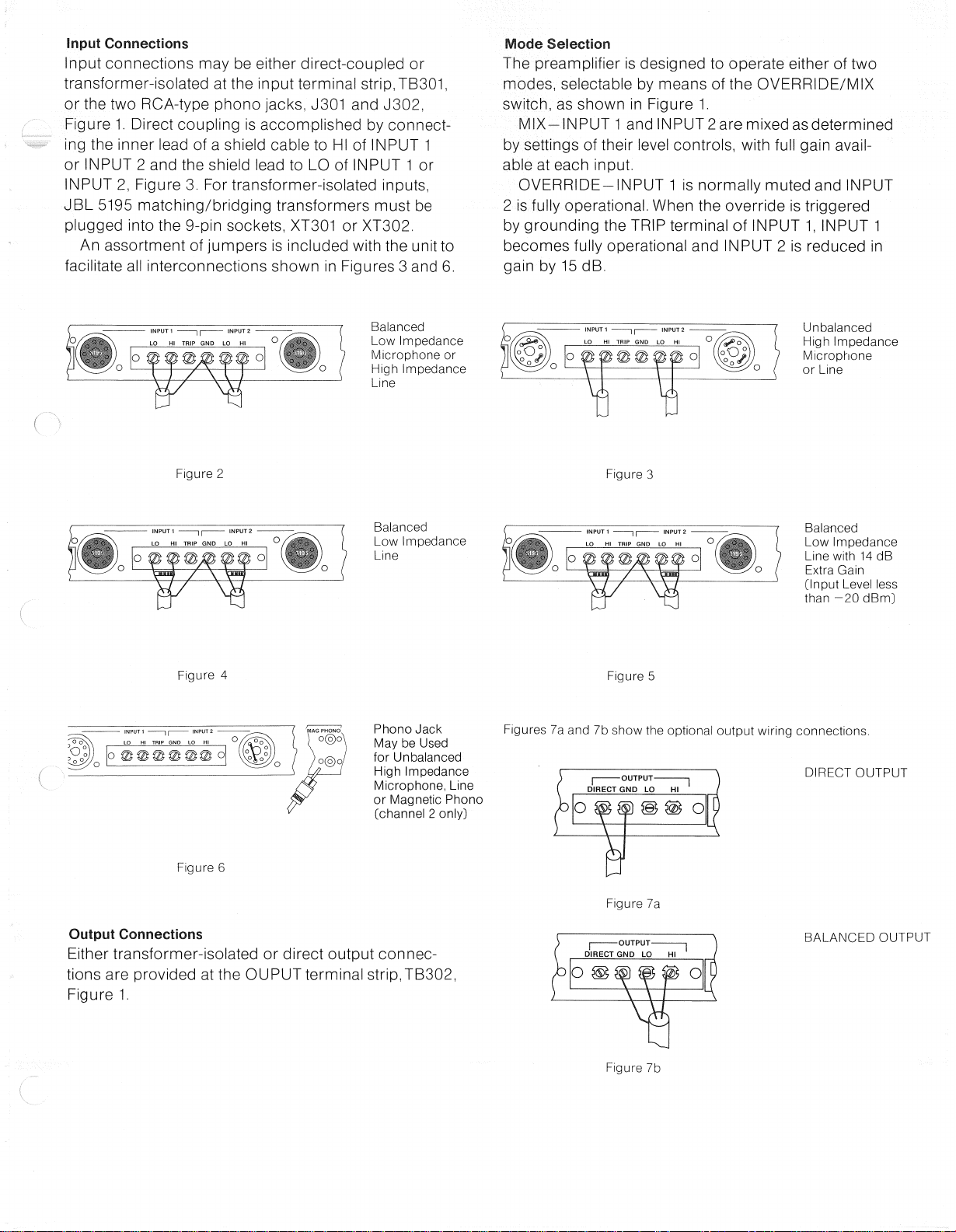
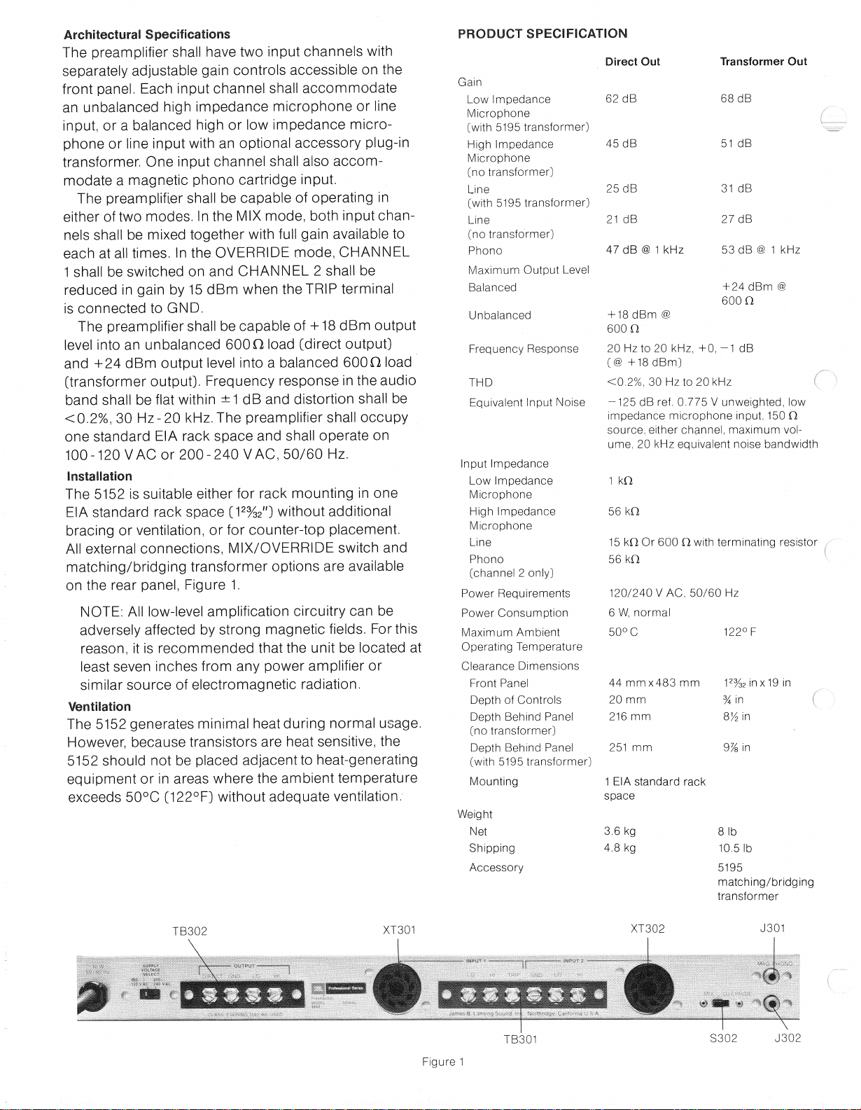
ArchitecturalSpecifications
The
preamplifiershallhavetwoinputchannelswith
separately
adjustablegaincontrols
accessible
onthe
front
panel.
Each
inputchannelshallaccommodate
an
unbalancedhighimpedancemicrophoneorline
input,ora balancedhighorlowimpedancemicro-
phoneorlineinputwithanoptional
accessory
plug-in
transformer.Oneinputchannelshallalsoaccom-
modatea magneticphonocartridgeinput.
The
preamplifiershallbecapableofoperatingin
eitheroftwomodes.IntheMIXmode,
both
input
chan-
nels
shallbemixedtogetherwith
full
gainavailableto
each
atalltimes.Inthe
OVERRIDE
mode,
CHANNEL
1
shallbeswitchedonand
CHANNEL
2 shallbe
reduced
ingainby15dBmwhenthe
TRIP
terminal
is
connectedtoGND.
The
preamplifiershallbecapableof+18dBm
output
level
into
anunbalanced600Oload[directoutput}
and
+ 24dBm
output
level
into
a balanced600Oload
(transformeroutput].Frequencyresponseintheaudio
bandshallbeflatwithin±1dBanddistortionshallbe
<0.2%,30Hz-20kHz.Thepreamplifiershalloccupy
onestandardEIArack
space
andshalloperateon
100-120
VACor200-240VAC,50/60Hz.
Installation
The
5152issuitableeitherforrackmountinginone
EIA
standardrack
space
(12%2"3
withoutadditional
bracingorventilation,orforcounter-topplacement.
Allexternalconnections,
MIX/OVERRIDE
switchand
matching/bridgingtransformeroptionsareavailable
ontherearpanel,Figure1.
NOTE:
Alllow-levelamplificationcircuitrycanbe
adversely
affectedbystrongmagneticfields.Forthis
reason,
itisrecommendedthattheunitbelocatedat
least
seven
inchesfromanypoweramplifieror
similar
sourceofelectromagneticradiation.
Ventilation
The
5152generatesminimalheatduringnormal
usage.
However,
becausetransistorsareheatsensitive,the
5152
shouldnotbeplacedadjacenttoheat-generating
equipmentorin
areas
wheretheambienttemperature
exceeds
50°C(122°F)withoutadequateventilation.
Figure
1
PRODUCT
SPECIFICATION
DirectOutTransformerOut
Gain
Low
Impedance62dB68dB
Microphone
(with5195transformer]
HighImpedance45dB51dB
Microphone
[notransformer]
Line
25dB31dB
[with
5195transformer]
Line
21dB27dB
(notransformer]
Phono47dB@1kHz53dB@ 1 kHz
Maximum
Output
Level
Balanced
+24dBm@
600
a
Unbalanced+18dBm@
600
O
Frequency
Response20Hzto20kHz,+0,-1dB
(@
+18dBm]
THD
<0.2%,30Hzto20kHz
Equivalent
Input
Noise-125dBref.0.775V unweighted,low
impedancemicrophone
input,
150O
source,
eitherchannel,maximumvol-
ume,20kHzequivalentnoisebandwidth
Input
Impedance
Low
Impedance1 kO
Microphone
HighImpedance56kO
Microphone
Line
15kOOr600O
with
terminatingresistor
Phono56kO
(channel
2 only]
Power
Requirements120/240V AC,50/60Hz
Power
Consumption6 W,normal
MaximumAmbient50°C 122°F
OperatingTemperature
Clearance
Dimensions
FrontPanel44mmx483mm12%2inx19in
DepthofControls20mm% in
DepthBehindPanel216mm8/2in
(notransformer]
DepthBehindPanel251mm9%in
(with5195transformer]
Mounting
1 EIAstandardrack
space
Weight
Net3.6kg8 lb
Shipping4.8kg10.51b
Accessory
5195
matching/bridging
transformer

InputConnections
Inputconnectionsmaybeeitherdirect-coupledor
transformer-isolatedattheinputterminal
strip,TB301,
orthetwo
RCA-type
phono
jacks,
J301
and
J302,
Figure
1.Directcouplingisaccomplishedbyconnect-
ingtheinnerleadofa shieldcabletoHIof
INPUT
1
or
INPUT
2 andtheshieldleadtoLOof
INPUT
1 or
INPUT
2,Figure3.Fortransformer-isolatedinputs,
JBL
5195matching/bridgingtransformersmustbe
plugged
into
the9-pin
sockets,
XT301
or
XT302.
An
assortmentofjumpersisincludedwiththeunitto
facilitateallinterconnectionsshownin
Figures
3 and6.
ModeSelection
The
preamplifierisdesignedtooperateeitheroftwo
modes,
selectablebymeansofthe
OVERRIDE/MIX
switch,
asshowninFigure1.
MIX-INPUT
1
and
INPUT
2 aremixedasdetermined
bysettingsoftheirlevelcontrols,with
full
gain
avail-
able
at
each
input.
OVERRIDE-INPUT
1 isnormallymutedand
INPUT
2
isfullyoperational.Whentheoverrideistriggered
bygroundingthe
TRIP
terminalof
INPUT
1,
INPUT
1
becomes
fullyoperationaland
INPUT
2 isreducedin
gainby15dB.
Balanced
Low
Impedance
Microphoneor
HighImpedance
Line
Unbalanced
HighImpedance
Microphone
or
Line
Figure
2
Figure
3
Balanced
Low
Impedance
Line
Balanced
Low
Impedance
Line
with14dB
Extra
Gain
[Input
Level
less
than-20dBm]
Figure
4
Figure
5
Figure
6
Phono
Jack
May
be
Used
forUnbalanced
HighImpedance
Microphone,
Line
orMagneticPhono
[channel
2 only]
Figures
7aand7bshowtheoptional
output
wiringconnections.
DIRECT
OUTPUT
OutputConnections
Either
transformer-isolatedordirect
output
connec-
tionsareprovidedatthe
OUPUT
terminal
strip,TB302,
Figure
1.
Figure
7a
BALANCED
OUTPUT
Figure
7b

The
following
proceduresaredesignedto
assist
inthe
isolationofmalfunctions.Theoperationsdescribed
shouldbeundertakenonlyafteraninvestigationofall
external
connectionsandadjustmentshasindicated,
beyondreasonable
doubt,
thattheproblemisactually
within
the
unit.
Component
Access
The
5152containsonlyoneprintedcircuitboard.All
componentsaremounteddirectlyonthecircuitboard
with
theexceptionofthe
output
transformer,power
transformer,
on/off
switch,
pilot
lamp,levelcontrols,
supplyvoltageselectswitch,
input
and
output
terminal
strips,
mix/overrideswitchandthe
9-pin
sockets.
To
reachthecircuitboardfortesting,servicingor
input
selection,onlythetopcovermustberemoved
(eightsheetmetal
screws}.
Removalofthecircuit
board
from
the
chassis
requires
popping
outsix
snaps.
VoltageConversion
The
5152canbeoperated
from
eithera 100-120VAC
or200-240V AC,50/60Hzsource.The
SUPPLY
VOLTAGE
SELECT
switch,
S301,
convertsthe
unit
from
oneoperatingvoltagerangetotheother.Usethe
following
procedurestoconvertthepreamplifiertoa
differentvoltagerange:
1.
Disconnectthe5152
from
thepowersource.
2.
Slidethe
SUPPLY
VOLTAGE
SELECT
switchtothe
appropriatelinevoltagerange.
WARNING
THIS
SECTION
OFTHEMANUAL
CONTAINS
SERVICE
INSTRUCTIONS
FOR
USEBY
QUALIFIED
SERVICE
PERSONNEL
ONLY.
3.
Changethelinecordandattachmentplugtomatch
thepowersourcereceptacleorusea 120-to-240V
adapter(notprovided}.Theattachmentplugand/or
linecordusedfor240V ACmodeintheU.S.,
Canada
and
Japan
shallbe
both
U.L.listedand
C.S.A.
Certified.Foruseinothercountries,linecord
selection
shouldbebasedonlocalregulations
governing240V AC50/60Hzsupplysource.
U.L.
and
C.S.A.
VoltageWiringCode
Country
Switch,Switch,Ground,
Wire
S301,
S201,E401Color
TerminalTerminal
U.S.
and1 - -
Black
Japan
- 1 - White
-- YesGreen
Europe
1 - — Blue
-1 — Brown
-- Yes
Green/-,
oilow
CAUTION:
This
unit
maybedamagedifoperated
with
thesupplyvoltageselectswitchsetincorrectly
forthelinevoltageapplied.
Selector
Switch
Table
1 showsthevarious
input
sources,
terminations
and
jumperoptionsforthe5152.SeeFigures2-6for
available
interconnections.
TABLE
1
InputSelector
Transformer
Switch
Position
Accessory
Socket
Jumper Termination
Input
Connector
(InternalAdjustment)
Transformer
Connections
Resistor
Balanced
Low
Impedance
Terminal
MIC
5195
None None
Microphone
Strip
Unbalanced
HighImpedance
Terminal
MIC
None
4-5
None
Microphone
Strip
7-9
Phono
Jacks
MIC
None 3-9 None
(Channel
2 only)
Balanced
HighImpedance
Terminal
LINE
5195
None None
Line
Strip
Balanced
Low
Impedance
Terminal
LINE
5195
None 620-ohm
Line
Strip
1/2-watt
Balanced
Low
Impedance
Line
with
14dB
Terminal
MIC
5195
None 1800-ohm
Extra
Gain
Strip
K-watt
(Input
Level
Less
Than
-20dBm}
Unbalanced
HighImpedance
Terminal
LINE
None
4-5
None
Line
Strip
8-9
Phono
Jacks
LINE
None 3-9 None
(Channel
2 only)
Magnetic None
Phono Phono
Jacks
PHONO
None 3-9 None
(Channel
2 only]

OutputConversion
For
150O
output,
the
following
procedureshouldbe
used
toparallelthewindingsofthe
output
transformer,
T402,
Figure8.
1.
Disconnectthe
unitfrom
thepowersource.
2.
Clipthe
BLUE
and
VIOLET
output
transformerleads
from
theprintedcircuitboardatpoints#27and#28.
3.
Solderthe
BLUE
transformerwiretothe
GREEN
wireattheOUTPUTterminalstrip,TB302,
markedHI.
4.
Solderthe
VIOLET
transformerwiretotheG
RAY
wire
atthe
OUTPUT
terminalstrip,
TB302,
markedLO.
The
5152hasbeendesignedsothat
both
thedirect
andtransformeroutputsmaybeusedsimultaneously.
ProofofPerformance
Allperformancechecksarein-cabinetproceduresto
beusedforcheckingspecificationsafterrepairorfor
incomingqualitycontrolinspection.
NOTE:
Allmeasurementsshouldbemade
with
the
unit
andtestequipmentpowercordsconnectedtoa
normal120VACor240V AC50/60Hzlinesource.
WARNING
THISSECTION
OFTHEMANUAL
CONTAINS
SERVICEINSTRUCTIONS
FOR
USEBY
QUALIFIEDSERVICE
PERSONNEL
ONLY.
FIGURE
10,
REVERSE
RIAA
EQUALIZATIONNETWORK
DONOTUSE
SHIELDEDCABLE
ATTHE
OUTPUT
OF
THE
FILTER;STRAPDIRECTLY
TOTHE
INPUT
OF
THE
VOLTMETER,
ACVOLTMETER
ToMIC
CHANNEL
UNDER
TEST
FIGURE
12,40dB,
600
n PAD
The
following
testequipmentisrecommended:
AUDIO
TESTOSCILLATOR
HARMONIC
DISTORTIONANALYZER
40
dBPAD[150O)
REVERSE
RIAA
EQUALIZATION
NETWORK
20
kHz
FILTER
ALTERNATE
40dBPAD[600O)
Krohn-Hite4100,orequivalent.
Hewlett-Packard
model333A,orequivalent.
See
Figure9
See
Figure10
See
Figure11
See
Figure12
Figure
8.
FIGURE
9,40dB,
150
n PAD
HEWLETT
PACKARD
333A
OR
331A
FIGURE
11,20KHZ
FILTER
ALTERNATEOSCILLATORSETUP:
Z=600n
20
KHZ
FILTER
OSCILLATOR
IN ToPHONOIN
150A BAL
KROHN-HITE
4100
To
MIC
CHANNEL
UNDER
TEST
OSCILLATOR
40
dBPAD
KROHN-HITE
4100
OSCILLATOR 40dB
PAD

Frequency
Response
(20
Hz-20kHz,+0,-1dB@ +18dBm,
into
600O
Ref.
1
kHz.)
Table
2 outlinesthetestset-upandsequencefor
measuringfrequencyresponseofthe5152.
JUMPERS
Figure13
WARNING
THIS
SECTION
OFTHEMANUAL
CONTAINS
SERVICE
INSTRUCTIONS
FOR
USEBY
QUALIFIED
SERVICE
PERSONNEL
ONLY.
4.
Setthe
CHANNEL
1 or
CHANNEL
2 levelcontrol,
dependingonwhichchannelisundertest,to
maximum.
5.
Settheoscillatorlevelfora +18dBm(directoutput)
or+24dBm(transformeroutput).
6.
Measurethe
distortion
ofthepreamplifierat30Hz,
200
Hz,2 kHzand20kHz.
HEWLETT
PACKARD
333A
FIGURE
14,THD
TEST
SET
UP
MicrophoneEquivalentNoise
(-125
dBRef.0.775V unweighted,150Osource
20
kHzequivalentbandwidth).
Using
thetestset-up,Figure11or12:
1.
Setthe
MIC/LINE
or
PHONO/LINE/MIC
switch
toMICandthe
MIX/OVERRIDE
switchtoMIX.
2.
Installa 5195transformer
into
INPUT
1 or
INPUT
2.
3.
Setthe
CHANNEL
1 or
CHANNEL
2 levelcontrol
tomaximumandthechannelnotundertestto
minimum.
4.
Settheoscillatorto2 kHzandadjustthe
output
level
ofthe5152to0 dBm.
5.
Measurethe
input
signal.Typicalreadingsare-71
dB,
indicatinga gainof71dB.
6.
Installthe20kHz
filter,
Figure11.
7.
Disconnecttheoscillator
from
thepreamplifier.
8.
Measurethenoiselevelatthe
output
ofthe5152.
Typical
readingsare-54dBm.
9.
Addthe
input
levelandnoisemeasurementto
calculate
theequivalent
input
noise.
EXAMPLE
-71dBRef.0 dBm
INPUT
LEVEL
-54
dBRef.OdBm
NOISE
LEVEL
-125
dBRef.OdBm
EQUIVALENT
INPUT
NOISE
10.
Thecalculatedequivalent
input
noisefigureshould
be-125dB(Ref.0 dBm)orbetter.
DC
VoltageMeasurements
AllDCvoltagemeasurementsare
with
respectto
groundandaremadeusinga Fluke8000A
with
a line
voltageof120V AC.
Voltages
shown
with
tworeadingsontheschematic
indicatethetwostatesofthe
TRIP
DETECTOR
and
FET
GATE
whenproperlyoperating.
EXAMPLE
TRIP
DETECTOR
+
0.460V NOT
GROUNDED
+
86.9mVTRIP
DETECTOR
GROUNDED
TABLE
2
AC
VOLTMETER
OR
HARMONIC
DISTORTION
ANALYZER
Figure
1
+ THDtestsetup.
THD
(<0.2%,30Hz-20kHz).
Using
thetestset-up,Figures9 and14:
1.
Setthe
MIC/LINE
or
PHONO/LINE/MIC
switch
to
LINE.
2.
Setthe
MIX/OVERRIDE
switchtoMIX.
3.
Installjumpersbetweenterminals#4and#5and
betweenterminals#8and#9ofeach
9-pin
socket,
XT301
and
XT302,
Figure13.
NOTE:
TouseTable2,read
down
and
across.
Numbersunder
LINE,
MICand
PHONO
representtestsequence.
Frequency
ResponseTestand
OperationalSequence.
Line
LineMic Phono
Connecttestoscillatorto
input.
1 1
Connecttestoscillatorto
input
using
1
Figure9 orFigure12.
Connecttestoscillatorto
input
using
1
Figure10.
Set
MIC/LINEorPHONO/LINE/MIC
2
switchtoMIC.
Set
MIC/LINEorPHONO/LINE/MIC
2 2
switchto
LINE.
Set
PHONO/LINE/MICswitchtoPHONO.
2
ConnecttheAC
voltmeter
anda 620O,
3 3 3
1
W loadresistoracross
output
terminals
marked
DIRECT
andGND.
ConnecttheAC
voltmeter
anda 620O,
3
1
W loadresistoracross
output
terminals
markedHIandLO.
Set
CHANNEL1 orCHANNEL2 level 4 4 4
control
tomaximum.Setthetestoscillator
to2 kHzandadjustthe
amplitude
toindicate
+
18dBmacrossthe
DIRECT
andGND
terminalsofthe
OUTPUT
strip.
Set
CHANNEL1 orCHANNEL2 level 4
control
tomaximum.Setthetestoscillator
to2 kHzand
adjusttheamplitudeto
indicate
+24dBmacrosstheHIandLOterminals
ofthe
OUTPUT
strip.
Voltagegainofthesystemcanbechecked
5 5 5 5
by
substituting
thevalueintheformula:
Av(db)=20Loq10ClO
Input
voltageofthesystemcanbe
measuredbyconnectingtheAC
voltmeter
6 6 6 6
attheINPUTterminals.

JBL
ProfessionalDivision
James
B.
LansingSound,
Inc.,
8500BalboaBoulevard,
Northridge,
California91329,U.S.A.
50705
PTM515211/78
PRINTED
IN
U.S.A.
Table of contents
Other JBL Amplifier manuals