JBL 6011 Manual

JBL
6011/6012
INSTALLATION
ANDSERVICE
MANUAL

OwnersInstructions ProductSpecifications
ArchitecturalSpecifications
Theamplifiershallbesinglechannelwithaninputgain
controlandanoutputlevelmeteronthefrontpanel.
Theamplifiershallaccommodateanunbalancedhigh
impedanceinput,ora balancedlowimpedanceinput
withanoptionalplug-inaccessorytransformer.
Theamplifiershallbecapableofdeliveringa
min-
imumof100W,continuoussinewave,20Hz-20kHz,
intoa 4 O
load.
(6011:
Theamplifiershallincorporate
anoutputtransformerallowingfullpoweroperation,
35Hz-20kHz,intoan8 Q,16Cl or70.7V lineaswell
asa directoutputterminalfora 4 O load.](6012:No
outputtransformerandonlya directoutputterminal
shallbeprovided,butitshallbepossibletoinstallan
outputtransformereasilyatanytime.}
Theamplifiershallhave< 0.2%THD,20Hz-20kHz,
@100W,directoutput.
(6011:
Theamplifiershallhave
<0.2%THD,35Hz-20kHz,@ 100W,transformer
output.}Frequencyresponseshallbe± 0.5dB,
20Hz-20kHz,@ 1 W.Powerbandwidthshallbe
10Hz-40kHz.
Constructionoftheamplifiershallbemodular.The
entireamplifiercircuit,exceptforthepowersupply
(6011:
andoutputtransformer}shallbemountedon
asinglecircuitboardattachedtotheheatsink,which
assemblyshallberemovablefromtheunitwiththe
mainframestillmountedina rack.Cablesconnecting
thecircuitboardtothemainframeshallbeofa length
sufficienttoallowremovaloftheboardwithoutdis-
connectionandshalldisconnecteasilyattwoplugs.
TheamplifiershalloccupythreestandardEIArack
spacesandshalloperateon120/240VAC,50/60Hz.
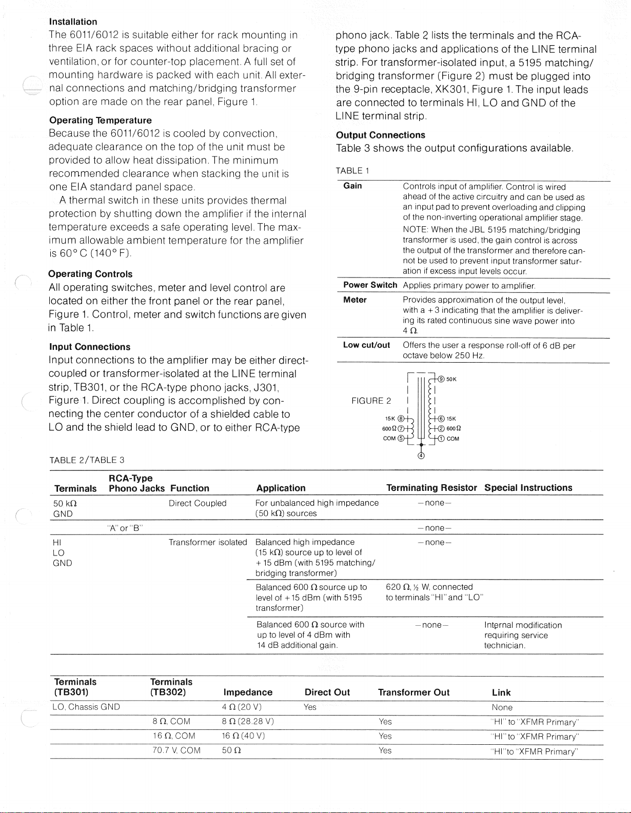
LOCUT/OUT
SWITCH(S301)
TRANSFORMEROUTPUT
TERMINALSTRIP(TB302]
LINETERMINAL
STRIP(TB301]
OPTIONALMATCHING/BRIDGING
TRANSFORMERINPUTSOCKET(XK301]
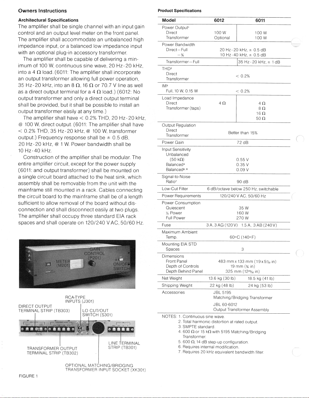
Model 6012 6011
PowerOutput1
Direct 100W 100w
Transformer Optional 100w
PowerBandwidth
Direct-Full 20Hz-20kHz,± 0.5dB
-% 10Hz-40kHz,± 0.5dB
Transformer—Full 35Hz-20kHz,± 1 dB
THD2
Direct
Transformer <0.2%
IM3
Full,
10W,0.15W <0.2%
LoadImpedance
Direct 4a 4a
Transformer[taps] 8a
16a
50a
OutputRegulation
Direct
Transformer Betterthan15%
PowerGain 72dB
InputSensitivity
Unbalanced
(50kO) 0.55V
Balanced4
0.35V
Balanced6-6
0.09V
Signal-to-Noise
Ratio7 90dB
Low-CutFilter 6dB/octavebelow250Hz,switchable
PowerRequirements 120/240VAC,50/60Hz
PowerConsumption
Quiescent 35W
y3Power 160W
FullPower 270W
Fuse 3A,3AG(120V)1.5A,3 AB(240V)
MaximumAmbient
Temp. 60°C(140°F)
MountingEIASTD
Spaces 3
Dimensions
FrontPanel 483mmx 133mm(19x5%2in]
DepthofControls 19mm[%in]
DepthBehindPanel 325mm
(1225/32
in)
NetWeight 13.6kg(30lb) 18.5kg(41lb)
ShippingWeight 22kg(48lb) 24kg(53lb)
Accessories JBL5195
Matching/BridgingTransformer
JBL60-6012
OutputTransformerAssembly
NOTES:
1.Continuoussinewave.
2.
Totalharmonicdistortionatratedoutput.
3.SMPTEstandard.
4.
600a or15kawith5195Matching/Bridging
Transformer.
5.600a,14dBstep-upconfiguration.
6.Requiresinternalmodification.
7.Requires20kHzequivalentbandwidthfilter.
FIGURE1
DIRECTOUTPUT
TERMINALSTRIP(TB303)
RCA-TYPE
INPUTS(J301)

Installation
The6011/6012
is
suitableeither
for
rackmounting
in
three
EIA
rackspaceswithoutadditionalbracing
or
ventilation,
orfor
counter-topplacement.
A
full
setof
mountinghardware
is
packedwitheachunit.
All
exter-
nalconnections
and
matching/bridgingtransformer
option
are
made
onthe
rearpanel,Figure
1.
OperatingTemperature
Because
the
6011/6012
is
cooled
by
convection,
adequateclearance
onthetopofthe
unitmust
be
provided
to
allowheatdissipation.
The
minimum
recommendedclearancewhenstacking
the
unit
is
one
EIA
standardpanelspace.
Athermalswitch
in
theseunitsprovidesthermal
protection
by
shuttingdown
the
amplifier
ifthe
internal
temperatureexceeds
a
safeoperatinglevel,Themax-
imumallowableambienttemperature
forthe
amplifier
is
60°C
(140°
F).
OperatingControls
Alloperatingswitches,meter
and
levelcontrol
are
located
on
either
the
frontpanel
orthe
rearpanel,
Figure1.Control,meter
and
switchfunctions
are
given
inTable
1.
InputConnections
Inputconnections
tothe
amplifier
maybe
eitherdirect-
coupled
or
transformer-isolated
atthe
LINEterminal
strip,
TB301,
orthe
RCA-typephonojacks,J301,
Figure1.Directcoupling
is
accomplished
by
con-
necting
the
centerconductor
ofa
shieldedcable
to
LO
andthe
shieldlead
to
GND,
orto
eitherRCA-type
phonojack.Table
2
lists
the
terminals
andtheRCA-
typephonojacks
and
applications
ofthe
LINEterminal
strip.
For
transformer-isolatedinput,
a 5195
matching/
bridgingtransformer(Figure
2)
must
be
pluggedinto
the9-pinreceptacle,
XK301,
Figure
1.
The
inputleads
areconnected
to
terminalsHI,
LOandGNDofthe
LINEterminalstrip.
OutputConnections
Table
3
shows
the
outputconfigurationsavailable.
TABLE
1
Gain
Controlsinput
of
amplifier.Control
is
wired
ahead
ofthe
activecircuitry
andcanbe
used
as
aninput
padto
preventoverloading
and
clipping
of
the
non-invertingoperationalamplifierstage.
NOTE:
When
theJBL5195
matching/bridging
transformer
is
used,
the
gaincontrol
is
across
theoutput
ofthe
transformer
and
therefore
can-
not
be
used
to
preventinputtransformersatur-
ation
if
excessinputlevelsoccur.
PowerSwitchAppliesprimarypower
to
amplifier.
MeterProvidesapproximation
ofthe
outputlevel,
with
a + 3
indicatingthat
the
amplifier
is
deliver-
ing
its
ratedcontinuoussinewavepowerinto
4
a.
Lowcut/outOffers
the
user
a
responseroll-off
of6 dBper
octavebelow
250Hz.
Terminals RCA-Type
PhonoJacks Function Application TerminatingResistor
Special
Instructions
50
kO
GND DirectCoupled Forunbalancedhighimpedance
(50
kCl)
sources
-none—
"A"or"B"
-none
—
HI
LO
GND
Transformerisolated Balancedhighimpedance
(15
kO)
source
upto
level
of
+
15dBm
(with
5195
matching/
bridgingtransformer)
-none-
Balanced
600O
source
upto
level
of+15dBm
(with
5195
transformer)
620
O,y2W,
connected
toterminals"HI"and
"LO'
Balanced
600O
sourcewith
up
to
level
of4 dBm
with
14
dB
additionalgain.
—
none-Internalmodification
requiringservice
technician.
Terminals
(TB301) Terminals
(TB302) Impedance Direct
Out
Transformer
Out
Link
LO.
Chassis
GND
4
O
(2.0
V)
Yes None
8
0,COM
80(28.28
V)
Yes "HI"to"XFMRPrimary"
16O,
COM
16
0(40V)
Yes "Hl"to"XFMRPrimary"
70.7V,
COM
50
O
Yes "HI"to"XFMRPrimary"
FIGURE
2
TABLE2/TABLE
3

ServiceandMaintenanceInstructions
Thefollowingproceduresaredesignedtoassistinthe
isolationofmalfunctions.Theoperationsdescribed
shouldbeundertakenonlyafteraninvestigationofall
externalconnectionsandadjustmentshasindicated,
beyondreasonabledoubt,thattheproblemisactually
withintheamplifier.
WARNING:Disconnecttheamplifierfromthepower
sourcebeforeperformingserviceoperationsor
replacingcomponents.
VoltageConversion
Eitheramplifiercanbeoperatedfromeithera 120V AC
or240V AC,50/60Hzsource.Thelinevoltageselector
terminalstrip,
TB401,
Figure3,changestheprimary
connectionsofthepowertransformer.Usethefollow-
ingproceduretochangethevoltagerange:
1.
Removethe10screwswhichholdthetopcover
tothechassis.
2.
Toconvertfrom120VACto240VAC,removethe
twoterminalstripjumpers,Figure4a.Installone
jumperonlyperFigure4b.
3.Changethelinecordand/orattachmentplugto
matchthesupplysourcereceptacle,orusea 120V
to240VACadapter(notprovided).Theadapter
aswellasthepowersupplycordand/orattachment
plugusedforthe240VACmodeintheU.S.,
CanadaandJapanshallbebothULListedand
CSACertifiedforusewithsaidpowersource
receptacleandwiredperTable4.Foruseinother
countries,adapter,linecordand/orattachment
plugselectionshallbebasedonlocalregulations
governing240VAC,50/60Hzsupplysources.
4.
Changethelinefusefroma 3A,3AGtypetoa
1.5A,3AB.
WARNING
THISSECTIONOFTHEMANUAL
CONTAINSSERVICEINSTRUCTIONS
FORUSEBYQUALIFIEDSERVICE
PERSONNELONLY.
FIGURE4A
120VAC
FIGURE4B 240VAC
FIGURE3
TB401
TABLE4
LineCordConnections
TerminalStrip FuseHolder GroundLug
Country WireColorCode (TB401) (CenterTerminal) (Figure3)
U.S.,CanadaandJapan Black — Attached —
White Attached --
Green - - Attached
Europe Blue Attached —
Brown Attached
Green/Yellow -Attached
120 240 120
120 240 120

WARNING
THISSECTION
OFTHE
MANUAL
CONTAINSSERVICEINSTRUCTIONS
FOR
USEBY
QUALIFIEDSERVICE
PERSONNELONLY
Item JBLPart
No.
Qty. Description
1 52886 1 knob
2 55651 1 panel
3 55098 1 meter
4 51580 7 10-32Keps3
5 10997 10
4-40x%
Phillips-headmachinescrew
6 54959 1 lamp
7 54969 1 knob
8 4 3
mm1
9 4 3
mm1
10 4 3
mm1
11 89508 1
2
12 89508 1 10-32Keps2
13 11908 1
No.
6
inter-toothwasher
14 54968 1 6-32
hex
spacer
15 55523 1 switch
16 55901 1 poweramplifierboard
17 55153 4
6-32xY2
hex
washerheadscrew
*NOTES:
1.NoJBL
replacement
forthe3 mmset.
2.
Unit
may
haveeither
a
Keps
nut,
Keps
nutand
washer
or
Keps
nut,
splitwasher
and
flatwasher.
3.Keps
nut
locked
to
panelstudwithLoctite.

WARNING
THISSECTION
OF
THEMANUAL
CONTAINSSERVICEINSTRUCTIONS
FOR
USEBY
QUALIFIEDSERVICE
PERSONNELONLY.
InstrumentType RequiredCharacteristic RecommendedInstrument
TestOscillator FrequencyRange:
20
Hz-20
kHz
Distortion:
<0.001%
Output:1
V
RMS
Min.
SoundTechnology
Model1700
A
DistortionAnalyzer Measurable
to
0.002% SoundTechnology
Model1700A
Multimeter Accuracy:0.1%reading
+1
digit
DCRange:
±
199.9
mVto±
1199
V
Resistance:±0.2%
of
reading
+
1
digit
InputImpedance:
10MO
FlukeModel8000
A
OutputLoadResistors 100W,
4 O
and
8 n
non-inductivetype,1% DaleNH-100
ResistorDecade
Box
1
Q-1
kOMin.
VariableAutotransformer Capable
of
supplyingmin.
of500W
over
a
range
of
90-136
V.
1.
If
autotransformerdoes
not
have
anAC
voltmeter
to
indicate
outputvoltage,monitor
the
outputwitheither
a
multimeter
orAC
voltmeter.
2.
If
autotransformerdoes
not
have
a
wattmeter,
a
wattmeter
capable
of
indicating15
-
270
W
will
be
required.
GenRadW5MT3W
RecommendedTestEquipment
Thefollowingtestprocedures
are
requiredafter
anIC,
drivertransistor,biasnetworkdiode,thermistor,
or
outputdevice
is
replaced:
BiasAdjustment
Verifythatthedistortion
at20
kHz,100W,
isthe
same
as
20
kHz
at
1
W
andthatthestableidlepower
is
30-35W.
If
not,
the
followingprocedure
is
required:
1.
SubstituteresistorR37with
a
decade
box.
2.
Adjusttheamplifier
for
1
W at20kHz.
3.Adjustthedecade
for
minimumdistortion
and
sub-
stitute
R37
with
the
closest
EIA
standardresistor.
4.
Verifydistortion
at
100
W
and1
W.
NOTE:
Amplifiermust
be
warmbeforeperforming
distortionmeasurements
or
adjustments.
DCOffsetAdjustment
Connectthemultimeter
to
testpoint
#2onthe
circuit
board.
With
the
meter
setat
thelowest
DC
voltage
range(mV),adjust
theDC
NULLcontrol,R10,
fora
minimum
DC
voltage,
0 ± 25mV.
NOTE:
Amplifiermust
be
warmbeforemaking
adjustments.
Installation
of
OptionalTransformer
[option
on
6012}
Toinstall
the
optionaloutputtransformerFigure
5,
[ModelNo.60-6012):
1.
Remove
the
heatsink/circuitboardassembly.
2.
Place
the
optionaloutputtransformer
inthe
corner
ofthechassisandsecure
itat
thefourholes
inthe
bottom
of
thechassiswith
the
hardwareprovided.
3.Attach
the
Molexconnectortothematingconnector
oftheamplifier.
4.
Remove
the
coveroverthecutout
forthe
TRANS-
FORMEROUTPUTterminalstrip.Slip
thenew
terminalstrip
of
theoutputtransformerthrough
the
cutoutandorient
itso
thattheGRAYwire
isthe
COM.
Screw
the
terminalstrip
in
placewith
the
screwsthatheld
the
cover.
NOTE:
If
theoutputtransformer
istobe
used,install
aLINKbetween
LOandHIof
theDIRECTOUTPUT
terminalstrip,Figure
1.
14
dBAdditionalGainConversion
14
dBof
additionalinputsensitivity,using
the
optional
JBLModel5195matching/bridgingtransformer,
can
beoffered
tothe
user
by
removing
the
REDwire
con-
nected
topin#8of
the9-pinreceptacle,
XK301,
and
reconnecting
ittopin#7.
20
kHz
Equivalent
BandwidthFilter
INPUT
OUTPUT

Performanceplotofa typicalunit WARNING
THISSECTIONOFTHEMANUAL
CONTAINSSERVICEINSTRUCTIONS
FORUSEBYQUALIFIEDSERVICE
~PERSONNELONLY
NGTBS-
GraphsrecordedusingRadiometersBKF10REC61S2andSMU401
Frequencyresponseanddistortionmeasurementsmadeusinga
constantinputleveltotheamplifierundertest
NOTES
GtaphsrecoidedusingRadiometersBKF10REC61S2andSMU401
Frequencyresponseanddistortionmeasurementsmadeusinga
constantinputleveltotheamplifierundertest

JBL ProfessionalDivision
JamesB.LansingSound,Inc.,8500BalboaBoulevard,Northridge,California91329
U.S.A.
56404
PTM
6011/12
10/78PrintedinU.S.A.
This manual suits for next models
1
Table of contents
Other JBL Amplifier manuals

JBL
JBL 1201.1 User manual

JBL
JBL VT4888DP-AN User manual

JBL
JBL GTO Series 601.1 User manual

JBL
JBL MA6004 User manual

JBL
JBL MS-A5001 User manual

JBL
JBL GTO 75.2II User manual

JBL
JBL Synthesis S650 Operating and installation instructions

JBL
JBL STADIUM 4 User manual

JBL
JBL 6230 User manual

JBL
JBL GTO4000 User manual