JBL Power P42c User manual

Automotive Component Systems
P–42c, P–52c, P–62c Owner’s Manual
GENUINE JBL
P-42c, 52c, 62c OM 7/14/98 11:32 AM Page 1

02
Thank you for purchasing a JBL
Power Series™ 2-Way Component
System. We’ve organized this manual to
make your installation as simple and
trouble-free as possible. Please read
through it completely before proceeding.
If, after having read it, you decide that
you would rather leave installation to a
professional, consult your JBL Power
Series Dealer.
Autosound at Its Best
Your JBL Component System is built to
meet the same rigorous standards of
construction and performance that have
long established JBL’s renowned home
and professional speaker systems.
Your Component System has been
designed using a combination of tech-
nologies that bring high value to high
performance. The tweeter dome used in
your Component System tweeter is man-
ufactured from a proprietary material
known as Titanium Composite. This
material combines the control and
damping of an advanced polymer with
the reinforcing stiffness of vapor-
deposited titanium to prevent breakup at
high levels.
Similarly, the woofer cones are manufac-
tured with a proprietary injection-molded
titanium-composite cone in order to
deliver the clarity and effortless power
that have made JBL famous. This cone is
suspended by a heavy butyl-rubber
surround, which serves to absorb any
remaining cone resonances for the
clearest, most articulate reproduction of
voices and other mid-range sounds.
As a bonus, the butyl-rubber surround is
impervious to temperature extremes and
humidity, making it ideal for automotive
applications.
By following the installation recommen-
dations and suggestions included in this
manual, you will be assured of many
years of trouble-free enjoyment from
your Power Series loudspeakers.
Component System Parts
Your new Component System consists of
a neodymium magnet tweeter and either
a 4", 5-1/4", or 6-1/2" midwoofer. This
system has also been supplied with an
outboard crossover network to provide
precision division of frequencies
between the two components. Figure 2 is
an illustration of the proper wiring proce-
dure of the Component System.
Important Paperwork
Before proceeding, be sure to put the
sales receipt from your JBL Component
System purchase in a safe place. It is nec-
essary to validate your Limited Warranty.
Having access to the receipt is also valu-
able for insurance purposes and when it
comes time to resell your vehicle.
Tweeter Installation
The tweeter has been supplied with both
surface- and flush-mount brackets.
Figures 1 and 2 show the proper way to
flush- and surface-mount the tweeter.
The mounting hole diameter of the flush-
mount frame is 1-7/16".
1
2
3
FLUSH MOUNT
Figure 1
P-42c, 52c, 62c OM 7/14/98 11:32 AM Page 2

03
CONNECT
TO
AMPLIFIER
SURFACE MOUNT
FREQUENCY
DIVIDING
NETWORK
1
2
3
2) LIFT
1) PUSH
REMOVING
COVER
+
–
Trim Ring
Car Door
Grille Screen
Figure 2a. Grille
mounting
Figure 2
Typical installation
of the P-42c and
P-52c woofers
with grilles as shown
in Figure 2a.
Installation of the P-42c woofer as shown in Figures 4a and 4b.
Removable Mounting Ears on
P-42c
Bend up and down repeatedly
to break off or use tin snips.
• Some Toyota installations may require mounting ears to be
removed from opposite sides.
• Some European car installations may require all
four ears to be removed.
Figure 4a
Mounting Ears Removed
Figure 4b
Two-Screw Mounting Configuration
P-42c, 52c, 62c OM 7/14/98 11:32 AM Page 3

04
Mounting
Hooks
Mounting
Ring
Foam
Gasket
Mounting
Slots
Rotate
to
Lock
Rotate
to Lock
Rotate
to Lock
Slots for
Mounting
Hooks
Mounting
Hooks
Mounting
Ring
Foam
Gasket
Mounting for US 6-1/2"
Honda/Toyota
Factory Location
Match Notch on
Speaker with
Notch on Trim Ring
Grille
Screen
Hole
Cutout
Grille
Trim Ring
Figure 5b
Figure 5c
Front View
Custom Door Mounting with Grille
Screw Patterns Fit DIN (European) 165/170mm
Mounting Holes.
Rear View
Figure 5a
Installation of the P-62c woofer with the
Intermount II (pat. pend.) mounting system is
shown in Figures 5a, b, c.
Hole Cutout
Clips
Mounting
Surface
Figure 5d
Figure 5e
Mounting the P-62c woofer in
165/170mm DIN (European) installa-
tions using the Intermount II™ clips
shown in Figures 5d and 5e.
Front Mounting
Rear Mounting
P-42c, 52c, 62c OM 7/14/98 11:32 AM Page 4

05
Component Placement
Because of the JBL Component System’s
small size and extremely versatile mount-
ing options, there are an almost infinite
number of placement options to achieve
excellent sound quality in any vehicle.
Please consider the following state-
ments to help you get the most from
your system.
1. The most spacious stereo image is
achieved when the left and right
speaker systems are placed as far apart
as possible.
2. The best center image will be achieved
when the distance from the left speaker
and the right speakers are as equal as
possible from your listening position.
This is most easily achieved by placing
the speakers as far forward as possible.
3. Treble is directional in nature. This
means that high frequencies are reduced
as you move off the tweeter's axis. The
angle mounts will allow the tweeters to
be pointed across the car to the listener
on the opposite side. This will make each
listener slightly off-axis to the tweeter that
is closest to that listener, which helps to
compensate for the fact that the listener is
always closer to one tweeter than to the
other (see Figure 6).
The best system integration is achieved
when the tweeter is mounted close to the
midwoofer speaker. This helps smooth
the transition from the midrange and
tweeter at the crossover point.
Choosing mounting locations that satisfy
all of the above criteria will provide the
most satisfying performance.
Figure 6
System Design
There are a variety of system options
available with the Component System.
The simplest configuration is to use them
full range with their built-in passive
crossovers by connecting them to the out-
put of a head unit or an amplifier (Figures
7 and 8).
A more advanced system design can be
achieved by adding a Decade,™ GT,
Power, GTi, or equivalent subwoofer
to your component system. In this case
the component system will be used as
high and midbass frequency drivers and
should have their extremely low frequen-
cies blocked by electrical means. Active or
passive crossovers can be used in order
to achieve the best system fidelity and
widest dynamic range. Crossover fre-
quency recommendations are given in
the Specifications.
Left
Channel
Power
Tweeters
Power component system
connected to speaker outputs of
a high powered head unit
Power
Midwoofers
Left
Right
Channel
Right
Amplifier output
set at full range or
high passed at f > 80Hz
Left
Channel
Power
Tweeters
Power component system
connected to amplifier
Power
Midwoofers
Left Right
Figure 8
Figure 7
P-42c, 52c, 62c OM 7/14/98 11:32 AM Page 5

06
Installation Warnings
and Tips
• Be careful not to cut or drill into fuel
tanks, fuel lines, brake or hydraulic lines,
vacuum lines or electrical wiring when
working on your vehicle. Inspect behind
panels before you cut or drill.
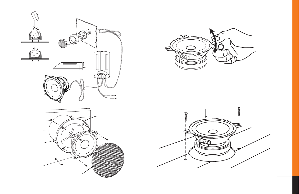
• Make sure that the midwoofer will
physically fit in the mounting location. If
door mounting, check for adequate
clearance with the window in both
rolled-up and rolled-down positions as
well as for interference with window
crank and power window mechanism.
If mounting elsewhere, check for
clearance around rear deck torsion bars,
glove box or other structural elements.
• Do not mount speakers where water
may splash on the cones.
• Make sure that it will be easy to run
connecting wires to the speakers. Trace
speaker wire paths before you undertake
mounting.
• Always disconnect the ground wire
from the battery before doing any work
on the vehicle.
CAUTION: Fuel tanks are located
directly beneath the rear deck in
some cars. Check for adequate speaker
basket clearance before considering this
location!
A Note on Power Handling
As a result of their high efficiency, all JBL
loudspeakers will produce reasonable vol-
ume levels in the automotive environ-
ment using very little amplifier power.
However, the use of a small amplifier to
attain very high volume levels could lead
to over-driving the amplifier. This will
generate high distortion levels which can
easily damage loudspeakers, even if the
rated power of the amplifier is below the
rated maximum power handling of the
loudspeaker!
As a general rule, do not turn up the vol-
ume control past the point where you
hear distortion in the form of either signal
distortion from an overdriven amplifier or
mechanical noise from an overstressed
speaker.
For the best performance and system reli-
ability, you should select an amplifier
with an output rating greater than the
maximum power likely to be used to gen-
erate the desired volume levels.
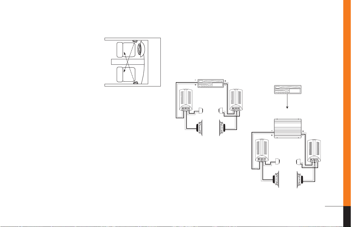
If you want your system “Loud + Clear,”
we suggest that you step up to a JBL
power amplifier which has an RMS power
rating equal to, but not exceeding the
Maximum Recommended Amplifier
Power
listed in the specifications of your
specific JBL speaker. This margin of
reserve power will ensure that the ampli-
fier will not attempt to deliver more
power than its design allows. Your dealer
will be happy to point out which high
power JBL amplifiers are optimum for
your application and listening habits.
Following these guidelines will provide
virtually distortion-free sound reproduc-
tion and long loudspeaker life.
WARNING: Playing loud music over
120dB can permanently damage your
hearing. The maximum volume levels
achievable with JBL components and
high power amplification may exceed
safe levels for extended listening.
When listening at high volume levels,
always use hearing protection or turn
the volume down!
P-42c, 52c, 62c OM 7/14/98 11:32 AM Page 6

07
Specifications
Component Systems
Model P-62c P-52c P-42c
Power Series Automotive Power Series Automotive Power Series Automotive
6-1/2" 2-Way Component 5-1/4" 2-Way Component 4" 2-Way Component
System System System
1/2" titanium-composite 1/2" titanium-composite 1/2" titanium-composite
neodymium magnet tweeter. neodymium magnet tweeter. neodymium magnet tweeter.
Surface- and flush- Surface- and flush- Surface- and flush-
mounting brackets supplied mounting brackets supplied mounting brackets supplied
Injection-molded titanium- Injection-molded titanium- Injection-molded titanium-
composite woofer cone composite woofer cone composite woofer cone
with butyl-rubber surround with butyl-rubber surround with butyl-rubber surround
Speaker Impedance 4 Ohms 4 Ohms 4 Ohms
Recommended Amplifier 10 – 200 Watts RMS 10 – 175 Watts RMS 10 – 150 Watts RMS
Power Range
Frequency Response 45Hz – 22kHz 55Hz – 22kHz 65Hz – 22kHz
Sensitivity 90dB 89dB 89dB
Mounting Depth
Drop In: 2-3/16" 2-7/8" 1-7/8"
Bottom Mount: 2-9/16" 2-1/2" 2"
P-42c, 52c, 62c OM 7/14/98 11:32 AM Page 7

JBL Consumer Products
250 Crossways Park Drive
Woodbury, NY 11797
800-336-4JBL (4525)
www.jbl.com
Part No.POWSYSOM
Made in USA
A Harman International Company
C
E
L
E
B
R
A
T
I
N
G
5
0
Y
E
A
R
S
Declaration of Conformity
We, JBL Europe A/S
Kongevejen 194B
DK-3460 Birkerød
DENMARK
declare in own responsibility, that the products described
in this owner’s manual are in compliance with technical
standards:
EN 50 081-1/1992
EN 50 082-1/3.1995
Steen Michaelsen
JBL Europe A/S
Birkerød. DENMARK. 1/98
P-42c, 52c, 62c OM 7/14/98 11:32 AM Page 8
This manual suits for next models
2
Table of contents
Other JBL Car Speakers manuals