Korg KM-202 User manual

1
2
IMPORTANT SAFETY INSTRUCTIONS
•Read these instructions.
•Keep these instructions.
•Heed all warnings.
•Follow all instructions.
•Do not use this apparatus near water.
•Mains powered apparatus shall not be exposed to dripping or
splashing and that no objects filled with liquids, such as vases,
shall be placed on the apparatus.
•Clean only with dry cloth.
•Do not block any ventilation openings. Install in accordance
with the manufacturer's instructions.
•Do not install near any heat sources such as radiators, heat
registers, stoves, or other apparatus (including amplifiers) that
produce heat.
•Do not defeat the safety purpose of the polarized or grounding-
type plug. A polarized plug has two blades with one wider than
the other. A grounding type plug has two blades and a third
grounding prong.The wide blade or the third prong are
provided for your safety. If the provided plug does not fit into
your outlet, consult an electrician for replacement of the
obsolete outlet. (for USA and Canada)
•Protect the power cord from being walked on or pinched
particularly at plugs, convenience receptacles, and the point
where they exit from the apparatus.
•Only use attachments/accessories specified by the
manufacturer.
•Unplug this apparatus during lightning storms or when unused
for long periods of time.
•Turning off the power switch does not completely isolate this
product from the power line so remove the plug from the
socket if not using it for extended periods of time.
•Install this product near the wall socket and keep the power
plug easily accessible.
•WARNING—This apparatus shall be connected to a mains
socket outlet with a protective earthing connection.
•Refer all servicing to qualified service personnel. Servicing is
required when the apparatus has been damaged in any way,
such as power-supply cord or plug is damaged, liquid has
been spilled or objects have fallen into the apparatus, the
apparatus has been exposed to rain or moisture, does not
operate normally, or has been dropped.
•Do not install this equipment on the far position from wall outlet
and/or convenience receptacle.
•Do not install this equipment in a confined space such as a
box for the conveyance or similar unit.
•Excessive sound pressure from earphones and headphones
can cause hearing loss.
•Use only with the cart, stand, tripod, bracket, or table specified
by the manufacturer, or sold with the apparatus. When a cart is
used, use caution when moving the cart/apparatus
combination to avoid injury from tip-over.
The lightning flash with arrowhead symbol
within an equilateral triangle, is intended to
alert the user to the presence of uninsulated
“dangerous voltage” within the product's
enclosure that may be of sufficient
magnitude to constitute a risk of electric
shock to persons.
The exclamation point within an equilateral
triangle is intended to alert the user to the
presence of important operating and
maintenance (servicing) instructions in the
literature accompanying the product.
THE FCC REGULATION WARNING (for USA)
This equipment has been tested and found to comply with the
limits for a Class B digital device, pursuant to Part 15 of the FCC
Rules.These limits are designed to provide reasonable
protection against harmful interference in a residential
installation.This equipment generates, uses, and can radiate
radio frequency energy and, if not installed and used in
accordance with the instructions, may cause harmful interference
to radio communications. However, there is no guarantee that
interference will not occur in a particular installation. If this
equipment does cause harmful interference to radio or television
reception, which can be determined by turning the equipment off
and on, the user is encouraged to try to correct the interference
by one or more of the following measures:
•Reorient or relocate the receiving antenna.
•Increase the separation between the equipment and receiver.
•Connect the equipment into an outlet on a circuit different from
that to which the receiver is connected.
•Consult the dealer or an experienced radio/TV technician for
help.
Unauthorized changes or modification to this system can void
the user’s authority to operate this equipment.
Notice regarding disposal (for EU)
If this “crossed-out wheeled bin” symbol is shown on
the product or in the operating manual, you must
dispose of the product in an appropriate way. Do not
dispose of this product along with your household trash.
By disposing of this product correctly, you can avoid
environmental harm or health risk.The correct method of
disposal will depend on your locality, so please contact the
appropriate local authorities for details.
* Company names, product names, and names of formats etc.
are the trademarks or registered trademarks of their respective
owners.

3
Table of Contents
1. Introduction........................................................... 4
Parts and their functions ............................................................................ 4
2. Getting ready ........................................................ 7
Connections ............................................................................................. 7
Turning the power on ................................................................................ 8
Turning the power off ................................................................................ 8
3. Using the mixer ..................................................... 9
Basic operation ........................................................................................ 9
Monitoring............................................................................................... 9
Equalizer ............................................................................................... 10
4. Using the KAOSS PAD.......................................... 11
Applying the KAOSS PAD effect to the channel ......................................... 11
Operating the touch pad ......................................................................... 11
Selecting an effect program..................................................................... 11
Using the PROGRAM MEMORY buttons ................................................... 11
Setting the BPM ...................................................................................... 12
Restoring the factory settings ................................................................... 12
5. Appendix ............................................................ 13
Troubleshooting ...................................................................................... 13
Adjusting the crossfader.......................................................................... 13
Specifications ......................................................................................... 14
4
1. Introduction
Thank you for purchasing the Korg KM-402/KM-202 DYNAMIC DJ MIXER.
To ensure full enjoyment of your new purchase, please read this owner’s manual carefully and use
the product as directed.
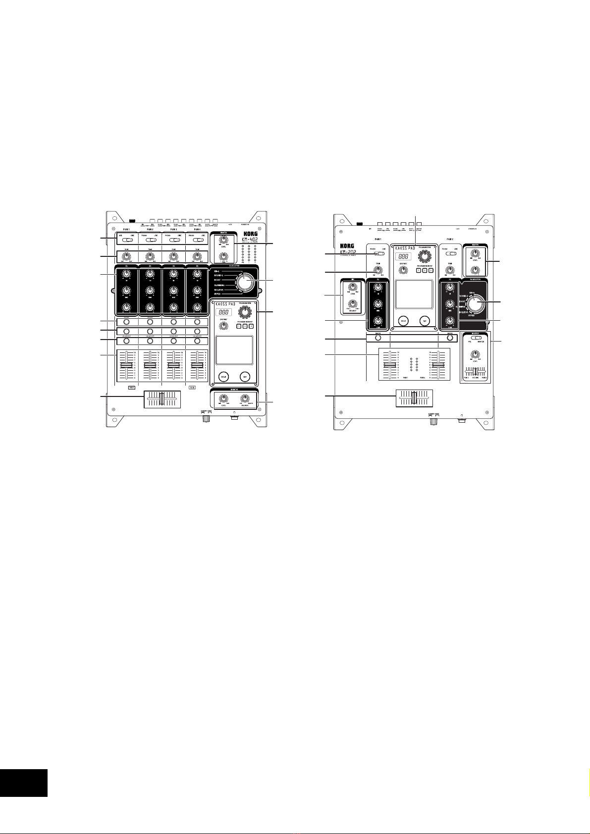
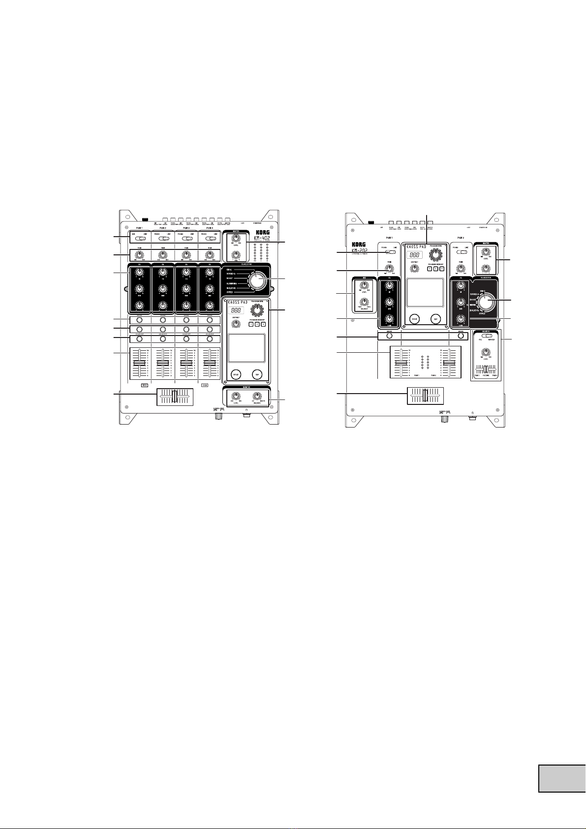
Parts and their functions
Top panel
1
2
4
5
6
7
8
3
14
11
10
9
1
2
13
44
5
8
3
14
12
10
9
1. INPUT SELECT switches
These select the input jacks that will be assigned to the corresponding mixer channel.
2. TRIM knobs
These adjust the level of the audio signal connected to the input jacks.
3. EQ SELECTOR knob
This selects the type of EQ. By switching the type, you can vary the tonal change produced by
adjusting the EQ knobs for the HI, MID, and LOW bands.
4. EQ knobs
The HI, MID, and LOW knobs control the tone by adjusting the corresponding frequency bands.
5. KAOSS buttons
These buttons can assign the mixer channel to the built-in KAOSS PAD effects. The effect is
applied to the mixer channel when the button is lit. When you press the button once again, the
button will go dark and the effect will be off.
6. (KM-402 only) CUE buttons
These buttons send the pre-fader sound of the mixer channel to the CUE bus. By setting the
MONITOR BALANCE knob toward CUE, you can monitor the sound of the CUE bus through
your headphones.
7. (KM-402 only) CH SELECT buttons
These assign the mixer channels to either channelA(green) or channel B (red) of the crossfader.
Each time you press a button, it will alternate between green ➝red ➝dark. If a mixer channel
is not assigned to either channel A or channel B (i.e., if its LED is dark), the sound of that mixer
channel will not pass through the crossfader.
5
8. Channel faders
These adjust the level of each mixer channel. Use them to adjust the volume balance between
channels.
9. Crossfader
You can use the crossfader to switch between two program sources, or to crossfade between
them for DJ-style performances.
(For the KM-402) This will crossfade between the audio signals assigned to channel A and
channel B by the CH SELECT buttons.
(For the KM-202) This will crossfade between PGM1 and PGM2.
10. MASTER LEVEL knob, MASTER PAN knob
These adjust the output level from the MASTER OUT jacks. Use the MASTER PAN knob to
adjust the L/R balance of the sound.
11. (KM-402 only) MONITOR BALANCE knob, MONITOR LEVEL knob
MONITOR BALANCE knob: If you turn this toward CUE, your headphones will monitor the
sound sent from each channel to the CUE bus. If you turn this toward MASTER, your head-
phones will monitor the sound sent from the MASTER OUT jacks.
MONITOR LEVEL knob: This adjusts the volume output from the headphone jack.
12. (KM-202 only) CUE/MASTER select switch, CUE MIX fader, MONITOR LEVEL knob
CUE/MASTER select switch: If this is in the CUE position, your headphones will monitor the
sound of the CUE bus. If this is in the MASTER position, your headphones will monitor the
same sound as the MASTER OUT jacks.
CUE MIX fader: This adjusts the volume balance of the CUE bus between PGM1 and PGM2.
MONITOR LEVEL knob: This adjusts the volume that is output from the headphone jack.
13. (KM-202 only) MIC LEVEL knob, MIC BALANCE knob
MIC LEVEL knob: This adjusts the input level from the MIC jack.
MIC BALANCE knob: This adjusts the balance of the MIC jack signal between PGM1 and
PGM2.
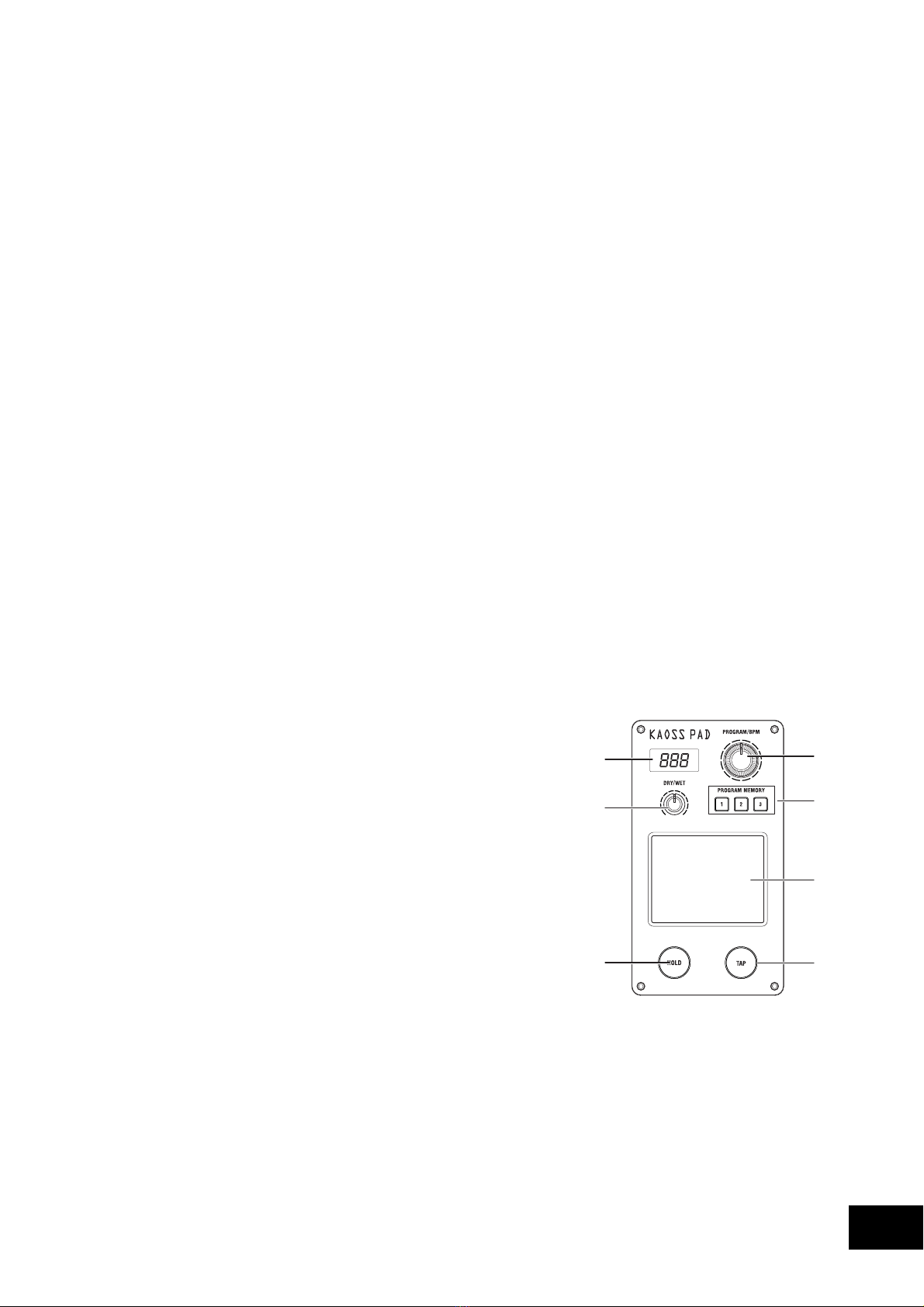
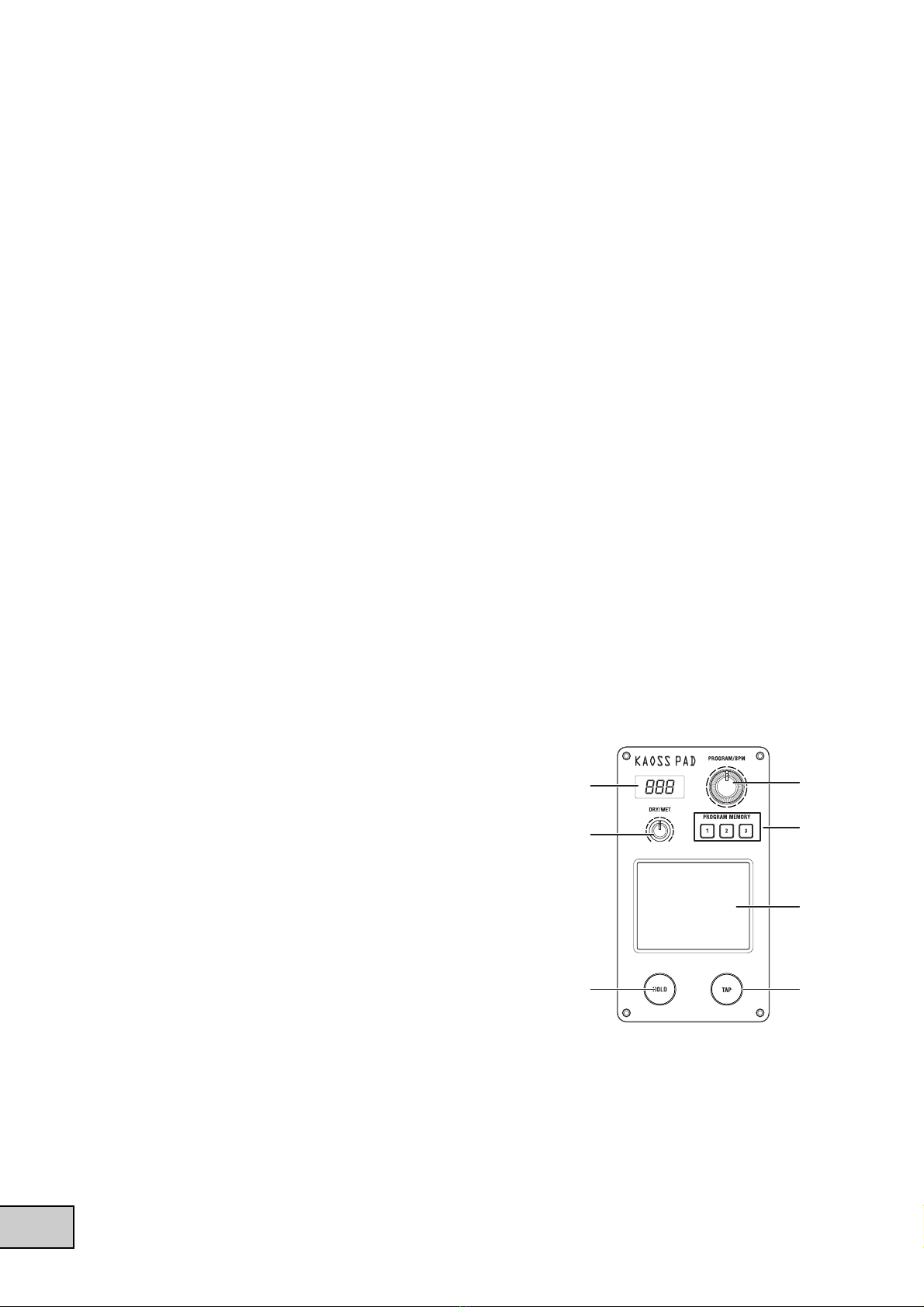
14. KAOSS PAD section
15. Display
This display shows the KAOSS PAD’s effect program
number, and the BPM.
16. DRY/WET knob
This adjusts the depth of the effect.
17. PROGRAM/BPM knob
Use this to select an effect program for the KAOSS PAD,
or to specify the BPM.
18. PROGRAM MEMORY buttons
You can store an effect program number in each of the
three Program Memory buttons, and then press one of
the buttons to instantly recall the stored program.
19. TOUCH PAD
This X/Y KAOSS pad can control two different parameters at once; one using the X-axis, and
one using the Y-axis—for inspired realtime control.
20. PAD HOLD button
The Hold feature memorizes the current position of your finger on the pad, so that you can
take your finger from the pad, and the effect will remain unchanged. Use this button to switch
the Hold feature on and off.
21. TAP button
You can specify the BPM value by pressing this button at the desired interval.
15
16 18
19
21
17
20

6
Front panel
12
1. X-FADER CURVE knob
This specifies the curve of the crossfader. Turn this knob to the right produces a “switch” effect,
turn the knob to the left produces a smoother transition. Please refer to the appendix for direc-
tions on how to change the crossfader settings.
2. Headphone jack
Rear panel
1234 6
7
58
12 34 6
7
58
1. Power switch
Turns the power on/off.
2. Power inlet
Connect the included power cable to this connector.
3. MASTER OUT jacks
These output the master bus’ audio signal. They are RCA-type output jacks.
4. BOOTH OUT jacks
These output the same audio signal as the MASTER OUT jacks. However, their volume is not
affected by the MASTER LEVEL knob. They are RCA-type output jacks.
5. INPUT (LINE) jacks
You can connect line level equipment to these jacks. They are RCA-type input jacks.
6. MIC jack
You can connect a mic to this jack. This is a 1/4" phone-type unbalanced input jack.
7. INPUT (PHONO) jacks
You can connect turntables to these jacks. They are RCA-type input jacks.
8. GND terminal
This is a grounding terminal for connecting your turntables. If you use the PHONO jacks, you
must connect the ground wire(s) of your turntable(s) to this GND terminal.

7
2. Getting ready
Before you connect your equipment, you must turn off the power switches and disconnect the power
cables from the outlet.
Connections
Use the jacks that are appropriate for the equipment you’re connecting.
KM-402
TURNTABLE
CD PLAYER
PA Mixer
KM-202
TURNTABLE
CD PLAYER
PA Mixer

8
Turning the power on
When powering-on this Mixer, you must observe the following procedure.
1. Connect the power cable.
Connect the included power cable to the power inlet.
2. Power-on the external devices connected to the mixer’s input jacks.
3. Turn down all of the Mixer’s channel faders and the MASTER VOLUME knob.
4. Turn on the power switch located on the rear panel of the mixer.
Power-on the equipment connected to the MASTER OUT jacks, such as your monitor amp.
Turning the power off
1. Turn down all of the Mixer’s channel faders and the MASTER VOLUME knob.
2. Turn off the power of your monitor amp or other equipment connected to the MASTER OUT
jacks.
3. Turn off the power switch located on the rear panel of the Mixer.

9
3. Using the mixer
Basic operation
Selecting the inputs
Use the top panel INPUT SELECT switch to select the desired inputs.
Adjusting the input levels
Use the TRIM knobs to adjust the input level of each mixer channel.
Adjust the TRIM knob so that the level indicator lights yellow with the channel fader at the maxi-
mum position, and when the level from the source is being input at its maximum level.
For the KM-202
Use the MIC LEVEL knob to adjust the input level of the mic connected to the MIC jack. Use
the MIC BALANCE knob to adjust the level balance that is sent to mixer channels PGM1 and
PGM2.
Mixing the sound
Use the channel faders to adjust the volume level of each mixer channel.
Using the crossfader
The audio mixed by the crossfader is output to the master bus or the FX bus.
Use the front panel X-FADER CURVE knob to adjust the curve (response) of the crossfader.
For the KM-402
Use the CH SELECT button to assign the corresponding
mixer channel to one of the two crossfader channels (A
or B).
Each time you press a CH SELECT button, it will alter-
nate between channel A (lit green) ➝channel B (lit red),
and➝unselected (dark).
For the KM-202
The crossfader will crossfade between PGM1 and PGM2.
Adjusting the master level
Use the MASTER LEVEL knob to adjust the overall volume level being sent from the MASTER OUT
jacks.
Monitoring
Connect your headphones to the headphone so that you can monitor the audio inputs or the sound
you’re mixing.
CUE
This is a function that lets you monitor (hear through headphones) the sound at a point before
the channel faders, separately from the sound that is output from the MASTER OUT jacks,
giving you a way to check the sound or “cue up” material while you’re performing. The sound
of the CUE bus can be monitored through headphones. This means that with the faders low-
ered, you can use headphones to check the audio input and EQ settings, and then when you’re
satisfied, raise the channel fader so that the desired sound will be sent from the master outputs.
lit green lit red

10
Monitoring via CUE
For the KM-402
1. Press the CUE button of the mixer channel you want to monitor.
2. Use the MONITOR BALANCE knob to adjust the volume balance between the master output
sound and the CUE bus sound.
Use the MONITOR LEVEL knob to adjust the overall volume.
For the KM-202
1. Use the CUE/MONITOR select switch to select CUE.
2. Use the CUE MIX fader to adjust the volume balance between PGM1 and PGM2. Use the
MONITOR LEVEL knob to adjust the overall volume.
Equalizer
Using the equalizer to adjust the sound
You can use the equalizer (EQ) to cut or boost the low, mid or high
frequency range as a creative sound-shaping tool.
1. Use the EQ SELECT knob to select the desired equalizer
type.
2. Control the EQ that you selected as the EQ type.
Use the HI/MID/LO knobs of each channel to modify the
tone as desired.
EQ type list
KM-Q
This is an equalizer that has been improved on the basis of opinions from numerous well-
known artists who are devoted users of the first-generation KAOSS mixer.
HI: -25dB–+15dB MID: -25dB–+15dB LO: -25dB–+15dB
ROUND-Q
This is an all-around EQ that is a good choice for all styles of music.
HI: -28dB–+12dB MID: -28dB–+12dB LO: -28dB–+12dB
BOOST
This is effective when used as a booster. The mid- and high-frequency ranges of change are
broad, letting you create powerful sounds.
HI: -20dB–+18dB MID: -12dB–+12dB LO: -20dB–+18dB
SLAMMING
In order to aggressively modify the mid-range sound, the HI is set to a frequency range that is
lower than normal and the MID to a range that is higher than normal. LO uses a special curve
that changes gently in the “+” direction and steeply in the “-” direction, letting you apply high
expressive equalization.
HI: -30dB–+6dB MID: -30dB–+6dB LO: -60dB–+6dB
ISOLATOR
This uses a trapezoidal curve, and applies equally to the sound within each frequency band. It
can be used as an isolator that completely cuts the sound, and is able to instantly cut the sound
of a specific part.
HI: -∞dB–+9dB MID: -∞dB–+9dB LO: -∞dB–+9dB
HYPED
This EQ has a gradual curve. It is useful for modifying the atmosphere of the entire song, as
well as for tonal adjustments.
HI: -∞dB–+9dB MID: -∞dB–+9dB LO: -∞dB–+9dB

11
4. Using the KAOSS PAD
Applying the KAOSS PAD effect to the channel
Press the KAOSS button of the mixer channel to make it light, the KAOSS PAD effect will be applied
to the sound from that mixer channel.
SOLO effect
If you press and hold the KAOSS button (for approximately two seconds), the KAOSS button you
pressed will blink, and the effect will be applied only to that Channel (KM-402) or PGM (KM-202).
Operating the touch pad
Control the effect by using your finger to rub or tap the touch pad.
Hold
If you press the HOLD button the HOLD indicator will light; in this state, you can take your finger off
the touch pad, and the sound of the effect immediately prior to that moment will be maintained.
Selecting an effect program
Turn the PROGRAM/VALUE knob to select an effect program 00–99. Use the DRY/WET knob to
adjust the depth of the effect.
Turning FX RELEASE on/off
1. While holding down the PROGRAM MEMORY 2 button, press the TAP key.
2. Use the PROGRAM/BPM knob to select “r.On” (FX RELEASE on) or “r.Of” (FX RELEASE off).
3. Once again, hold down the PROGRAM MEMORY 2 button and press the TAP key; you will re-
turn to the program selection state.
Alternatively, you will return to the program selection state if you don’t perform any setting
operation for three seconds.
What is FX RELEASE?
This produces a delay effect synchronized to the current BPM /tempo, and will begin the in-
stant you release your hand from the touch pad (i.e., the instant you turn off the effect), and
then decay gradually.
Using the PROGRAM MEMORY buttons
Each of the PROGRAM MEMORY buttons can memorize an effect program, the HOLD button’s on/
off status, and the position of the touch pad when HOLD is active.
By pressing a PROGRAM MEMORY button, you can instantly recall the memorized state.
To store the current settings to a PROGRAM MEMORY button
1. Before you continue, select the program that you want to memorize.
If you want to memorize the Hold status, press the HOLD button to turn the Hold function on.
The position at which you last touched the touch panel will be memorized.
2. While holding down the PROGRAM MEMORY button in which you want to memorize the
current state, press the HOLD button; the current state will be memorized in the PROGRAM
MEMORY button you’re pressing.

12
Setting the BPM
1. When you press the TAP button, the currently-specified BPM value is shown in the display.
2. If you press the TAP button several times in rhythm with the song tempo, the corresponding
BPM value will be detected, and the appropriate BPM value will be specified.
3. When the BPM value is displayed, you can turn the PROGRAM/BPM knob to modify the BPM
value.
4. If you hold down the TAP button, you will switch from the BPM setting back to the program
selection.
Alternatively, you will return to the program selection state if you don’t perform any setting
operation for five seconds.
Restoring the factory settings
To restore the factory settings, set the EQ SELECTOR knob to the “KM-Q” position, and then turn on
the power while holding down the TAP button and the PROGRAM MEMORY 1 button. All settings
of the KAOSS PAD will be restored to their factory-set state.

13
5. Appendix
Troubleshooting
Power does not turn on
•Is the power cable connected to a functioning electrical outlet?
•Is the rear panel power switch turned on?
No sound
•Is the KM-402/KM-202 powered-on? Are the connected devices powered-on?
•Are the channel faders or the MASTER LEVEL knob turned down?
•Is the volume level of the channel turned down?
•Is the TRIM knob raised to an appropriate level?
•After connecting your audio source to the input jacks, did you select it for the corresponding
mixer channel?
Set the INPUT SELECT switch appropriately for each mixer channel.
•Make sure that audio is being input.
Use the level meter to verify that audio is being received into each mixer channel.
Too much noise or distortion
•The sound will distort if the TRIM knob is set too high, and there will be more noise if the
TRIM knob is set too low.
To obtain the ideal setting, set the TRIM knob as high as possible without allowing the level
meter to light red at the maximum level. If the indicator lights red, the signal will clip, distort-
ing the sound.
•Could you be using the KAOSS PAD function?
Some of the KAOSS PAD effects intentionally add distortion or noise. Check whether noise or
distortion are still present even when you’re not using an effect.
•If the sound is distorting at the EQ, make the following adjustment.
Adjust the gain value of the EQ.
Adjusting the crossfader
You can adjust the left and right transition points of the crossfader.
The Left setting determines where on the crossfader’s travel Channel B (KM-402) or PGM 2 (KM-202)
will completely cease to sound. Likewise, the Right setting determines where on the crossfader's
travel CH A (KM-402) or PGM A (KM-202) will cease to sound.
Perform this adjustment if the sound does not transition correctly at the edge of the fader, or if you
want to shorten the fader stroke. Remember, the X-fader curve knob on the front panel will affect how
you perceive these settings.
1. Turn off the power.
2. Set the EQ SELECTOR knob to the “KM-Q” position, and then turn on the power while hold-
ing down the PROGRAM MEMORY 3 button and the TAP button.
The display will indicate “AdJ”, indicating that you’re in Crossfader Adjust mode.
3. Move the crossfader to the point at which you want it to begin taking effect.
When you move the fader to the left side, the display will indicate “L**”. When you move the
fader to the right side, the display will indicate “r**”. Each “**” can be adjusted in a range of
00–50.
Note: In some cases, the display may indicate “01” or “02” when the fader is all the way to one side.
4. At the point that you want to assign as the left and right edge, press the TAP button.
The decimal point for the “L.” or “r.” in the display will light, and the setting will be assigned
at that point. Repeat this step for the opposite side of the crossfader. (You can’t assign a point
that is shown as “--”.)

14
5. When you’ve specified the left and right points, hold down the HOLD button and press the
PROGRAM MEMORY 3 button.
The display will blink “SET”, and the settings will be stored. When the settings have been
stored, the display will indicate “End”.
6. To finish the setting, turn off the power, and then turn the power on again in the normal way.
Note: If you initialize the KAOSS PAD function to the factory-set state, the crossfader adjustment setting will
also be initialized.
Specifications
Power supply: AC Local Voltage
Power consumption: KM-402: 23W
KM-202: 20W (120V), 17W (220–230V)
Dimensions: 288mm (W) 384mm (D) 107mm (H) / 11.34" (W) 15.12" (D) 4.21" (H)
Weight: 5.0kg / 11.02lbs.
Frequency response: 20 Hz–20 kHz ±1.0 dB (Typ.)(LINE)
S/N: 90 dB @IHF-A (Typ.)(LINE)
INPUT (LINE)
Connectors: RCA jacks L/R
Input impedance: 10 kΩ
Nominal level: 0 dBu
PHONO
Connectors: RCA jacks
Input impedance: 40 kΩ
PHONO RIAA compliant
MIC INPUT
Connectors: 1/4" mono phone jack
Input impedance: 50 kΩ
Nominal level: -50 dBu
MASTER OUTPUT L/R
Connector: RCA jacks L/R
Nominal level: 0 dBu
Load impedance: greater than 10 kΩ
BOOTH OUTPUT L/R
Connector: RCA jacks L/R
Nominal level: 0 dBu
Load impedance: greater than 10 kΩ
PHONES OUTPUT
Connector: 1/4" stereo phone jack
Output impedance: 32 Ω
Maximum level: 80 mW + 80 mW @32 Ω
Included items
Power cable
Owner’s manual
* Appearance and specifications of this product are subject to change without notice.

15
INFORMATIONS IMPORTANTES DE SECURITE
•Lisez attentivement ces instructions.
•Veuillez conserver ces instructions.
•Observez tous les avertissements.
•Suivez toutes les consignes à la lettre.
•N’utilisez jamais cet appareil dans un endroit humide ni à proximité
d’eau.
•L’appareil alimenté par courant électrique ne peut pas être exposé
à des éclaboussures; évite en outre de placer des récipients
contenant des liquides, comme un vase (ou un verre de bière), sur
l’appareil.
•Nettoyez uniquement l’appareil avec un chiffon doux et sec.
•Ne bloquez jamais les orifices de ventilation de l’appareil et
installez-le toujours conformément aux instructions du fabricant.
•N’installez jamais l’appareil à proximité d’une source de chaleur,
telle que des radiateurs, poêles ou tout autre dispositif (y compris
des amplificateurs) générant de la chaleur.
•N’essayez jamais de contourner le dispositif de sécurité d’une prise
de type polarisée ou d’une prise de terre. Une prise dite polarisée
dispose de deux broches, dont l’une est plus large que l’autre. Une
prise de terre comporte trois broches, dont une de mise à la terre.
Cette broche plus large ou broche de mise à la terre vise à assurer
votre sécurité. Si la fiche du cordon d’alimentation ne correspond
pas au type de prise de courant de votre région, faites remplacer la
prise obsolète par un électricien qualifié (pour les Etats-Unis et le
Canada).
•Placez toujours le cordon d’alimentation de sorte qu’on ne risque
pas de marcher dessus ni de le pincer. Cette précaution vise tout
spécialement la fiche du cordon et sa sortie de l’appareil.
•Utilisez exclusivement les fixations/accessoires préconisés par le
fabricant.
•S’il y a risque d’orage ou que vous ne comptez pas utiliser
l’appareil pendant une période prolongée, débranchez-le du
secteur.
•La mise sur OFF de l’interrupteur d’alimentation n’isole pas
totalement ce produit de la ligne secteur; aussi, retirez la fiche de la
prise s’il doit rester inutilisé pendant une période prolongée.
•Installez ce produit près de la prise électrique murale et gardez un
accès facile à la prise électrique et au cordon d’alimentation.
•ATTENTION: Cet appareil doit absolument être connecté à une
prise électrique reliée à la terre.
•Confiez tout travail de réparation uniquement à un S.A.V. qualifié.
Faites appel au S.A.V. si l’appareil a subi tout endommagement,
comme par exemple si sa fiche secteur ou son cordon
d’alimentation sont endommagés, si de l’eau ou des objets ont
pénétré à l’intérieur de l’appareil, si celui-ci a été exposé à la pluie
ou à la moisissure, s’il est tombé ou présente tout signe de
dysfonctionnement.
•N’utilisez jamais d’allonge trop longue avec cet appareil et ne
l’alimentez jamais via les prises secteur équipant d’autres
dispositifs.
•N’installez jamais cet appareil dans un endroit confiné comme une
caisse de transport ou tout autre récipient similaire.
•Des niveaux d’écoute trop importants lors de l’utilisation d’un
casque ou d’écouteurs peuvent entraîner des pertes d’audition.
•Utilisez l’appareil uniquement avec le chariot, stand, trépied,
fixation ou table spécifiés par le fabricant ou fourni avec l’appareil.
Si vous avez placé l’appareil sur un chariot, soyez très prudent
quand vous déplacez le chariot, afin d’éviter une chute et des
blessures.
L’éclair dans le triangle est un symbole destiné à
attirer l’attention de l’utilisateur sur la présence de
parties non isolées et de “tension dangereuse” à
l’intérieur de l’appareil, qui posent des risques
d’électrocution pour l’utilisateur.
Le point d’exclamation dans un triangle est un
symbole destiné à attirer l’attention de l’utilisateur
sur des sections de ce manuel contenant des
informations importantes, liées à l’utilisation et à
l’entretien de ce produit.
Notice concernant l'élimination du produit
(UE seulement)
Si ce symbole “Poubelle barrée” est imprimé sur le produit
ou dans le manuel de l’utilisateur, vous devez vous
débarrasser du produit de la manière appropriée. Ne jetez
pas ce produit avec vos ordures ménagères. En vous
débarrassant correctement du produit, vous préviendrez les
dommages environnementaux et les risques sanitaires.La
méthode correcte d'élimination dépendra de votre lieu
d'habitation, aussi veuillez contacter les autorités locales concernées
pour les détails.
*Les noms de sociétés, noms de produits et noms de formats, etc.
dans ce manuel sont des marques de fabrique ou des mar-ques
déposées de leurs propriétaires respectifs.

16
Sommaire
1. Introduction .................................................. 17
Eléments et leurs fonctions........................................................... 17
2. Préparatifs.................................................... 20
Raccordements........................................................................... 20
Mise sous tension ....................................................................... 21
Mise hors tension ....................................................................... 21
3. Utilisation du mélangeur ............................... 22
Fonctionnement de base ............................................................. 22
Contrôle du son ......................................................................... 22
Égaliseur ................................................................................... 23
4. Utilisation du KAOSS PAD ............................. 24
Application de l’effet KAOSS PAD au canal ................................. 24
Fonctionnement du pavé tactile.................................................... 24
Sélection d’un programme d’effet ................................................ 24
Utilisation des touches PROGRAM MEMORY................................ 24
Réglage du BPM......................................................................... 25
Restauration des réglages d’usine ................................................ 25
5. Appendice .................................................... 26
Guide de dépannage ................................................................. 26
Réglage du crossfader ................................................................ 26
Spécifications............................................................................. 27
17
1. Introduction
Merci d’avoir fait l’acquisition du Korg KM-402/KM-202 DYNAMIC DJ MIXER. Afin de pouvoir
tirer le meilleur parti de toutes ses possibilités, nous vous conseillons de lire attentivement le pré-
sent manuel et d’utiliser le produit seulement de la manière indiquée.
Eléments et leurs fonctions
Panneau supérieur
1
2
4
5
6
7
8
3
14
11
10
9
1
2
13
44
5
8
3
14
12
10
9
1. Commutateurs INPUT SELECT
Utilisez ces commutateurs pour sélectionner les prises d’entrée qui seront assignées au canal
de mixeur correspondant.
2. Boutons TRIM
Utilisez ces boutons pour régler le niveau du signal audio reçu par les prises d’entrée.
3. Bouton EQ SELECTOR
Utilisez ce bouton pour sélectionner le type d’égaliseur. Commuter le type d’égaliseur permet
de modifier le caractère tonal quand vous réglez chacun des boutons EQ correspondant aux
plages HI, MID et LOW.
4. Boutons EQ
Les boutons HI, MID et LOW permettent de contrôler le caractère tonal en réglant les plages
de fréquences correspondantes.
5. Touches KAOSS
Utilisez ces touches pour assigner le canal de mixeur aux effets du KAOSS PAD intégré. L’ef-
fet est appliqué au canal de mixeur quand la touche est allumée. Si vous appuyez de nouveau
sur la touche, elle s’éteindra et l’effet sera désactivé.
6. (KM-402 seulement) Touches CUE
Utilisez ces touches pour envoyer le son pré-fader du canal de mixeur au bus CUE. En réglant
le bouton MONITOR BALANCE vers CUE, vous pouvez contrôler le son du bus CUE via un
casque.
7. (KM-402 seulement) Touches CH SELECT
Utilisez ces touches pour assigner les canaux de mixeur au canalA(vert) ou au canal B (rouge)
du crossfader. Chaque fois que vous appuyez sur une touche, elle changera alternativement
de vert ➝rouge ➝éteint. Si un canal de mixeur n’est assigné à aucun des canauxAou B (c’est-
à-dire, si la DELcorrespondante est éteinte), le son de ce canal de mixeur ne passera pas par le
crossfader.
18
15
16 18
19
21
17
20
8. Faders de canal
Utilisez ces faders pour régler le niveau de chaque canal de mixeur et la balance du volume
entre les canaux.
9. Crossfader
Utilisez le crossfader pour commuter entre deux sources de programme, ou pour effectuer
une transition de l’une à l’autre pour un effet de style DJ.
(Pour le KM-402) La transition se fera entre les signaux audio assignés au canal A et au canal B
avec les touches CH SELECT.
(Pour le KM-202) La transition se fera entre PGM1 et PGM2.
10. Bouton MASTER LEVEL, bouton MASTER PAN
Utilisez ces boutons pour régler le niveau de sortie des prises MASTER OUT. Utilisez le bou-
ton MASTER PAN pour régler la balance L/R (gauche/droite) du son.
11. (KM-402 seulement) Bouton MONITOR BALANCE, bouton MONITOR LEVEL
Bouton MONITOR BALANCE: Si vous tournez ce bouton vers CUE, votre casque repro-
duira le son provenant de chaque canal vers le bus CUE. Si vous le tournez vers MASTER,
votre casque reproduira le son provenant des prises MASTER OUT.
Bouton MONITOR LEVEL: Utilisez ce bouton pour régler le volume de sortie de la prise de
casque.
12. (KM-202 seulement) Sélecteur CUE/MASTER, fader CUE MIX, bouton MONITOR LEVEL
Sélecteur CUE/MASTER: Si ce sélecteur est dans la position CUE, votre casque reproduira le
son du bus CUE. S’il est dans la position MASTER, votre casque reproduira le même son que
celui des prises MASTER OUT.
Fader CUE MIX: Utilisez ce fader pour régler la balance du volume du bus CUE entre PGM1
et PGM2.
Bouton MONITOR LEVEL: Utilisez ce bouton pour régler le volume de la prise de casque.
13. (KM-202 seulement) Bouton MIC LEVEL, bouton MIC BALANCE
Bouton MIC LEVEL: Utilisez ce bouton pour régler le niveau d’entrée de la prise MIC.
Bouton MIC BALANCE: Utilisez ce bouton pour régler la balance du signal de la prise MIC
entre PGM1 et PGM2.
14. Section KAOSS PAD
15. Afficheur
L’afficheur indique le numéro de programme d’effet du
KAOSS PAD, et le BPM.
16. Bouton DRY/WET
Utilisez ce bouton pour régler l’intensité de l’effet.
17. Bouton PROGRAM/BPM
Utilisez ce bouton pour sélectionner un programme d’ef-
fet pour le KAOSS PAD, ou pour spécifier le BPM.
18. Touches PROGRAM MEMORY
Vous pouvez stocker un numéro de programme d’effet
sous chacune des trois touches Program Memory, puis
appuyer sur une des touches pour rappeler instantané-
ment le programme stocké.
19. TOUCH PAD
Ce pavé tactile X/Y KAOSS peut contrôler simultanément
deux paramètres différents; l’un en utilisant l’axe X et l’autre en utilisant l’axe Y pour un
contrôle artistique en temps réel.
20. Touche PAD HOLD
La fonction Hold mémorise la position actuelle de votre doigt sur le pavé tactile. Quand vous
retirez votre doigt de la surface du pavé tactile, l’effet reste dans l’état dans lequel il était
quand vous aviez touché précédemment le pavé tactile. Utilisez cette touche pour activer et
désactiver la fonction Hold.
21. Touche TAP
Vous pouvez spécifier la valeur de BPM en appuyant sur cette touche à l’intervalle souhaité.

19
Panneau avant
12
1. Bouton X-FADER CURVE
Utilisez ce bouton pour spécifier la forme de courbe du crossfader. Tournez ce bouton vers la
droite pour produire un effet de “déclenchement”, tournez-le vers la gauche pour produire
une transition douce. Veuillez vous reporter à l’appendice pour les directives sur la façon de
changer les réglages de crossfader.
2. Prise de casqu
Panneau arrière
1234 6
7
58
12 34 6
7
58
1. Commutateur de mise sous/hors tension
Utilisez ce commutateur pour mettre l’appareil sous/hors tension.
2. Prise d’alimentation
Branchez sur cette prise le cordon d’alimentation fourni.
3. Prises MASTER OUT
Ces prises fournissent le signal audio du bus maître. Ce sont des prises de sortie de type RCA.
4. Prises BOOTH OUT
Ces prises fournissent le même signal audio que les prises MASTER OUT. Néanmoins, leur
volume n’est pas affecté par le bouton MASTER LEVEL. Ce sont des prises de sortie de type
RCA.
5. Prises INPUT (LINE)
Vous pouvez raccorder à ces prises du matériel de niveau ligne. Ce sont des prises d’entrée de
type RCA.
6. Prise MIC
Vous pouvez raccorder à cette prise un micro. C’est un jack TRS 6,35.
7. Prises INPUT (PHONO)
Vous pouvez raccorder à ces prises des platines tourne-disques. Ce sont des prises d’entrée de
type RCA.
8. Borne GND
Il s’agit d’une borne de mise à la terre pour les platines tourne-disques. Si vous utilisez les
prises PHONO, vous devez raccorder le(s) fil(s) de terre de votre/vos platine(s) tourne-dis-
ques à cette borne GND.

20
2. Préparatifs
Avant de raccorder votre équipement, vous devez mettre les appareils hors tension et débrancher
les cordons d’alimentation du secteur.
Raccordements
Utilisez les prises appropriées pour les appareils que vous raccordez.
KM-402
TURNTABLE
CD PLAYER
PA Mixer
KM-202
TURNTABLE
CD PLAYER
PA Mixer
This manual suits for next models
1
Table of contents
Languages:
Other Korg Music Mixer manuals


